EP0264352A1 - A percolator holding pan for espresso coffee making machine - Google Patents
A percolator holding pan for espresso coffee making machine Download PDFInfo
- Publication number
- EP0264352A1 EP0264352A1 EP87830355A EP87830355A EP0264352A1 EP 0264352 A1 EP0264352 A1 EP 0264352A1 EP 87830355 A EP87830355 A EP 87830355A EP 87830355 A EP87830355 A EP 87830355A EP 0264352 A1 EP0264352 A1 EP 0264352A1
- Authority
- EP
- European Patent Office
- Prior art keywords
- percolator
- holding pan
- membrane
- pan according
- cupped
- Prior art date
- Legal status (The legal status is an assumption and is not a legal conclusion. Google has not performed a legal analysis and makes no representation as to the accuracy of the status listed.)
- Granted
Links
Images

Classifications
-
- A—HUMAN NECESSITIES
- A47—FURNITURE; DOMESTIC ARTICLES OR APPLIANCES; COFFEE MILLS; SPICE MILLS; SUCTION CLEANERS IN GENERAL
- A47J—KITCHEN EQUIPMENT; COFFEE MILLS; SPICE MILLS; APPARATUS FOR MAKING BEVERAGES
- A47J31/00—Apparatus for making beverages
- A47J31/06—Filters or strainers for coffee or tea makers ; Holders therefor
- A47J31/0605—Filters or strainers for coffee or tea makers ; Holders therefor with a valve at the filter-outlet; Anti-drip devices
Definitions
- This invention relates to a percolator holding pan for "espresso" coffee making machines, being of a type which comprises a body adapted for fitting to a delivery assembly of an "espresso" coffee making machine; a cavity formed in said body and having a bottom; a cupped percolator intended for holding the coffee powder and housed within said cavity; at least one "espresso” coffee dispensing spout; and a liquid flow path extending through said body between the cupped percolator and said at least one spout, and including a compartment provided at a location between said cupped percolator and said bottom.
- the delivery time -- i.e. the time required to complete the percolation process -- and, hence, the flow rate, should be set at optimum values ensuring satisfactory results from the organoleptic standpoint.
- Such values are directly dependent on the pressure of the water upstream of the coffee powder charge and the ground coffee size, since the coffee powder charge is bound to form a filtering element effecting upstream a pressure value which obviously reflect on the liquid coffee delivery rate.
- the flow rate value for the same conditions of water pressure upstream of the filtering element formed by the coffee powder, is also tied to many other factors, such as the coffee variety being used, moisture content, ageing of the powder, pressing the powder within the cupped percolator, and a number of contingent weather factors which can change upon occasion and usually make adjustment rather problematical.
- the coffee delivery time, and therefore the rate at which it will be dispensed downstream of the percolator, are substantial to the obtainment of a rich "espresso" coffee with a fine flavor.
- too low a flow rate is apt to yield an "espresso” coffee with a thin head or "cream", dark colored and tasting bitter, commonly referred to as “burned” coffee
- an excessively high flow rate yields an "espresso” coffee having a weakly flavored pale colored head which make the "espresso” coffee more akin to an ordinary coffee infusion.
- the problem underlying this invention is to provide a percolator holding pan of the type specified above, which has such constructional and operational features as to overcome the aforementioned shortcoming.
- a percolator holding pan as indicated being characterized in that it comprises pressure control means placed in said path for controlling the pressure downstream of the cupped percolator.
- Said pressure control means advantageously comprise a restrictor effective to produce a pilot backpressure, and a shut-off valve located between the cupped percolator and the restrictor and being piloted by said backpressure.
- a percolator holding pan according to the invention comprises a body 1 which is formed with a handle 2 and bayonet coupling elements 3 for fitting to a delivery assembly of an "espresso" coffee maker.
- the body 1 defines on its interior a cavity 4 adapted to accommodate a cupped percolator 5 to be loaded with a charge of coffee powder and which is acted upon by a ring seal 8 provided in the side wall of the cavity 4.
- An underpan 10 having dispensing spouts 11 is connected to the bottom of the body 1.
- the gist of the invention resides in that means of controlling the "espresso" coffee delivery pressure are provided at a port 20 which is formed through the bottom of the cavity 4 and puts the cavity in communication with the dispensing spouts 11.
- control means consist of a needle 21 formed at the tip with a conical termination 22 acting on the port 20 so as to control its working cross-sectional area.
- the needle 21 has, at a middle portion thereof, a ballasting body or weight 25 which is contained inside a compensation chamber, generally indicated at 26, which is defined between the bottom outside of the cavity and a deformable membrane 30 defining an outlet port 31, in a middle portion thereof, which also functions as a lower guide member for the needle 21.
- the deformable membrane is urged upwards by a spring 32 arranged to act between the cited underpan 10 and a central bulge 34 defined by the membrane and which forms, in its corresponding inward portion, the actual area accommodating the weight 25.
- the compensation chamber should have extremely small volume dimensions in order to avoid unnecessary stagnation sites.
- slender ridges 36 are provided to hold the membrane off, thus affording small dimensions for the chamber.
- such a minimized volume compensation chamber should have a pitched configuration toward the outlet hole in order to prevent formation of residues and stagnation sites for obvious sanitary considerations.
- the spacers 35 will function as a stop for the weight 25, preventing it from blocking the inlet port 20 to the compensation chamber 26.
- ports 20 and outlet ports 31 should be calibrated to control the flow with the utmost accuracy in order to provide the required delivery pressure on the occurrence of an eccessively high flow.
- the optimum diameter dimension of the port is within the range of 1.5 mm to 2.5 mm, with an 0.8-1.5 mm needle; the output port will then have a diameter equal to or smaller than that of the port 20.
- the needle 10 will leave the port 20 uncovered while throttling down the calibrated outlet port 31 defined in the membrane 30 with its calibrated stem.
- the presence of the needle inside the two calibrated holes forming the port 20 and outlet port 31 affords self-cleaning of the two holes, in a simple manner upon loading and shaking out the coffee grounds, thereby ensuring perfect dimensional stability of the holes, and hence, correct performance over time.
- the weight 25, allowed to rest on the membrane and rigid with the needle, will move down in consequence such that its conical tip 22 tends to cover the inlet port and throttle the flow further down, thus reducing the flow rate until a desired flow rate is achieved.
- the percolator holding pan affords control over the flow pressure in a virtually automatic manner because of the pressure established downstream of the cupped percolator on closing the port in the event that the flow of coffee proves to be too fast.
- a safety valve may be provided to relieve the pressure in the event that, for a reason whatever, excessively high internal pressures are created.
- drain holes 40 are provided in the bottom of the underpan 10 .
- a percolator holding pan 51 comprises an aluminum body 52 having a handle 53 and bayonet coupling elements 54 for fitting to a delivery assembly of an "espresso" coffee maker.
- a cavity 55 having a bottom 56 In the body 1, there is formed a cavity 55 having a bottom 56.
- the cavity 55 accommodates a cupped percolator 57 for the coffee powder, which defines in said cavity 55 a compartment 58 formed between the cupped percolator and the bottom 55.
- Two “espresso" coffee dispensing spouts are provided on the body 52 at the bottom 56, thereby forming through said body 52 a liquid path, designated 60, which extends between the cupped percolator 57 and the spouts 59 and including said compartment 58.
- the percolator holding pan 51 of this invention includes pressure control means 61 located in the path 60 for controlling the pressure downstream of the cupped percolator 57.
- These pressure control means 61 comprise a restrictor 62, effective to produce a pilot backpressure, and a shut-off valve 63, interposed to the cupped percolator 57 and the restrictor 62 and being piloted by said backpressure.
- the restrictor 62 has a calibrated port 64 formed through an elastically deformable membrane 65 lying in the compartment 58. More specifically, the calibrated port 64 is formed in a nozzle 66 of a non-sticking material removably push-fitted in the membrane 65 at a bulge 67 thereof.
- the periphery of the membrane 65 is configured as a toric ring 87 whereby it is held in the body 52.
- the body 52 is formed in two juxtaposed parts 88 and 89, held together by screw fasteners and defining a seat 90 for said toric ring.
- the membrane will deform relatively to the toric ring, generating neither friction nor jerks.
- the shut-off valve 63 includes a shutter seat 68, formed in a partition 69 provided in said compartment 58 between the cupped percolator 57 and the membrane 56, and a shutter 70, which is arranged to contact the membrane 65 and is movable toward and away from said shutter seat 68 by the action of said membrane.
- a chamber 71 Formed between the partition 69 and the membrane 65 is a chamber 71 wherein said backpressure prevails and whose volume will change as the backpressure varies according to the extent by which the membrane is deformed.
- a spring 72 is mounted betw een the membrane 65 and the bottom 56 to constantly bias the membrane 65 toward the partition 69.
- Indicated at 73 are raised splines formed on the partition 69, which provide spacers effective to prevent the membrane 65 from resting across the entire surface of the partition 69 with the volume of the chamber 71 at a minimum, thereby preventing the membrane from sticking to the partition.
- the shutter seat 68 would be formed preferably within an insert 74 of a non-sticking and non-rusting material, force fitted into said partition.
- the shutter 70 comprises a needle 75 received through the shutter seat 68 and having a frustoconical tip 76 mating with the shutter seat 68 to control the shutter passage cross-section.
- the shutter 70 further comprises an enlargement 77, formed along the needle 75, which is seated in a seat 78 formed in the bulge 77.
- the enlargement 77 provides weight to hold the shutter 68 in contact with the membrane 65.
- This contact is effected by engagement of the enlargement 77 with ridges 79 formed on the membrane.
- a conduit 80 formed in the body 52 and being open to the outside, in which a safety valve 81 is mounted.
- the percolator holding pan 51 includes a plug 82, push fitted removably at the bottom 56, the spouts 59 being formed on said plug 82.
- the plug 82 has a tubular portion 83 jutting into the compartment 58.
- the tubular portion 83 forms inwardly a collecting well 84, upstream of the spouts, and defines outwardly an annular groove 85 for receiving and centering one end of the spring 72, the other spring end being fitted over the bulge 68.
- Said annular groove 85 is provided with drain holes 86 to prevent stagnation within the groove itself.
- the diameter of the plug 82 should be selected for convenient access to the nozzle 66, removal and re-assembling thereof.
- the spouts 59 have their ends cut obliquely, to a so-called flute mouthpiece configuration, with diverging tips to hold the flows of "espresso" coffee issuing from the spouts well apart.
- the main advantage of the percolator holding pan according to the invention resides in that it adjusts the flow rate of the delivered stream in an automatic manner, irrespective of the nature and state of the coffee powder being used, thus contributing toward optimum utilization of the coffee powder.
- the use of the percolator holding pan according to the invention yields "espresso" coffee of excellent quality, without requiring application of any special skill or reiterated attempts at perfecting the coffee powder pressing operation as dictated each time by the coffee powder actually employed.
- the percolator holding pan of this invention is also advantageous from the sanitary standpoint. In fact, all the "espresso" coffee will readily flow out of the percolator holding pan at each delivery. In all cases, it has proved easy and quick to clean out.
- the holding pan of this invention is also advantageous from the standpoint of safety in use.
- An additional advantage of the inventive percolator holding pan is that its construction is simple and reliable, thereby affording flawless operation either following a number of successive deliveries or prolonged off cycles.
Abstract
Description
- This invention relates to a percolator holding pan for "espresso" coffee making machines, being of a type which comprises a body adapted for fitting to a delivery assembly of an "espresso" coffee making machine; a cavity formed in said body and having a bottom; a cupped percolator intended for holding the coffee powder and housed within said cavity; at least one "espresso" coffee dispensing spout; and a liquid flow path extending through said body between the cupped percolator and said at least one spout, and including a compartment provided at a location between said cupped percolator and said bottom.
- As is known, to prepare a good, rich "espresso" coffee, the delivery time -- i.e. the time required to complete the percolation process -- and, hence, the flow rate, should be set at optimum values ensuring satisfactory results from the organoleptic standpoint.
- Such values are directly dependent on the pressure of the water upstream of the coffee powder charge and the ground coffee size, since the coffee powder charge is bound to form a filtering element effecting upstream a pressure value which obviously reflect on the liquid coffee delivery rate.
- It is a recognized fact that coarse grinding results in increased flow rate, and consequently shorter delivery time, whereas fine grinding leads to decreased flow rate, with longer delivery time as a consequence.
- Note should be made that the flow rate value, for the same conditions of water pressure upstream of the filtering element formed by the coffee powder, is also tied to many other factors, such as the coffee variety being used, moisture content, ageing of the powder, pressing the powder within the cupped percolator, and a number of contingent weather factors which can change upon occasion and usually make adjustment rather problematical.
- It should be further noted that the coffee delivery time, and therefore the rate at which it will be dispensed downstream of the percolator, are substantial to the obtainment of a rich "espresso" coffee with a fine flavor. In fact, too low a flow rate is apt to yield an "espresso" coffee with a thin head or "cream", dark colored and tasting bitter, commonly referred to as "burned" coffee, whereas an excessively high flow rate yields an "espresso" coffee having a weakly flavored pale colored head which make the "espresso" coffee more akin to an ordinary coffee infusion.
- The aforementioned settings have been quite difficult to make heretofore, and have largely relied on the operator's skill, the operator being each time forced to adjust the coffee grinding, pressing, and the like settings until an optimum result can be obtained.
- The problem underlying this invention is to provide a percolator holding pan of the type specified above, which has such constructional and operational features as to overcome the aforementioned shortcoming.
- This problem is solved by a percolator holding pan as indicated being characterized in that it comprises pressure control means placed in said path for controlling the pressure downstream of the cupped percolator.
- Said pressure control means advantageously comprise a restrictor effective to produce a pilot backpressure, and a shut-off valve located between the cupped percolator and the restrictor and being piloted by said backpressure.
- Further features and the advantages of the percolator holding pan according to this invention will become apparent from the following detailed description of a preferred embodiment thereof, to be taken by way of illustration and not of limitation in conjunction with the accompanying drawings, where:
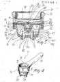
- Figure 1 is a perspective view of a percolator holding pan according to the invention;
- Figure 2 is a sectional view of the percolator holding pan shown in Figure 1, taken along the line I-I;
- Figure 3 is a detail view of the percolator holding pan shown in Figure 1, taken in the direction of the arrow III;
- Figure 4 is a perspective view of a modified embodiment of the percolator holding pan according to the invention; and
- Figure 5 is a sectional view of the percolator holding pan shown in Figure 4, taken along the line VI-VI.
- With reference to the drawing figures, a percolator holding pan according to the invention comprises a body 1 which is formed with a handle 2 and
bayonet coupling elements 3 for fitting to a delivery assembly of an "espresso" coffee maker. - The body 1 defines on its interior a
cavity 4 adapted to accommodate a cuppedpercolator 5 to be loaded with a charge of coffee powder and which is acted upon by aring seal 8 provided in the side wall of thecavity 4. - An
underpan 10 having dispensingspouts 11 is connected to the bottom of the body 1. - The gist of the invention resides in that means of controlling the "espresso" coffee delivery pressure are provided at a
port 20 which is formed through the bottom of thecavity 4 and puts the cavity in communication with thedispensing spouts 11. - These control means consist of a
needle 21 formed at the tip with aconical termination 22 acting on theport 20 so as to control its working cross-sectional area. Theneedle 21 has, at a middle portion thereof, a ballasting body orweight 25 which is contained inside a compensation chamber, generally indicated at 26, which is defined between the bottom outside of the cavity and adeformable membrane 30 defining anoutlet port 31, in a middle portion thereof, which also functions as a lower guide member for theneedle 21. - The deformable membrane is urged upwards by a
spring 32 arranged to act between the citedunderpan 10 and acentral bulge 34 defined by the membrane and which forms, in its corresponding inward portion, the actual area accommodating theweight 25. - At the inward portion of the cited
bulge 34, there are providedspacers 35 which serve as rest members for the weight effective to prevent it from fully blocking theoutlet port 31. The compensation chamber should have extremely small volume dimensions in order to avoid unnecessary stagnation sites. To prevent thedeformable membrane 30 from sticking to the outside bottom of the cavity defined by the body 1, under the thrust of the spring,slender ridges 36 are provided to hold the membrane off, thus affording small dimensions for the chamber. Further, such a minimized volume compensation chamber should have a pitched configuration toward the outlet hole in order to prevent formation of residues and stagnation sites for obvious sanitary considerations. - In addition, the
spacers 35 will function as a stop for theweight 25, preventing it from blocking theinlet port 20 to thecompensation chamber 26. - It stands to reason that the
ports 20 andoutlet ports 31 should be calibrated to control the flow with the utmost accuracy in order to provide the required delivery pressure on the occurrence of an eccessively high flow. - It has been found in the course of actual tests that, where a pump with a 10-15 atm capacity is used for the coffee maker, the optimum diameter dimension of the port is within the range of 1.5 mm to 2.5 mm, with an 0.8-1.5 mm needle; the output port will then have a diameter equal to or smaller than that of the
port 20. - Particularly in the inoperative condition, the
needle 10 will leave theport 20 uncovered while throttling down the calibratedoutlet port 31 defined in themembrane 30 with its calibrated stem. - The presence of the needle inside the two calibrated holes forming the
port 20 andoutlet port 31 affords self-cleaning of the two holes, in a simple manner upon loading and shaking out the coffee grounds, thereby ensuring perfect dimensional stability of the holes, and hence, correct performance over time. - To make an "espresso" coffee, water is admitted under pressure through the filter formed by the coffee powder, thereby a flow path of coffee percolate is formed leading into the compensation chamber through the
hole 20. Should the flow prove excessive, i.e. the coffee be delivered within too short a time, theoutlet hole 31, which is throttled down by the needle at the bottom of the compensation chamber, practically creates then a dinamic barrier effective to trigger a backpressure within said chamber which causes the membrane to become deformed by pushing it downwards against the bias of thespring 32. - The
weight 25, allowed to rest on the membrane and rigid with the needle, will move down in consequence such that itsconical tip 22 tends to cover the inlet port and throttle the flow further down, thus reducing the flow rate until a desired flow rate is achieved. - Thus, the percolator holding pan affords control over the flow pressure in a virtually automatic manner because of the pressure established downstream of the cupped percolator on closing the port in the event that the flow of coffee proves to be too fast.
- It should be added to the foregoing that a safety valve may be provided to relieve the pressure in the event that, for a reason whatever, excessively high internal pressures are created.
- Furthermore, provided in the bottom of the
underpan 10 aredrain holes 40 effective to prevent the formation of stagnant pockets of any kind. - With reference to Figures 4 and 5, a
percolator holding pan 51 according to the invention comprises analuminum body 52 having ahandle 53 andbayonet coupling elements 54 for fitting to a delivery assembly of an "espresso" coffee maker. - In the body 1, there is formed a cavity 55 having a
bottom 56. - The cavity 55 accommodates a cupped
percolator 57 for the coffee powder, which defines in said cavity 55 acompartment 58 formed between the cupped percolator and the bottom 55. - Two "espresso" coffee dispensing spouts, both indicated at 59, are provided on the
body 52 at thebottom 56, thereby forming through said body 52 a liquid path, designated 60, which extends between thecupped percolator 57 and thespouts 59 and including saidcompartment 58. - The
percolator holding pan 51 of this invention includes pressure control means 61 located in thepath 60 for controlling the pressure downstream of the cuppedpercolator 57. - These pressure control means 61 comprise a restrictor 62, effective to produce a pilot backpressure, and a shut-off
valve 63, interposed to the cuppedpercolator 57 and the restrictor 62 and being piloted by said backpressure. - The restrictor 62 has a
calibrated port 64 formed through an elasticallydeformable membrane 65 lying in thecompartment 58. More specifically, thecalibrated port 64 is formed in anozzle 66 of a non-sticking material removably push-fitted in themembrane 65 at a bulge 67 thereof. - The periphery of the
membrane 65 is configured as atoric ring 87 whereby it is held in thebody 52. To this end, thebody 52 is formed in two juxtaposedparts seat 90 for said toric ring. The membrane will deform relatively to the toric ring, generating neither friction nor jerks. - The shut-off
valve 63 includes ashutter seat 68, formed in a partition 69 provided in saidcompartment 58 between thecupped percolator 57 and themembrane 56, and ashutter 70, which is arranged to contact themembrane 65 and is movable toward and away from saidshutter seat 68 by the action of said membrane. - Formed between the partition 69 and the
membrane 65 is achamber 71 wherein said backpressure prevails and whose volume will change as the backpressure varies according to the extent by which the membrane is deformed. - It should be noted that a
spring 72 is mounted betw een themembrane 65 and thebottom 56 to constantly bias themembrane 65 toward the partition 69. - Indicated at 73 are raised splines formed on the partition 69, which provide spacers effective to prevent the
membrane 65 from resting across the entire surface of the partition 69 with the volume of thechamber 71 at a minimum, thereby preventing the membrane from sticking to the partition. - In particular, the
shutter seat 68 would be formed preferably within aninsert 74 of a non-sticking and non-rusting material, force fitted into said partition. - The
shutter 70 comprises aneedle 75 received through theshutter seat 68 and having afrustoconical tip 76 mating with theshutter seat 68 to control the shutter passage cross-section. - The
shutter 70 further comprises an enlargement 77, formed along theneedle 75, which is seated in aseat 78 formed in the bulge 77. The enlargement 77 provides weight to hold theshutter 68 in contact with themembrane 65. - This contact is effected by engagement of the enlargement 77 with
ridges 79 formed on the membrane. - From the
path 60, at a location directly downstream of the cuppedpercolator 57 and upstream of the pressure control means 61, there branches off a conduit 80, formed in thebody 52 and being open to the outside, in which a safety valve 81 is mounted. - The
percolator holding pan 51 includes aplug 82, push fitted removably at thebottom 56, thespouts 59 being formed on saidplug 82. - The
plug 82 has atubular portion 83 jutting into thecompartment 58. Thetubular portion 83 forms inwardly a collecting well 84, upstream of the spouts, and defines outwardly anannular groove 85 for receiving and centering one end of thespring 72, the other spring end being fitted over thebulge 68. - Said
annular groove 85 is provided withdrain holes 86 to prevent stagnation within the groove itself. - The diameter of the
plug 82 should be selected for convenient access to thenozzle 66, removal and re-assembling thereof. - The
spouts 59 have their ends cut obliquely, to a so-called flute mouthpiece configuration, with diverging tips to hold the flows of "espresso" coffee issuing from the spouts well apart. - During the delivery of the "espresso" coffee, and for any grinding grade of the coffee powder or pressing thereof or the like, it has been found that delivery proceeds at nearly constant flow rate. This is owed to higher or lower flow rates than optimum immediately generating, in passing the restrictor 62, higher or lower backpressures, respectively, in the
chamber 71, and accordingly, a larger or smaller displacement of themembrane 65 away from the partition. This results in the shutter being brought more or less close to the shutter seat. The net result is an increase or decrease of the pressure downstream of the cupped percolator which will prevail until the flow rate settles at the desired optimum value. - The main advantage of the percolator holding pan according to the invention resides in that it adjusts the flow rate of the delivered stream in an automatic manner, irrespective of the nature and state of the coffee powder being used, thus contributing toward optimum utilization of the coffee powder.
- In other words, the use of the percolator holding pan according to the invention yields "espresso" coffee of excellent quality, without requiring application of any special skill or reiterated attempts at perfecting the coffee powder pressing operation as dictated each time by the coffee powder actually employed.
- The percolator holding pan of this invention is also advantageous from the sanitary standpoint. In fact, all the "espresso" coffee will readily flow out of the percolator holding pan at each delivery. In all cases, it has proved easy and quick to clean out.
- The holding pan of this invention is also advantageous from the standpoint of safety in use.
- An additional advantage of the inventive percolator holding pan is that its construction is simple and reliable, thereby affording flawless operation either following a number of successive deliveries or prolonged off cycles.
- Lastly, it lends itself for use in lieu of a conventional one, to retrofit any "espresso" coffee maker whether of a professional or household type.
- Understandably, several modifications and alterations may be applied to the percolator holding pans disclosed hereinabove, to meet specific contingent requirements, without departing from the protection scope of the invention as set forth in the appended claims.
Claims (18)
Priority Applications (1)
| Application Number | Priority Date | Filing Date | Title |
|---|---|---|---|
| AT87830355T ATE88331T1 (en) | 1986-10-08 | 1987-10-07 | BREWING HEAD FOR ESPRESSO COFFEE MACHINES. |
Applications Claiming Priority (2)
| Application Number | Priority Date | Filing Date | Title |
|---|---|---|---|
| IT21942/86A IT1197368B (en) | 1986-10-08 | 1986-10-08 | FILTER HOLDER CUP WITH CAPACITY ADJUSTMENT MEASURES FOR COFFEE MACHINES |
| IT2194286 | 1986-10-08 |
Publications (2)
| Publication Number | Publication Date |
|---|---|
| EP0264352A1 true EP0264352A1 (en) | 1988-04-20 |
| EP0264352B1 EP0264352B1 (en) | 1993-04-21 |
Family
ID=11189160
Family Applications (1)
| Application Number | Title | Priority Date | Filing Date |
|---|---|---|---|
| EP87830355A Expired - Lifetime EP0264352B1 (en) | 1986-10-08 | 1987-10-07 | A percolator holding pan for espresso coffee making machine |
Country Status (7)
| Country | Link |
|---|---|
| US (1) | US4882982A (en) |
| EP (1) | EP0264352B1 (en) |
| AT (1) | ATE88331T1 (en) |
| CA (1) | CA1280902C (en) |
| DE (1) | DE3785539T2 (en) |
| ES (1) | ES2041272T3 (en) |
| IT (1) | IT1197368B (en) |
Cited By (18)
| Publication number | Priority date | Publication date | Assignee | Title |
|---|---|---|---|---|
| FR2636828A1 (en) * | 1988-09-28 | 1990-03-30 | Soler Saez Daniel | Filter holder intended for machines for preparing infusions |
| FR2655529A1 (en) * | 1989-12-13 | 1991-06-14 | Seb Sa | Electrical appliance for making drinks by rapid extraction under pressure |
| EP0449792A1 (en) * | 1990-03-28 | 1991-10-02 | ARIETE S.r.l. | Improved filter holder for a percolator |
| EP0459323A2 (en) * | 1990-05-30 | 1991-12-04 | Moulinex | Percolator holder for espresso coffee making machines |
| EP0523278A1 (en) * | 1991-07-19 | 1993-01-20 | Eugster/Frismag AG | Espresso coffee machine |
| EP0622039A1 (en) * | 1993-04-27 | 1994-11-02 | ESSEGIELLE S.r.l | Percolator cup for espresso coffee machines |
| EP0682902A1 (en) * | 1994-03-11 | 1995-11-22 | Briel - Industria De Electrodomesticos, S.A. | Back-pressure filter, to prepare cream coffee |
| WO1997026815A1 (en) * | 1996-01-25 | 1997-07-31 | Robert Krups Gmbh & Co. Kg | Filter-holder for coffee machine of the espresso type |
| WO2000007488A1 (en) * | 1998-08-06 | 2000-02-17 | Oficina De Investigacion Agrupada, S.A. | Filter for espresso coffee machine with a cream producing device |
| EP1016364A3 (en) * | 1998-12-18 | 2000-11-02 | Antica Torref. del Borgo Bardassano snc di Boido Aldo e C. | Device and process for the formation of cream, usable on machines for the preparation of infusions, in particular coffee |
| EP1133944A2 (en) * | 2000-03-15 | 2001-09-19 | Fianara International B.V. | Espresso coffee machine |
| FR2833825A1 (en) * | 2001-12-24 | 2003-06-27 | Carasso Bossert S A | Coffee filter holder has infusion chamber with bottom opening for flow of coffee extract and filter with movable plate fastening filter acted on by spring |
| WO2004060121A1 (en) * | 2003-01-06 | 2004-07-22 | Koninklijke Philips Electronics N.V. | Container receiving unit with even distribution of beverage |
| EP1522242A1 (en) * | 2003-10-10 | 2005-04-13 | HP Intellectual Corp. | Brewing apparatus pod carrier and frothing attachment |
| ES2229843A1 (en) * | 2002-05-29 | 2005-04-16 | Carlos Rodriguez Ferre | Reinforced flat support structure for supporting heavy weights, has reinforcement part bent inward on upper face of ends of countersunk seat, and threaded screws inserted into core |
| ES2229847A1 (en) * | 2002-06-18 | 2005-04-16 | Electrodomesticos Taurus, S.L. | Ladle holder set for espresso machine, has body provided with housing for connecting filtering ladle, inferior outlet provided with body for dispensing brewed coffee, and base attached with housing |
| EP1323366A3 (en) * | 2001-12-24 | 2005-08-17 | Ph. et M.-C. Carasso-Bossert S.A. | Coffee filter holder |
| IT202100024806A1 (en) | 2021-09-28 | 2023-03-28 | Caffitaly System Spa | Apparatus for preparing a drink by infusing a food substance |
Families Citing this family (55)
| Publication number | Priority date | Publication date | Assignee | Title |
|---|---|---|---|---|
| US5127318A (en) * | 1988-12-12 | 1992-07-07 | Selsys Corporation | Apparatus and process for extracting espresso coffee |
| US5267506A (en) * | 1993-01-13 | 1993-12-07 | Zhihua Cai | Apparatus for automatic coffee brewing |
| US5638740A (en) * | 1995-02-24 | 1997-06-17 | Cai; Zhihua | Apparatus for brewing espresso and cappuccino |
| DE69737535T2 (en) * | 1997-06-13 | 2007-12-06 | Anthony P. Roseville Priley | Process for making tea with an espresso machine |
| US6220147B1 (en) | 1997-06-13 | 2001-04-24 | Affinitea Brewing Technologies, Inc. | Beverage preparation and layering device for an espresso machine |
| US6016740A (en) * | 1997-11-25 | 2000-01-25 | Hilbrich; Daniel A. | Filtering device for an espresso-type coffee maker |
| US6203837B1 (en) | 1998-10-06 | 2001-03-20 | Xcafe' Llc | Coffee system |
| EP1231842B1 (en) | 1999-10-28 | 2007-03-07 | X Cafe, LLC | Methods and systems for forming concentrated consumable extracts |
| US6488976B1 (en) | 1999-12-13 | 2002-12-03 | Affinitea Brewing Technologies, Inc. | Method and apparatus for brewing tea with an espresso machine |
| US6405637B1 (en) | 2000-01-13 | 2002-06-18 | Houseware Technology Group Llc | Fluid delivery system for generating pressure pulses to make beverages |
| IT1320945B1 (en) * | 2000-02-07 | 2003-12-18 | Francesco Bonanno | AUTOMATIC EMULSIFIER WITH SLIDING ADJUSTMENT AND FLOW SHOCK ABSORBER. |
| US6740345B2 (en) * | 2000-12-22 | 2004-05-25 | Edward Zhihua Cai | Beverage making cartridge |
| ITMI20010972A1 (en) * | 2001-05-11 | 2002-11-11 | De Longhi Spa | FILTER HOLDER OF A COFFEE STAIN AND PROCEDURE TO PRODUCE A COFFEE BEVERAGE |
| EP1460921B1 (en) * | 2001-12-24 | 2006-03-15 | Koninklijke Philips Electronics N.V. | Beverage device for making a beverage with a foam layer on top |
| NL1020833C2 (en) * | 2002-06-12 | 2003-12-15 | Sara Lee De Nv | Device for preparing a beverage suitable for consumption with a fine-bubble froth layer. |
| NL1020836C2 (en) * | 2002-06-12 | 2003-12-15 | Sara Lee De Nv | Device and method for preparing coffee with a fine-bubble froth layer, in particular cappuccino. |
| US6840158B2 (en) | 2002-12-09 | 2005-01-11 | Edward Z. Cai | Device for making coffee drink having a crema layer |
| US7334799B2 (en) * | 2002-12-23 | 2008-02-26 | Caterpillar Inc. | Sealing device for a turbocharger |
| US6935222B2 (en) * | 2003-07-09 | 2005-08-30 | Electrical And Electronics Limited | Locking device sustaining high pressure for coffee maker lid |
| US7281467B2 (en) * | 2003-10-22 | 2007-10-16 | Household Technology Group Llc | Fluid delivery system for generating pressurized hot water pulses |
| US7237475B2 (en) * | 2003-12-23 | 2007-07-03 | Electrical And Electronics, Limited | Cabinet design of filter holder for pressurized espresso machines |
| US7617763B2 (en) * | 2003-12-23 | 2009-11-17 | Electrical & Electronics Limited | Motorized and remote-controlled cabinet design of filter holder for pressurized espresso machines |
| US7228790B2 (en) * | 2004-02-11 | 2007-06-12 | Electrical And Electronics Limited | Spoon brewing apparatus |
| EP1676509A1 (en) * | 2004-12-30 | 2006-07-05 | Rhea Vendors S.p.A. | Process and apparatus for controlling the preparation of brewed beverages |
| US20070259092A1 (en) * | 2005-08-02 | 2007-11-08 | Chen Yee M | Brewing apparatus for preparing foam, froth, or crema under low pressure |
| US20070028783A1 (en) * | 2005-08-02 | 2007-02-08 | Chen Yee M | Brewing apparatus for preparing foam, froth, or crema under low pressure |
| US20070028784A1 (en) * | 2005-08-02 | 2007-02-08 | Chen Yee M | Brewing apparatus for preparing foam, froth, or crema under low pressure |
| US8230776B2 (en) * | 2005-08-02 | 2012-07-31 | Electrical & Electronics Ltd. | Brewing apparatus for preparing foam, froth or crema under low pressure |
| WO2007020610A1 (en) * | 2005-08-17 | 2007-02-22 | The Procter & Gamble Company | Beverage brewing devices |
| ES2322860T3 (en) * | 2005-09-21 | 2009-06-30 | Illycaffe' S.P.A. | CARTRIDGE CONTAINING A SUBSTANCE TO REMOVE A DRINK. |
| US11832755B2 (en) * | 2007-07-13 | 2023-12-05 | Adrian Rivera | Brewing material container for a beverage brewer |
| US10722066B2 (en) * | 2010-12-04 | 2020-07-28 | Adrian Rivera | Windowed single serving brewing material holder |
| US11337543B2 (en) * | 2007-07-13 | 2022-05-24 | Adrian Rivera | Brewing material holder |
| ITFI20070206A1 (en) * | 2007-09-14 | 2009-03-15 | Saeco Ipr Ltd | "A FILTER HOLDER FOR COFFEE MACHINES WITH DEVICES FOR THE REGULATION OF THE QUALITY OF COFFEE AND THE MACHINE INCLUDING THE FILTER DOOR" |
| JP2009093348A (en) * | 2007-10-05 | 2009-04-30 | Hitachi Ltd | Information processing apparatus and information processing system |
| EP2510802B2 (en) | 2008-01-29 | 2020-01-08 | Koninklijke Douwe Egberts B.V. | System for preparing a beverage |
| US9763461B2 (en) | 2009-10-28 | 2017-09-19 | Bkon Llc | Vacuum infusion method |
| US9295358B2 (en) | 2009-10-28 | 2016-03-29 | Bkon Llc | Vacuum brewed beverage machine and vacuum brewing method |
| WO2012010317A1 (en) * | 2010-07-22 | 2012-01-26 | Krüger Gmbh & Co. Kg | Portion capsule having an identifier |
| US9066623B2 (en) * | 2010-11-15 | 2015-06-30 | Conair Corporation | Brewed beverage appliance and method |
| EP2887844B1 (en) * | 2012-08-21 | 2017-09-27 | Breville Pty Limited | Portafilter for capsule |
| US20140090565A1 (en) * | 2012-10-02 | 2014-04-03 | Klub Manufacturing Corp. | Buffer Structure of Portafilter |
| EP2767198B1 (en) * | 2013-02-14 | 2020-04-22 | Alex Gort-Barten | A filter holder for an espresso coffee machine |
| GB2512815A (en) * | 2013-02-14 | 2014-10-15 | Alex Gort-Barten | A filter holder for an espresso coffee machine |
| PT107672B (en) * | 2014-05-30 | 2020-11-02 | Novadelta - Comércio E Indústria De Cafés, Lda. | DRINK PREPARATION MACHINE WITH OPTIMIZED DRINK DISCHARGE DISPOSAL |
| US10111554B2 (en) | 2015-03-20 | 2018-10-30 | Meltz, LLC | Systems for and methods of controlled liquid food or beverage product creation |
| US9480359B1 (en) | 2015-07-30 | 2016-11-01 | Meltz, LLC | Semi-continuous processes for creating an extract from coffee or other extractable materials |
| ITUB20153105A1 (en) * | 2015-08-13 | 2017-02-13 | Andrea Ceccarini | AUXILIARY INFUSION DEVICE, PARTICULARLY FOR ESPRESSO COFFEE PREPARATION MACHINES |
| CN205322113U (en) * | 2015-12-09 | 2016-06-22 | 广东德豪润达电气股份有限公司 | Coffee powder closing device of coffee machine and have its coffee machine |
| EP3463011B1 (en) * | 2016-06-01 | 2023-10-18 | Nupuk Limited | Device, method and system for dispensing fat-based edible consumables |
| EP3614889A1 (en) | 2017-04-27 | 2020-03-04 | Meltz LLC | Method for centrifugal extraction and apparatus suitable for carrying out this method |
| KR102071046B1 (en) * | 2018-02-05 | 2020-01-28 | 주식회사 이노디자인 | Dripper and portable coffee drinking tumbler |
| US11724849B2 (en) | 2019-06-07 | 2023-08-15 | Cometeer, Inc. | Packaging and method for single serve beverage product |
| US11805934B1 (en) * | 2020-10-21 | 2023-11-07 | Adrian Rivera | Brewing material lid and container for a beverage brewer |
| US20230012660A1 (en) * | 2021-07-16 | 2023-01-19 | Lincoln Global, Inc. | Plasma cutting system with dual electrode plasma arc torch |
Citations (3)
| Publication number | Priority date | Publication date | Assignee | Title |
|---|---|---|---|---|
| US2997940A (en) * | 1958-05-21 | 1961-08-29 | Ref Mfg Corp | Method and canister means for making beverages |
| FR1367182A (en) * | 1963-08-16 | 1964-07-17 | Process for the preparation of coffee foam, and device for its implementation | |
| DE3035157A1 (en) * | 1980-09-18 | 1982-04-22 | Hans Wirtz Plastikverarbeitung GmbH, 5108 Monschau | Expresso coffee machine with brewing head ensuring constant foaming - has partially closed sieve insert ensuring build-up of pressure prior to delivery |
Family Cites Families (7)
| Publication number | Priority date | Publication date | Assignee | Title |
|---|---|---|---|---|
| US2338140A (en) * | 1939-12-16 | 1944-01-04 | Robert C Brown Jr | Method for making coffeee |
| US3333527A (en) * | 1964-12-14 | 1967-08-01 | Vacuum Die Casting Corp | Drip brew maker with delay valve |
| IT1075342B (en) * | 1977-04-18 | 1985-04-22 | Haddad Adrien | PRESSURE AND FLUID SUPPLY AND CONTROL DEVICE, ESPECIALLY FOR COFFEE MACHINES |
| IT1161041B (en) * | 1983-04-14 | 1987-03-11 | Nuova Faema Spa | BREWING GROUP FOR ESPRESSO COFFEE MACHINES |
| DE3400567C3 (en) * | 1984-01-10 | 1994-07-28 | Krups Fa Robert | Electrically operated espresso machine |
| DE3416403A1 (en) * | 1984-05-03 | 1985-11-07 | Braun Ag, 6000 Frankfurt | ELECTRIC COFFEE MACHINE WITH DRIP PROTECTION VALVE ON FILTER BOTTOM |
| DE3506781C1 (en) * | 1985-02-26 | 1986-07-17 | Württembergische Metallwarenfabrik AG, 7340 Geislingen | coffee machine |
-
1986
- 1986-10-08 IT IT21942/86A patent/IT1197368B/en active
-
1987
- 1987-10-06 US US07/105,130 patent/US4882982A/en not_active Expired - Lifetime
- 1987-10-07 AT AT87830355T patent/ATE88331T1/en not_active IP Right Cessation
- 1987-10-07 EP EP87830355A patent/EP0264352B1/en not_active Expired - Lifetime
- 1987-10-07 ES ES198787830355T patent/ES2041272T3/en not_active Expired - Lifetime
- 1987-10-07 DE DE8787830355T patent/DE3785539T2/en not_active Expired - Fee Related
- 1987-10-08 CA CA000548928A patent/CA1280902C/en not_active Expired - Lifetime
Patent Citations (3)
| Publication number | Priority date | Publication date | Assignee | Title |
|---|---|---|---|---|
| US2997940A (en) * | 1958-05-21 | 1961-08-29 | Ref Mfg Corp | Method and canister means for making beverages |
| FR1367182A (en) * | 1963-08-16 | 1964-07-17 | Process for the preparation of coffee foam, and device for its implementation | |
| DE3035157A1 (en) * | 1980-09-18 | 1982-04-22 | Hans Wirtz Plastikverarbeitung GmbH, 5108 Monschau | Expresso coffee machine with brewing head ensuring constant foaming - has partially closed sieve insert ensuring build-up of pressure prior to delivery |
Cited By (27)
| Publication number | Priority date | Publication date | Assignee | Title |
|---|---|---|---|---|
| FR2636828A1 (en) * | 1988-09-28 | 1990-03-30 | Soler Saez Daniel | Filter holder intended for machines for preparing infusions |
| FR2655529A1 (en) * | 1989-12-13 | 1991-06-14 | Seb Sa | Electrical appliance for making drinks by rapid extraction under pressure |
| EP0449792A1 (en) * | 1990-03-28 | 1991-10-02 | ARIETE S.r.l. | Improved filter holder for a percolator |
| EP0459323A2 (en) * | 1990-05-30 | 1991-12-04 | Moulinex | Percolator holder for espresso coffee making machines |
| EP0459323A3 (en) * | 1990-05-30 | 1992-05-13 | Moulinex | Percolator holder for espresso coffee making machines |
| EP0523278A1 (en) * | 1991-07-19 | 1993-01-20 | Eugster/Frismag AG | Espresso coffee machine |
| US5337652A (en) * | 1991-07-19 | 1994-08-16 | Arthur Eugster Ag | Espresso machine |
| EP0622039A1 (en) * | 1993-04-27 | 1994-11-02 | ESSEGIELLE S.r.l | Percolator cup for espresso coffee machines |
| US5473973A (en) * | 1993-04-27 | 1995-12-12 | Essegielle S.R.L. | Percolator cup for espresso coffee machines |
| EP0682902A1 (en) * | 1994-03-11 | 1995-11-22 | Briel - Industria De Electrodomesticos, S.A. | Back-pressure filter, to prepare cream coffee |
| US6012379A (en) * | 1996-01-25 | 2000-01-11 | Robert Krups Gmbh & Co., Kg | Filter holder for coffee machine of the espresso type |
| FR2744002A1 (en) * | 1996-01-25 | 1997-08-01 | Krups Fa Robert | FILTER HOLDER FOR ESPRESSO COFFEE MACHINE |
| WO1997026815A1 (en) * | 1996-01-25 | 1997-07-31 | Robert Krups Gmbh & Co. Kg | Filter-holder for coffee machine of the espresso type |
| WO2000007488A1 (en) * | 1998-08-06 | 2000-02-17 | Oficina De Investigacion Agrupada, S.A. | Filter for espresso coffee machine with a cream producing device |
| EP1016364A3 (en) * | 1998-12-18 | 2000-11-02 | Antica Torref. del Borgo Bardassano snc di Boido Aldo e C. | Device and process for the formation of cream, usable on machines for the preparation of infusions, in particular coffee |
| EP1133944A2 (en) * | 2000-03-15 | 2001-09-19 | Fianara International B.V. | Espresso coffee machine |
| US6382083B2 (en) | 2000-03-15 | 2002-05-07 | Fianara International B.V. | Coffee machine |
| EP1133944A3 (en) * | 2000-03-15 | 2002-09-04 | Fianara International B.V. | Espresso coffee machine |
| EP1323366A3 (en) * | 2001-12-24 | 2005-08-17 | Ph. et M.-C. Carasso-Bossert S.A. | Coffee filter holder |
| FR2833825A1 (en) * | 2001-12-24 | 2003-06-27 | Carasso Bossert S A | Coffee filter holder has infusion chamber with bottom opening for flow of coffee extract and filter with movable plate fastening filter acted on by spring |
| ES2229843A1 (en) * | 2002-05-29 | 2005-04-16 | Carlos Rodriguez Ferre | Reinforced flat support structure for supporting heavy weights, has reinforcement part bent inward on upper face of ends of countersunk seat, and threaded screws inserted into core |
| ES2229847A1 (en) * | 2002-06-18 | 2005-04-16 | Electrodomesticos Taurus, S.L. | Ladle holder set for espresso machine, has body provided with housing for connecting filtering ladle, inferior outlet provided with body for dispensing brewed coffee, and base attached with housing |
| WO2004060121A1 (en) * | 2003-01-06 | 2004-07-22 | Koninklijke Philips Electronics N.V. | Container receiving unit with even distribution of beverage |
| CN100515290C (en) * | 2003-01-06 | 2009-07-22 | 皇家飞利浦电子股份有限公司 | Container receiving unit with even distribution of beverage |
| US7735414B2 (en) | 2003-01-06 | 2010-06-15 | Koninklijke Philips Electronics N.V. | Container receiving unit with even distribution of beverage |
| EP1522242A1 (en) * | 2003-10-10 | 2005-04-13 | HP Intellectual Corp. | Brewing apparatus pod carrier and frothing attachment |
| IT202100024806A1 (en) | 2021-09-28 | 2023-03-28 | Caffitaly System Spa | Apparatus for preparing a drink by infusing a food substance |
Also Published As
| Publication number | Publication date |
|---|---|
| DE3785539D1 (en) | 1993-05-27 |
| IT8621942A1 (en) | 1988-04-08 |
| CA1280902C (en) | 1991-03-05 |
| ES2041272T3 (en) | 1993-11-16 |
| IT8621942A0 (en) | 1986-10-08 |
| DE3785539T2 (en) | 1993-08-19 |
| IT1197368B (en) | 1988-11-30 |
| EP0264352B1 (en) | 1993-04-21 |
| US4882982A (en) | 1989-11-28 |
| ATE88331T1 (en) | 1993-05-15 |
Similar Documents
| Publication | Publication Date | Title |
|---|---|---|
| EP0264352B1 (en) | A percolator holding pan for espresso coffee making machine | |
| US8826804B2 (en) | Filter-holder for coffee machines with means for adjusting the quality of the coffee, and a machine comprising said filter-holder | |
| US6382083B2 (en) | Coffee machine | |
| US5490448A (en) | Beverage brewing machine | |
| US6412394B2 (en) | Method and device for preparing espresso coffee | |
| US5636563A (en) | Brewing device for a domestic espresso maker | |
| US5901635A (en) | Flow control and flow rate control mechanisms for use in brewing machines with fluidly connected chambers | |
| US20030051603A1 (en) | Coffee machine with integrated steam delivery device | |
| US4505191A (en) | Dispensing unit for espresso coffee machines | |
| EP0622039A1 (en) | Percolator cup for espresso coffee machines | |
| KR20060090198A (en) | Capsule-holder for a device for preparing a drink from a capsule by injection of a pressurized fluid | |
| EP0217896B1 (en) | Coffee making machine for preparing every time a cup of coffee to taste | |
| US20170079463A1 (en) | Coffee machine for portion capsules | |
| GB1578894A (en) | Brewing coffee or the like | |
| US5775204A (en) | Tea filter assembly for a coffee or tea maker | |
| SE532697C2 (en) | Foam device in a coffee maker | |
| US20220304497A1 (en) | Delivery assembly for a coffee beverage and corresponding delivery machine | |
| GB2026135A (en) | Flow control device | |
| JPH0747135B2 (en) | Water discharge nozzle | |
| JPH0433082Y2 (en) | ||
| CN117224012A (en) | Milk foaming device with mark air passage | |
| CN117224011A (en) | Milk foaming device with air flow regulator | |
| SU1109091A1 (en) | Drip feed |
Legal Events
| Date | Code | Title | Description |
|---|---|---|---|
| PUAI | Public reference made under article 153(3) epc to a published international application that has entered the european phase |
Free format text: ORIGINAL CODE: 0009012 |
|
| AK | Designated contracting states |
Kind code of ref document: A1 Designated state(s): AT CH DE ES FR GB IT LI NL |
|
| 17P | Request for examination filed |
Effective date: 19880919 |
|
| 17Q | First examination report despatched |
Effective date: 19891023 |
|
| GRAA | (expected) grant |
Free format text: ORIGINAL CODE: 0009210 |
|
| AK | Designated contracting states |
Kind code of ref document: B1 Designated state(s): AT CH DE ES FR GB IT LI NL |
|
| PG25 | Lapsed in a contracting state [announced via postgrant information from national office to epo] |
Ref country code: IT Free format text: LAPSE BECAUSE OF FAILURE TO SUBMIT A TRANSLATION OF THE DESCRIPTION OR TO PAY THE FEE WITHIN THE PRE;WARNING: LAPSES OF ITALIAN PATENTS WITH EFFECTIVE DATE BEFORE 2007 MAY HAVE OCCURRED AT ANY TIME BEFORE 2007. THE CORRECT EFFECTIVE DATE MAY BE DIFFERENT FROM THE ONE RECORDED.SCRIBED TIME-LIMIT Effective date: 19930421 Ref country code: AT Effective date: 19930421 Ref country code: NL Effective date: 19930421 |
|
| REF | Corresponds to: |
Ref document number: 88331 Country of ref document: AT Date of ref document: 19930515 Kind code of ref document: T |
|
| ET | Fr: translation filed | ||
| REF | Corresponds to: |
Ref document number: 3785539 Country of ref document: DE Date of ref document: 19930527 |
|
| NLV1 | Nl: lapsed or annulled due to failure to fulfill the requirements of art. 29p and 29m of the patents act | ||
| REG | Reference to a national code |
Ref country code: ES Ref legal event code: FG2A Ref document number: 2041272 Country of ref document: ES Kind code of ref document: T3 |
|
| PLBE | No opposition filed within time limit |
Free format text: ORIGINAL CODE: 0009261 |
|
| STAA | Information on the status of an ep patent application or granted ep patent |
Free format text: STATUS: NO OPPOSITION FILED WITHIN TIME LIMIT |
|
| 26N | No opposition filed | ||
| PGFP | Annual fee paid to national office [announced via postgrant information from national office to epo] |
Ref country code: GB Payment date: 19970918 Year of fee payment: 11 |
|
| PG25 | Lapsed in a contracting state [announced via postgrant information from national office to epo] |
Ref country code: GB Free format text: LAPSE BECAUSE OF NON-PAYMENT OF DUE FEES Effective date: 19981007 |
|
| GBPC | Gb: european patent ceased through non-payment of renewal fee |
Effective date: 19981007 |
|
| PGFP | Annual fee paid to national office [announced via postgrant information from national office to epo] |
Ref country code: CH Payment date: 20000921 Year of fee payment: 14 |
|
| PGFP | Annual fee paid to national office [announced via postgrant information from national office to epo] |
Ref country code: ES Payment date: 20001030 Year of fee payment: 14 Ref country code: FR Payment date: 20001030 Year of fee payment: 14 |
|
| PGFP | Annual fee paid to national office [announced via postgrant information from national office to epo] |
Ref country code: DE Payment date: 20010924 Year of fee payment: 15 |
|
| PG25 | Lapsed in a contracting state [announced via postgrant information from national office to epo] |
Ref country code: ES Free format text: LAPSE BECAUSE OF NON-PAYMENT OF DUE FEES Effective date: 20011008 |
|
| PG25 | Lapsed in a contracting state [announced via postgrant information from national office to epo] |
Ref country code: LI Free format text: LAPSE BECAUSE OF NON-PAYMENT OF DUE FEES Effective date: 20011031 Ref country code: CH Free format text: LAPSE BECAUSE OF NON-PAYMENT OF DUE FEES Effective date: 20011031 |
|
| REG | Reference to a national code |
Ref country code: CH Ref legal event code: PL |
|
| PG25 | Lapsed in a contracting state [announced via postgrant information from national office to epo] |
Ref country code: FR Free format text: LAPSE BECAUSE OF NON-PAYMENT OF DUE FEES Effective date: 20020628 |
|
| REG | Reference to a national code |
Ref country code: FR Ref legal event code: ST |
|
| PG25 | Lapsed in a contracting state [announced via postgrant information from national office to epo] |
Ref country code: DE Free format text: LAPSE BECAUSE OF NON-PAYMENT OF DUE FEES Effective date: 20030501 |
|
| REG | Reference to a national code |
Ref country code: ES Ref legal event code: FD2A Effective date: 20021113 |