EP0335325A1 - Apparatus for loading, pressing, feeding and disposing off the ground coffee in automatic espresso coffee machines - Google Patents
Apparatus for loading, pressing, feeding and disposing off the ground coffee in automatic espresso coffee machines Download PDFInfo
- Publication number
- EP0335325A1 EP0335325A1 EP89105448A EP89105448A EP0335325A1 EP 0335325 A1 EP0335325 A1 EP 0335325A1 EP 89105448 A EP89105448 A EP 89105448A EP 89105448 A EP89105448 A EP 89105448A EP 0335325 A1 EP0335325 A1 EP 0335325A1
- Authority
- EP
- European Patent Office
- Prior art keywords
- coffee
- pressing
- station
- loading
- carriage
- Prior art date
- Legal status (The legal status is an assumption and is not a legal conclusion. Google has not performed a legal analysis and makes no representation as to the accuracy of the status listed.)
- Withdrawn
Links
Images


Classifications
-
- A—HUMAN NECESSITIES
- A47—FURNITURE; DOMESTIC ARTICLES OR APPLIANCES; COFFEE MILLS; SPICE MILLS; SUCTION CLEANERS IN GENERAL
- A47J—KITCHEN EQUIPMENT; COFFEE MILLS; SPICE MILLS; APPARATUS FOR MAKING BEVERAGES
- A47J31/00—Apparatus for making beverages
- A47J31/24—Coffee-making apparatus in which hot water is passed through the filter under pressure, i.e. in which the coffee grounds are extracted under pressure
- A47J31/34—Coffee-making apparatus in which hot water is passed through the filter under pressure, i.e. in which the coffee grounds are extracted under pressure with hot water under liquid pressure
- A47J31/36—Coffee-making apparatus in which hot water is passed through the filter under pressure, i.e. in which the coffee grounds are extracted under pressure with hot water under liquid pressure with mechanical pressure-producing means
- A47J31/3604—Coffee-making apparatus in which hot water is passed through the filter under pressure, i.e. in which the coffee grounds are extracted under pressure with hot water under liquid pressure with mechanical pressure-producing means with a mechanism arranged to move the brewing chamber between loading, infusing and ejecting stations
- A47J31/3609—Loose coffee being employed
- A47J31/3619—Means to remove coffee after brewing
-
- A—HUMAN NECESSITIES
- A47—FURNITURE; DOMESTIC ARTICLES OR APPLIANCES; COFFEE MILLS; SPICE MILLS; SUCTION CLEANERS IN GENERAL
- A47J—KITCHEN EQUIPMENT; COFFEE MILLS; SPICE MILLS; APPARATUS FOR MAKING BEVERAGES
- A47J31/00—Apparatus for making beverages
- A47J31/24—Coffee-making apparatus in which hot water is passed through the filter under pressure, i.e. in which the coffee grounds are extracted under pressure
- A47J31/34—Coffee-making apparatus in which hot water is passed through the filter under pressure, i.e. in which the coffee grounds are extracted under pressure with hot water under liquid pressure
- A47J31/36—Coffee-making apparatus in which hot water is passed through the filter under pressure, i.e. in which the coffee grounds are extracted under pressure with hot water under liquid pressure with mechanical pressure-producing means
- A47J31/3604—Coffee-making apparatus in which hot water is passed through the filter under pressure, i.e. in which the coffee grounds are extracted under pressure with hot water under liquid pressure with mechanical pressure-producing means with a mechanism arranged to move the brewing chamber between loading, infusing and ejecting stations
- A47J31/3609—Loose coffee being employed
- A47J31/3614—Means to perform transfer from a loading position to an infusing position
Definitions
- This invention generally relates to automatic espresso coffee machines and, more particularly, to an improved apparatus for loading, pressing, feeding and disposing off the ground coffee in automatic espresso coffee machines.
- Such machines comprise normally a coffee mill intended to grind the grains of coffee, a pump for the water, a boiler intended to produce hot water for the infusion of the coffee and a unit intended to prepare the espresso coffee.
- This unit carries out all the operations for loading, pressing, feeding the ground coffee, infusing it, delivering the coffee infusion and disposing off the coffee grounds.
- the unit for preparing the espresso coffee contains all the elements for causing the movements for positioning the ground coffee in the various working stations.
- a reciprocating carriage is provided which reciprocates from a coffee loading and disposal station to the coffee infusion station.
- This carriage is provided with a receptacle for receiving the ground coffee coming from the coffee mill in the loading station, moving it in the infusion station for preparing the coffee infusion and retur ning the coffee grounds in the loading station for their disposal.
- the ground coffee In the loading station the ground coffee is to be pressed to the correct degree in order to be then transferred, in this pressed condition, to the coffee infusion station.
- a pressing piston For pressing, loading and disposing off the ground coffee a pressing piston is used.
- the present invention aims at obviating the above mentioned disadvantages by providing an apparatus for loading, pressing, feeding and disposing off the ground coffee in automatic espresso coffee machines which is of simple design and operation and requires inexpensive components which are nearly or totally free of servicing.
- Figs. 1 to 4 show the device for feeding the ground coffee from the coffee loading station to the coffee infusion station.
- a coffee feeding carriage generally designated with 10 is used. This carriage slides between two pairs of guides 11 and 12 (Figs. 3 and 4) from a station A wherein it is in the ground coffee loading and disposal station to a station B wherein it is in the coffee infusion station, above the delivery opening 9.
- a receptacle 13 is provided for receiving the ground coffee coming from the conventional coffee mill (not shown).
- the receptacle 13 of the carriage 10 is located below the cylindrical chamber 14 for receiving the ground coffee and in which the pressing piston of the espresso coffee machine reciprocates. In the station A the receptacle 13 of the carriage 10 is also located above the opening 15 for disposing off the coffee grounds.
- the carriage 10 is connected at its rear end to a crank mechanism, generally designated with 20, through a rod 16 the free end of which is adjustable by a nut 17 screwed on a threaded portion thereof and pivotally connected to the carriage by means of an ancor pin 18 connected to the carriage by means of nuts 19 (Figs. 3 and 4).
- the crank mechanism 20 comprises a crank wheel 21 having a crank pin 22 on which a bushing 23 freely rotates and a slotted link 24 formed of a pair of plates connected to each other at the ends by bushings.
- the ends of the slotted link 24 slide on a pair of rods 25 (as can best seen in Figs. 3 and 4) which are fastened to the machine frame T.
- the crank wheel 21 is fastened by a screw 26 to the lower end 27 of the output shaft of a reducing gear 28 driven by an electric motor 40, whereas to the upper end 29 of the output shaft of the reducing gear 28 a cam means is fastened, generally designated with 30.
- This cam means comprises two parallel cam discs 31,32 each provided with a notch 33 and 34, respectively and each of the cam discs 31,32 is adapted to engage the arm 35 of a microswitch 36 and 37, respectively.
- the unit for preparing the espresso coffee has two work stations, namely the station A wherein the coffee loading and disposal operations occur and a station B wherein the coffee infusion operation occurs.
- the ground coffee is transferred from the station A to the station B and then, after the infusion operation has been carried out, again in the station A by means of the carriage 10.
- the ground coffee coming from a coffee mill (not shown) is entered in the cylindrical chamber 14 in the desired amount and then is pressed in the receptacle 13 of the carriage 10 by the coffee loading, pressing and disposal device which will be described later.
- the motor 40 is energized which, through the reducing gear 28 and the lower end 27 of its output shaft, rotates the crank wheel 21 the pin 22 of which, by sliding in the slotted link 24 through the rotating bushing 23, causes the back movement of the car riage 10 to the coffee infusion station B.
- the cam discs 31 and 32 are rotated by the upper end 29 of the output shaft of the reducing gear 28.
- the cam disc rotation causes the alternate actuation of the microswitches 36,37 which stop the motor 40 when the carriage 10 is in the stations A and B, respectively.
- the arm 35 of the microswitch 37 will snap in the notch 34 of the cam disc 32, so that the motor 40 will be de-energized for maintaining the carriage 10 in this station.
- the carriage 10 is again returned in the station B and this reciprocating movement of the carriage will be repeated all the times the machine is to deliver espresso coffee.
- the timing of the device components is carried out by adjusting the position of the cam discs 31,32 and the consequent advance or delay in the actuation of the microswitches 36 and 37.
- Figs 5 to 8 show the device for loading and pressing the coffee before the coffee infusion operation as well as for disposing off the coffee grounds after the coffee infusion operation.
- a coffee pressing piston generally designated with 50
- This piston slides with its upper portion in a cylindrical chamber 51 and with its lower portion in a cylindrical chamber 54 from a rest station D wherein the loading operation of the ground coffee occurs to a pressing station A wherein the pressing operation of the ground coffee occurs.
- the coffee feeding carriage 10 is arranged below the lower cylindrical chamber 54 in which the pressing piston 50 slides.
- This carriage 10 through its receptacle 13 receives the ground coffee coming from the coffee mill (not shown).
- the receptacle 13 of the carriage 10 is located below the cylindrical chamber 54 and the opening 15 for disposing off the coffee grounds.
- the pressing piston 50 is connected at its upper end to a crank mechanism, generally designated with 60, through a stirrup 56 (Figs. 7 and 8) which is connected to the slotted link 64 of the crank mechanism by a nut 57 and to the piston head by a pair of nuts 58.
- the stirrup 56 vertically slides in a slot 59 provided in the side wall of the upper cylindrical chamber 51.
- conventional means are provided for adjusting the position of the pressing piston 50 for causing the lower surface of the pressing piston in the station A to be moved exactly to the level of the upper surface of the carriage 10 in order to introduce all the ground coffee in the carriage receptacle 53.
- the crank mechanism 60 comprises a crank wheel 61 having a crank pin 62 on which a bushing 63 freely rotates and the slotted link 64 provided with a guide pin 65 which slides in a bore 66 of the machine frame T (as can best seen in Figs. 7 and 8).
- the bore 66 together with the pin 65 and the slot 59 in which the stirrup 56 slides, acts as a guide for the reciprocating movement of the pressing piston 50.
- the crank wheel 61 is fastened to the left end (not shown in the drawing) of the output shaft of a reducing gear 68 driven by an electric motor 80, whereas to the right end 67 of the output shaft of the reducing gear 68 a cam means is fastened, generally designated with 70.
- This cam means has two parallel cam discs 71,72 each provided with a notch 73 and 74, respectively and each of the cam discs 71,72 is adapted to engage the arm 75 and 76, respectively of a microswitch 77 and 78, respectively.
- this device has two stations, namely the rest station D in which the ground coffee loading operation occurs and the active station A in which the coffee pressing and disposal operation occurs.
- the ground coffee coming from the coffee mill (not shown) is entered in the cylindrical chamber 54 in the desired amount, through the opening 69 or from the suitable hopper 41.
- the ground coffee C falls down on the cake P of the coffee grounds in the receptacle 13 of the sliding carriage 10.
- the motor 80 is energized which, through the reducing gear 68 and the left end of its output shaft, rotates the crank wheel 61 the pin 62 of which, by sliding in the slotted link 64 through the rotating bushing 63, causes the down movement of the pressing piston 50 to the active station A, in which the pressing and disposal operations occur.
- the cam discs 71 and 72 will rotate, which cam are fastened to the right end of the output shaft of the reducing gear 68.
- the cam disc rotation causes the alternate actuation of the microswitches 77,78 which stop the motor 80 when the pressing piston 50 is in the stations A and D, respectively.
- the arm 75 of the switch 77 will snap in the notch 73 of the cam disc 71, so that the motor 80 will be deenergized for maintaining the pressing piston 50 in the pressing station A.
- the pressing piston 50 causes also the coffee ground cake P to be disposed off through the disposal opening 15.
- the carriage 10 During the loading, pressing and disposal operations the carriage 10 will be in the advanced position wherein its receptacle 13 is aligned with both the lower cylindrical chamber 54 and the disposal opening 15 whereas during the coffee infusion operation the carriage 10 will be in its retracted position wherein its receptacle 13 is aligned with the disposal opening 15 and the pressing piston 50 will be in the lifted rest position at the station D, as indicated in Fig. 7.
- the timing of the components of this device is carried out by adjusting the position of the cam discs 71,72 and the consequent advance or delay in the actuation of the microswitches 77 and 78.
- the pressing piston 50 After the disposal operation of the coffee grounds P, the pressing piston 50 is returned in the rest position D in which the new ground coffee loading operation occurs and this movement of the pressing piston 50 is repeated all the times the coffee machine requires an espresso coffee delivery
- the apparatus for loading, pressing, feeding and disposing off the ground coffee according to the present invention is very simple since it is comprised of simple mechanical components which do not substantially require servicing so that the espresso coffee machine incorporating this apparatus is very inexpensive. Furthermore, with the apparatus according to the invention all the disadvantages bonded to the known apparatus of this type have been eliminated.
Abstract
The device for loading, pressing, feeding and disposing off the ground coffee in automatic espresso coffee machines comprises crank mechanisms (20,60) connected to the coffee feeding carriage (10) and the coffee pressing piston (50), respectively; motors (40,80) for driving the crank mechanisms (20,60); cam means (30,70) associated to the crank mechanism actuating motors (40,80) for positioning the coffee feeding carriage (10) in the coffee loading and disposal station (A) and in the coffee infusion station (B), and for moving the pressing piston (50) in the coffee pressing and disposal position (A) and in the rest position (D); and control means (36,37; 77,78) for controlling the crank mechanism actuating motors (40,80).
Description
- This invention generally relates to automatic espresso coffee machines and, more particularly, to an improved apparatus for loading, pressing, feeding and disposing off the ground coffee in automatic espresso coffee machines.
- It is known that in the automatic espresso coffee machines, so called machines of integral type, all the operations for obtaining the espresso coffee are automatically carried out in a sequence.
- Such machines comprise normally a coffee mill intended to grind the grains of coffee, a pump for the water, a boiler intended to produce hot water for the infusion of the coffee and a unit intended to prepare the espresso coffee.
- This unit carries out all the operations for loading, pressing, feeding the ground coffee, infusing it, delivering the coffee infusion and disposing off the coffee grounds.
- Normally, for carrying out these operations, the unit for preparing the espresso coffee contains all the elements for causing the movements for positioning the ground coffee in the various working stations. To this purpose, for feeding the ground coffee to the infusion station, a reciprocating carriage is provided which reciprocates from a coffee loading and disposal station to the coffee infusion station This carriage is provided with a receptacle for receiving the ground coffee coming from the coffee mill in the loading station, moving it in the infusion station for preparing the coffee infusion and retur ning the coffee grounds in the loading station for their disposal.
- In the loading station the ground coffee is to be pressed to the correct degree in order to be then transferred, in this pressed condition, to the coffee infusion station. For pressing, loading and disposing off the ground coffee a pressing piston is used.
- The movements of the coffee feeding carriage and the coffee pressing piston are hydraulically or pneumatically controlled by rather complex means which can deteriorate and even damage, thereby requiring a frequent servicing and changing thereof. These disadvantages negatively affect both the manufacturing costs of the conventional espresso coffee machines and the life thereof.
- The present invention aims at obviating the above mentioned disadvantages by providing an apparatus for loading, pressing, feeding and disposing off the ground coffee in automatic espresso coffee machines which is of simple design and operation and requires inexpensive components which are nearly or totally free of servicing.
- According to the invention, the apparatus for loading, pressing, feeding and disposing off the ground coffee in automatic espresso coffee machines, of the type having a coffee feeding carriage and a coffee pressing piston comprises:
- first and second crank mechanisms connected to the coffee feeding carriage and the coffee pressing piston, respectively;
- first and second motors for driving the first and second crank mechanisms, respectively;
- cam means associated to each of the first and second crank mechanism actuating motors for controlling the positioning of the coffee feeding carriage in the coffee loading and disposal station and in the coffee infusion station, respectively and for controlling the positioning of the pressing piston in the coffee pressing and disposal station and in the rest station, respectively; and
- control means for energizing the first and second crank mechanism actuating motors at the end of the coffee loading and disposal operation and the coffee infusion operation of the carriage, respectively and at the end of the coffee pressing and disposal operation and the loading operation, of the pressing piston, respectively. - This invention will be now described in more detail in connection with preferred embodiment thereof, given by way of example only and therefore not intended in a limitative sense, illustrated in the accompanying drawings, wherein:
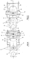
- Fig. 1 is a side elevation view, partially sectioned along the line I-I of Fig. 3, showing the device for reciprocating the coffee feeding carriage;
- Fig. 2 is a plan view of the motor associated to the coffee feeding carriage together with the two disc cam controlling the stop microswitches of the motor;
- Fig. 3 is a plan view of the carriage crank mechanism and the coffee feeding carriage in the coffee loading-disposal station;
- Fig. 4 is a view similar to Fig. 3 showing the coffee feeding carriage in the coffee infusion station;
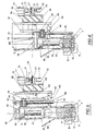
- Fig. 5 is a side elevation view showing the device for loading, pressing and disposing off the ground coffee;
- Fig. 6 is a plan view of the motor associated to the coffee pressing piston together with the two disc cam controlling the stop microswitches of the motor;
- Fig. 7 is a sectional view, taken along the line VII-VII of Fig. 5, of the device for loading, pressing and disposing off the coffee with the pressing piston in its rest position in which the coffee loading operation occurs; and
- Fig. 8 is a view similar to Fig. 7 showing the coffee pressing piston in the active position in which the ground coffee pressing and disposal operation occurs
- Figs. 1 to 4 show the device for feeding the ground coffee from the coffee loading station to the coffee infusion station. For this purpose, a coffee feeding carriage, generally designated with 10, is used. This carriage slides between two pairs of
guides 11 and 12 (Figs. 3 and 4) from a station A wherein it is in the ground coffee loading and disposal station to a station B wherein it is in the coffee infusion station, above the delivery opening 9. In the carriage 10 areceptacle 13 is provided for receiving the ground coffee coming from the conventional coffee mill (not shown). - In the station A the
receptacle 13 of thecarriage 10 is located below thecylindrical chamber 14 for receiving the ground coffee and in which the pressing piston of the espresso coffee machine reciprocates. In the station A thereceptacle 13 of thecarriage 10 is also located above the opening 15 for disposing off the coffee grounds. - The
carriage 10 is connected at its rear end to a crank mechanism, generally designated with 20, through arod 16 the free end of which is adjustable by anut 17 screwed on a threaded portion thereof and pivotally connected to the carriage by means of anancor pin 18 connected to the carriage by means of nuts 19 (Figs. 3 and 4). - The
crank mechanism 20 comprises acrank wheel 21 having acrank pin 22 on which a bushing 23 freely rotates and a slottedlink 24 formed of a pair of plates connected to each other at the ends by bushings. The ends of the slottedlink 24 slide on a pair of rods 25 (as can best seen in Figs. 3 and 4) which are fastened to the machine frame T. - The
crank wheel 21 is fastened by ascrew 26 to thelower end 27 of the output shaft of a reducinggear 28 driven by anelectric motor 40, whereas to theupper end 29 of the output shaft of the reducing gear 28 a cam means is fastened, generally designated with 30. This cam means comprises twoparallel cam discs notch cam discs arm 35 of amicroswitch - As already said, the unit for preparing the espresso coffee has two work stations, namely the station A wherein the coffee loading and disposal operations occur and a station B wherein the coffee infusion operation occurs. The ground coffee is transferred from the station A to the station B and then, after the infusion operation has been carried out, again in the station A by means of the
carriage 10. - In the station A the ground coffee coming from a coffee mill (not shown) is entered in the
cylindrical chamber 14 in the desired amount and then is pressed in thereceptacle 13 of thecarriage 10 by the coffee loading, pressing and disposal device which will be described later. The ground coffee so pressed in thereceptacle 13 of thecarriage 10 and designated with C, ejects the coffee ground cake P remained in this receptacle after the coffee infusion operation, through the disposal opening 15 - At this point, the
motor 40 is energized which, through the reducinggear 28 and thelower end 27 of its output shaft, rotates thecrank wheel 21 thepin 22 of which, by sliding in theslotted link 24 through therotating bushing 23, causes the back movement of thecar riage 10 to the coffee infusion station B. Together with thecrank wheel 21 also thecam discs upper end 29 of the output shaft of the reducinggear 28. The cam disc rotation causes the alternate actuation of themicroswitches motor 40 when thecarriage 10 is in the stations A and B, respectively. In the station B, thearm 35 of themicroswitch 37 will snap in thenotch 34 of thecam disc 32, so that themotor 40 will be de-energized for maintaining thecarriage 10 in this station. - When the coffee infusion operation has been carried out, another electric signal (supplied by conventional electric or electronic controls which the espresso coffee machine is provided with) will energize again the
motor 40 which, through the reducinggear 28, will rotate again its output shaft by 180° until thearm 35 of themicroswitch 36 will snap in thenotch 33 of thecam disc 31. In the meantime thecrank wheel 21, after having rotated by 180°, will have returned thecarriage 10 in the station A together with the coffee ground cake P contained in thereceptacle 13. - At this point, after having disposed off the coffee ground cake P through the disposal opening 15 and loaded fresh ground coffee C, the
carriage 10 is again returned in the station B and this reciprocating movement of the carriage will be repeated all the times the machine is to deliver espresso coffee. The timing of the device components is carried out by adjusting the position of thecam discs microswitches - Figs 5 to 8 show the device for loading and pressing the coffee before the coffee infusion operation as well as for disposing off the coffee grounds after the coffee infusion operation. For this purpose, a coffee pressing piston, generally designated with 50, is used. This piston slides with its upper portion in a
cylindrical chamber 51 and with its lower portion in acylindrical chamber 54 from a rest station D wherein the loading operation of the ground coffee occurs to a pressing station A wherein the pressing operation of the ground coffee occurs. Below the lowercylindrical chamber 54 in which thepressing piston 50 slides, thecoffee feeding carriage 10 is arranged. Thiscarriage 10 through itsreceptacle 13 receives the ground coffee coming from the coffee mill (not shown). To this purpose, thereceptacle 13 of thecarriage 10 is located below thecylindrical chamber 54 and the opening 15 for disposing off the coffee grounds. Provided in the lowercylindrical chamber 54 is an opening 69 for receiving the ground coffee coming from the coffee mill and/or a loading hopper 41 through which the ground coffee can be introduced. - The
pressing piston 50 is connected at its upper end to a crank mechanism, generally designated with 60, through a stirrup 56 (Figs. 7 and 8) which is connected to the slottedlink 64 of the crank mechanism by anut 57 and to the piston head by a pair ofnuts 58. Thestirrup 56 vertically slides in aslot 59 provided in the side wall of the uppercylindrical chamber 51. Of course, between theslotted link 64 and the stirrup 56 conventional means are provided for adjusting the position of thepressing piston 50 for causing the lower surface of the pressing piston in the station A to be moved exactly to the level of the upper surface of thecarriage 10 in order to introduce all the ground coffee in the carriage receptacle 53. - The
crank mechanism 60 comprises acrank wheel 61 having acrank pin 62 on which a bushing 63 freely rotates and the slottedlink 64 provided with aguide pin 65 which slides in abore 66 of the machine frame T (as can best seen in Figs. 7 and 8). Thebore 66, together with thepin 65 and theslot 59 in which thestirrup 56 slides, acts as a guide for the reciprocating movement of thepressing piston 50. - The
crank wheel 61 is fastened to the left end (not shown in the drawing) of the output shaft of a reducinggear 68 driven by anelectric motor 80, whereas to theright end 67 of the output shaft of the reducing gear 68 a cam means is fastened, generally designated with 70. This cam means has twoparallel cam discs notch cam discs arm microswitch - Also this device has two stations, namely the rest station D in which the ground coffee loading operation occurs and the active station A in which the coffee pressing and disposal operation occurs.
- In the station D of the
pressing piston 50 the ground coffee coming from the coffee mill (not shown) is entered in thecylindrical chamber 54 in the desired amount, through theopening 69 or from the suitable hopper 41. The ground coffee C falls down on the cake P of the coffee grounds in thereceptacle 13 of the slidingcarriage 10. - At this point, the
motor 80 is energized which, through the reducinggear 68 and the left end of its output shaft, rotates thecrank wheel 61 thepin 62 of which, by sliding in the slottedlink 64 through the rotatingbushing 63, causes the down movement of thepressing piston 50 to the active station A, in which the pressing and disposal operations occur. Together with thecrank wheel 61 also thecam discs gear 68. The cam disc rotation causes the alternate actuation of themicroswitches motor 80 when thepressing piston 50 is in the stations A and D, respectively. In the station A, thearm 75 of theswitch 77 will snap in thenotch 73 of thecam disc 71, so that themotor 80 will be deenergized for maintaining thepressing piston 50 in the pressing station A. In the station A thepressing piston 50 causes also the coffee ground cake P to be disposed off through thedisposal opening 15. - When the coffee pressing operation has been carried out, another electric signal (supplied from conventional electric or electronic controls of which the espresso coffee machine is provided) will energize again the
motor 80 which, through the reducinggear 68, will rotate again its output shaft by 180° until thearm 76 of themicroswitch 78 will snap in thenotch 74 of thecam disc 72. In the meantime thecrank wheel 61 after having rotated by 180°, will have lifted thepressing piston 50 again in the station D, in which the new coffee loading operation can occur. - During the loading, pressing and disposal operations the
carriage 10 will be in the advanced position wherein itsreceptacle 13 is aligned with both the lowercylindrical chamber 54 and thedisposal opening 15 whereas during the coffee infusion operation thecarriage 10 will be in its retracted position wherein itsreceptacle 13 is aligned with thedisposal opening 15 and thepressing piston 50 will be in the lifted rest position at the station D, as indicated in Fig. 7. - The timing of the components of this device is carried out by adjusting the position of the
cam discs microswitches - After the disposal operation of the coffee grounds P, the
pressing piston 50 is returned in the rest position D in which the new ground coffee loading operation occurs and this movement of thepressing piston 50 is repeated all the times the coffee machine requires an espresso coffee delivery - From the foregoing it will be easily apparent that the apparatus for loading, pressing, feeding and disposing off the ground coffee according to the present invention is very simple since it is comprised of simple mechanical components which do not substantially require servicing so that the espresso coffee machine incorporating this apparatus is very inexpensive. Furthermore, with the apparatus according to the invention all the disadvantages bonded to the known apparatus of this type have been eliminated.
Claims (8)
1) Apparatus for loading, pressing, feeding and disposing off the ground coffee in automatic espresso coffee machines, of the type having a coffee feeding carriage and a coffee pressing piston movable in a cylinder, characterized in that it comprises:
- first and second crank mechanisms connected to the coffee feeding carriage and the coffee pressing piston, respectively;
- first and second motors for driving the first and second crank mechanisms, respectively;
- cam means associated to each of the first and second crank mechanism actuating motors for controlling the positioning of the coffee feeding carriage in the coffee loading and disposal station and in the coffee infusion station, respectively and for controlling the positioning of the pressing piston in the coffee pressing and disposal station and in the rest station, respectively; and
- control means for energizing said first and second crank mechanism actuating motors at the end of the coffee loading and disposal operation and of the coffee infusion operation of the carriage, respectively and at the end of the coffee pressing and disposal operation and the coffee loading and pressing operation of the pressing piston, respectively.
2) Apparatus according to claim 1, characterized in that each of said crank mechanisms comprises a crank wheel and a slotted link sliding on guide means.
3) Apparatus according to claim 2, characterized in that said guide means of the feeding carriage are formed of two pairs of aligned blocks.
4) Apparatus according to claim 2, characterized in that said guide means of the slotted link of the crank mechanism of the pressing piston are formed of a rod sliding in a bore of the apparatus frame and of a stirrup connected to the pressing piston head and sliding in a vertical slot of the cylinder in which the pressing piston reciprocates.
5) Apparatus according to claim 1, characterized in that said cam means comprise a pair of cam discs each provided with a pair of notches offset by 180° with respect to each other.
6) Apparatus according to claim 1, characterized in that said control means for actuating said crank mechanism actuating motors comprise a pair of microswitches each of which is intended to cooperate with one of said cam discs and to break the energisation of the motors controlling the crank mechanisms when said feeding carriage is in the loading and disposal station and in the infusion station, respectively and said pressing piston is in the pressing and disposal station and in the rest station, respectively.
7) Apparatus according to claim 2, characterized in that said slotted link of each crank mechanisms is formed of a pair of parallel bars connected to each other at both the ends by spacing elements.
8) Apparatus according to claim 7, characterized in that said spacing elements of the slotted link of the feeding carriage are formed by sliding bushings.
Applications Claiming Priority (4)
| Application Number | Priority Date | Filing Date | Title |
|---|---|---|---|
| IT2101488U IT213990Z2 (en) | 1988-04-01 | 1988-04-01 | COMPRESSION MECHANISM, LOADING AND UNLOADING OF GROUND COFFEE ON AUTOMATIC MACHINES FOR ESPRESSO COFFEE. |
| IT2101388U | 1988-04-01 | ||
| IT2101388U IT213955Z2 (en) | 1988-04-01 | 1988-04-01 | MOVEMENT MECHANISM FOR FEEDER TROLLEY ON AUTOMATIC ESPRESSO COFFEE MACHINES. |
| IT2101488U | 1988-04-01 |
Publications (1)
| Publication Number | Publication Date |
|---|---|
| EP0335325A1 true EP0335325A1 (en) | 1989-10-04 |
Family
ID=26327731
Family Applications (1)
| Application Number | Title | Priority Date | Filing Date |
|---|---|---|---|
| EP89105448A Withdrawn EP0335325A1 (en) | 1988-04-01 | 1989-03-28 | Apparatus for loading, pressing, feeding and disposing off the ground coffee in automatic espresso coffee machines |
Country Status (4)
| Country | Link |
|---|---|
| US (1) | US4936199A (en) |
| EP (1) | EP0335325A1 (en) |
| AU (1) | AU608963B2 (en) |
| CA (1) | CA1308563C (en) |
Families Citing this family (9)
| Publication number | Priority date | Publication date | Assignee | Title |
|---|---|---|---|---|
| US5272961A (en) * | 1988-10-17 | 1993-12-28 | The R/M Trust Company | Apparatus for providing french fried potatoes |
| IT1236088B (en) * | 1989-11-28 | 1992-12-22 | Spidem Srl | METHOD TO OBTAIN HOT DRINKS OF SOLUTION AND DEVICE TO IMPLEMENT THE SAID METHOD |
| CH684156A5 (en) * | 1990-10-25 | 1994-07-29 | Armellin S A | Automatic machine for preparing coffee infusions and actuation process. |
| US5372728A (en) * | 1993-01-22 | 1994-12-13 | Bunn-O-Matic Corporation | Grounds removal mechanism |
| US5697288A (en) * | 1996-04-29 | 1997-12-16 | King; Alan M. | Encapsulating coffee between two layers of paper |
| US6260475B1 (en) * | 2000-10-26 | 2001-07-17 | Clio Tegel | Manually operated coffee bean press |
| EP1532903A1 (en) * | 2003-11-20 | 2005-05-25 | Steiner AG Weggis | Exractiondevice for making coffee for a coffee machine |
| US9060645B2 (en) * | 2010-02-02 | 2015-06-23 | Uniterra, Inc. | Beverage brewing device and method |
| CH706100A1 (en) * | 2012-02-08 | 2013-08-15 | Wmf Wuerttemberg Metallwaren | Coffee grinder and removable filter holder and method for operating such a coffee maker. |
Citations (6)
| Publication number | Priority date | Publication date | Assignee | Title |
|---|---|---|---|---|
| US2978974A (en) * | 1958-12-09 | 1961-04-11 | Coffee Equipment Inc | Reciprocating coffee brewer |
| FR2267073A1 (en) * | 1974-04-11 | 1975-11-07 | Imd | |
| FR2447702A1 (en) * | 1979-01-31 | 1980-08-29 | Nocentini Irma | Coin operated coffee making machine - uses programmed disc to control motor driven assembly on curved ramp (PT 16.6.80) |
| WO1982003758A1 (en) * | 1981-04-28 | 1982-11-11 | Wendler Albert | Compact type machine for automatic preparation of so-called expresso coffee from grain coffee |
| DE3529544A1 (en) * | 1984-09-14 | 1986-01-16 | Franke AG, Aarburg | Expresso coffee machine |
| US4709625A (en) * | 1986-10-22 | 1987-12-01 | Gross-Given Manufacturing Co. | Dispensing machine for tea |
Family Cites Families (2)
| Publication number | Priority date | Publication date | Assignee | Title |
|---|---|---|---|---|
| US2907266A (en) * | 1957-01-22 | 1959-10-06 | Automatic Entpr Inc | Automatic coffee brewer with coincontrolled apparatus |
| US3203340A (en) * | 1963-02-01 | 1965-08-31 | Advance Engr Co | Beverage brewing and dispensing mechanism |
-
1989
- 1989-03-27 US US07/329,382 patent/US4936199A/en not_active Expired - Fee Related
- 1989-03-28 EP EP89105448A patent/EP0335325A1/en not_active Withdrawn
- 1989-03-31 CA CA000595409A patent/CA1308563C/en not_active Expired - Lifetime
- 1989-03-31 AU AU32294/89A patent/AU608963B2/en not_active Ceased
Patent Citations (6)
| Publication number | Priority date | Publication date | Assignee | Title |
|---|---|---|---|---|
| US2978974A (en) * | 1958-12-09 | 1961-04-11 | Coffee Equipment Inc | Reciprocating coffee brewer |
| FR2267073A1 (en) * | 1974-04-11 | 1975-11-07 | Imd | |
| FR2447702A1 (en) * | 1979-01-31 | 1980-08-29 | Nocentini Irma | Coin operated coffee making machine - uses programmed disc to control motor driven assembly on curved ramp (PT 16.6.80) |
| WO1982003758A1 (en) * | 1981-04-28 | 1982-11-11 | Wendler Albert | Compact type machine for automatic preparation of so-called expresso coffee from grain coffee |
| DE3529544A1 (en) * | 1984-09-14 | 1986-01-16 | Franke AG, Aarburg | Expresso coffee machine |
| US4709625A (en) * | 1986-10-22 | 1987-12-01 | Gross-Given Manufacturing Co. | Dispensing machine for tea |
Also Published As
| Publication number | Publication date |
|---|---|
| CA1308563C (en) | 1992-10-13 |
| US4936199A (en) | 1990-06-26 |
| AU3229489A (en) | 1989-10-05 |
| AU608963B2 (en) | 1991-04-18 |
Similar Documents
| Publication | Publication Date | Title |
|---|---|---|
| US4852472A (en) | Apparatus for preparing coffee | |
| US4015494A (en) | Cold cut slicing system | |
| EP0335325A1 (en) | Apparatus for loading, pressing, feeding and disposing off the ground coffee in automatic espresso coffee machines | |
| US2812792A (en) | Sliced product measuring and segregating apparatus | |
| US3893357A (en) | Process for cutting reinforcing steel bars for steel concrete and a bar cutting machine for effecting the process | |
| US2260843A (en) | Centerless grinding machine | |
| EP0175431B1 (en) | Automatic lens grinding apparatus | |
| US4046041A (en) | Clamping and feeding device for cold saws | |
| GB2171593A (en) | Beverage brewing apparatus | |
| US3844069A (en) | Automatic loading mechanism and grinding machine | |
| US3956948A (en) | Sharpening machine for root-cutter knives | |
| GB976647A (en) | Centreless grinding machine | |
| GB1474506A (en) | ||
| US2922280A (en) | Hydraulic feed arrangement | |
| US4191078A (en) | Wire cutting flying shear | |
| US3954035A (en) | Slicing machine having feed means synchronized with knife rotation | |
| GB2159392A (en) | Beverage brewing apparatus | |
| US2509771A (en) | Electrically operated automatic cushion filling machine | |
| GB2052375A (en) | Power frame saw | |
| SU1710279A1 (en) | Feeder for blanks | |
| DE4400262A1 (en) | Empty yarn tube handling machine | |
| US2655773A (en) | Apparatus for feeding cylindrical workpieces into centerless-grinding machines | |
| US3865288A (en) | Apparatus for manufacturing slide covers | |
| GB1596579A (en) | Machine for cutting the lead ends of components mounted at printed-wiring boards | |
| US3023548A (en) | Automatic contour edge grinder |
Legal Events
| Date | Code | Title | Description |
|---|---|---|---|
| PUAI | Public reference made under article 153(3) epc to a published international application that has entered the european phase |
Free format text: ORIGINAL CODE: 0009012 |
|
| AK | Designated contracting states |
Kind code of ref document: A1 Designated state(s): AT BE CH DE ES FR GB GR LI LU NL SE |
|
| 17P | Request for examination filed |
Effective date: 19900221 |
|
| 17Q | First examination report despatched |
Effective date: 19911220 |
|
| STAA | Information on the status of an ep patent application or granted ep patent |
Free format text: STATUS: THE APPLICATION IS DEEMED TO BE WITHDRAWN |
|
| 18D | Application deemed to be withdrawn |
Effective date: 19930504 |