EP0878158A2 - Apparatus for preparing coffee having a small-bubbled foam layer. - Google Patents
Apparatus for preparing coffee having a small-bubbled foam layer. Download PDFInfo
- Publication number
- EP0878158A2 EP0878158A2 EP98201517A EP98201517A EP0878158A2 EP 0878158 A2 EP0878158 A2 EP 0878158A2 EP 98201517 A EP98201517 A EP 98201517A EP 98201517 A EP98201517 A EP 98201517A EP 0878158 A2 EP0878158 A2 EP 0878158A2
- Authority
- EP
- European Patent Office
- Prior art keywords
- liquid
- buffer reservoir
- coffee extract
- coffee
- container
- Prior art date
- Legal status (The legal status is an assumption and is not a legal conclusion. Google has not performed a legal analysis and makes no representation as to the accuracy of the status listed.)
- Granted
Links
Images


Classifications
-
- A—HUMAN NECESSITIES
- A47—FURNITURE; DOMESTIC ARTICLES OR APPLIANCES; COFFEE MILLS; SPICE MILLS; SUCTION CLEANERS IN GENERAL
- A47J—KITCHEN EQUIPMENT; COFFEE MILLS; SPICE MILLS; APPARATUS FOR MAKING BEVERAGES
- A47J31/00—Apparatus for making beverages
- A47J31/24—Coffee-making apparatus in which hot water is passed through the filter under pressure, i.e. in which the coffee grounds are extracted under pressure
- A47J31/30—Coffee-making apparatus in which hot water is passed through the filter under pressure, i.e. in which the coffee grounds are extracted under pressure with hot water under steam pressure
-
- A—HUMAN NECESSITIES
- A47—FURNITURE; DOMESTIC ARTICLES OR APPLIANCES; COFFEE MILLS; SPICE MILLS; SUCTION CLEANERS IN GENERAL
- A47J—KITCHEN EQUIPMENT; COFFEE MILLS; SPICE MILLS; APPARATUS FOR MAKING BEVERAGES
- A47J31/00—Apparatus for making beverages
- A47J31/44—Parts or details or accessories of beverage-making apparatus
- A47J31/4496—Means to produce beverage with a layer on top, e.g. of cream, foam or froth
-
- A—HUMAN NECESSITIES
- A47—FURNITURE; DOMESTIC ARTICLES OR APPLIANCES; COFFEE MILLS; SPICE MILLS; SUCTION CLEANERS IN GENERAL
- A47J—KITCHEN EQUIPMENT; COFFEE MILLS; SPICE MILLS; APPARATUS FOR MAKING BEVERAGES
- A47J31/00—Apparatus for making beverages
- A47J31/44—Parts or details or accessories of beverage-making apparatus
- A47J31/46—Dispensing spouts, pumps, drain valves or like liquid transporting devices
- A47J31/462—Dispensing spouts, pumps, drain valves or like liquid transporting devices with an intermediate liquid storage tank
- A47J31/465—Dispensing spouts, pumps, drain valves or like liquid transporting devices with an intermediate liquid storage tank for the heated water
-
- A—HUMAN NECESSITIES
- A47—FURNITURE; DOMESTIC ARTICLES OR APPLIANCES; COFFEE MILLS; SPICE MILLS; SUCTION CLEANERS IN GENERAL
- A47J—KITCHEN EQUIPMENT; COFFEE MILLS; SPICE MILLS; APPARATUS FOR MAKING BEVERAGES
- A47J31/00—Apparatus for making beverages
- A47J31/44—Parts or details or accessories of beverage-making apparatus
- A47J31/46—Dispensing spouts, pumps, drain valves or like liquid transporting devices
- A47J31/462—Dispensing spouts, pumps, drain valves or like liquid transporting devices with an intermediate liquid storage tank
- A47J31/467—Dispensing spouts, pumps, drain valves or like liquid transporting devices with an intermediate liquid storage tank for the infusion
Definitions
- the invention relates to an apparatus for preparing coffee extract having a small-bubbled foam layer, comprising at least one inlet for coffee extract and one outflow opening for discharging coffee extract having a small-bubbled foam layer, the inlet being provided with at least one spout opening for generating a coffee extract jet when coffee extract is fed to the inlet.
- the invention also relates to a Neopolitana apparatus for preparing coffee extract, comprising a hermetically closable liquid container, a coffee container which can be filled with ground coffee, a liquid-conveying tube which is on one side connected to the coffee container and on the other side comprises an open end located adjacent a bottom of the liquid container and an outlet for dispensing the coffee extract, the outlet being in fluid connection with the coffee container such that, in use, the ground coffee is located in the liquid flow path extending from the liquid container to the outlet.
- the invention moreover relates to a method of preparing coffee extract by means of a Neopolitana apparatus comprising a filling chamber to be filled with liquid for forming coffee extract from this liquid.
- Such apparatus is inter alia known from international patent application WO 95/16377.
- a small-bubbled foam layer is obtained by the increased speed of the liquid jet.
- the liquid flows directly from the outlet to the outflow opening.
- the character of the small-bubbled foam layer obtained i.e. the distribution of the size of the different bubbles, proves to be little uniform and predictable.
- it is also known to provide the outflow opening, rather than the inlet, with a spout opening. Accordingly, the apparatus spouts directly into, for instance, a cup.
- this variant also has the above-outlined drawbacks.
- the object of the invention is to meet this problem and is characterized in that in the liquid flow path extending between the spout opening and the outflow opening, a buffer reservoir is incorporated, spaced from the spout opening and the outflow opening, the buffer reservoir being positioned such that, in use, the coffee extract jet from the outlet spouts into a liquid surface of coffee extract already received in the buffer reservoir.
- the spout opening of the inlet generates a coffee extract jet.
- This coffee extract jet ends up in the buffer reservoir, so that the buffer reservoir will be filled with a quantity of coffee extract. Due to the fact that the coffee extract jet spouts into the liquid surface of the meanwhile filled buffer reservoir, bubbles will be formed in the buffer reservoir. At the same time, at least a portion of the coffee extract having bubbles will flow from the buffer reservoir to subsequently flow from the apparatus via the outflow opening. Since the liquid jet spouts into the buffer reservoir, a small-bubbled foam layer is obtained whose properties are predetermined.
- the apparatus is connected to a high-pressure coffee apparatus.
- the coffee apparatus feeds hot water to the coffee filter in the apparatus.
- the coffee filter In the coffee filter, the ground coffee is compressed to form a compact whole.
- the coffee extract is forced out via the openings in the bottom of the coffee filter.
- bubbles are formed in a space between the bottom of the coffee filter and the top wall of the spherical cover. Bubbles smaller than the section of the orifices of the spherical cover can then flow away from the apparatus via the outflow openings in the bottom.
- a coffee extract is dispensed which can be received in a cup disposed under the assembly.
- a foam layer will be present on the coffee extract.
- a drawback of the assembly known from Gebrauchsmuster 29502575 is that for forming the bubbles, it is necessary to build up a high pressure in the apparatus. This implies that for pressurizing the apparatus, relatively expensive means, such as an electric pump, are required.
- the object of the invention is to provide an apparatus whereby a coffee extract having a small-bubbled foam layer can also be prepared under low pressure.
- the flowing away of coffee extract with bubbles from the buffer reservoir can for instance be effected in that the buffer reservoir overflows.
- the buffer reservoir is provided with at least one run-out opening for discharging coffee extract with a small-bubbled foam layer from the buffer reservoir to the outflow opening. This has the advantage that after the preparation of the coffee extract having a small-bubbled foam layer, no or only little residual liquid stays behind in the buffer reservoir.
- the buffer reservoir is of bowl-shaped design, with the run-out opening provided in a sidewall of the buffer reservoir.
- the buffer reservoir is of bowl-shaped design while a bottom of the buffer reservoir is provided with at least one run-out opening for discharging coffee extract having a small-bubbled foam layer from the buffer reservoir to the outflow opening.
- a buffer reservoir is incorporated into the liquid flow path extending between the spout opening and the outflow opening, which buffer reservoir is spaced from the spout opening and comprises the outflow opening mentioned, while, in use, the buffer reservoir is positioned such that, in use, the coffee extract jet from the spout opening spouts into a liquid surface of coffee extract already received in the buffer reservoir, and the quantity of coffee extract dispensed through the spout opening per unit of time and the quantity of coffee extract flowing from the buffer reservoir via the outflow opening per unit of time are adjusted to each other so that in the buffer reservoir a liquid surface is formed having a height of at least 5 mm.
- the jet striking the bath involves the formation of a small-bubbled foam layer. Via the outflow openings, this small-bubbled foam layer is entrained with the rest of the coffee extract to subsequently flow into a container.
- the quantity of coffee extract dispensed through the spout opening per unit of time and the quantity of coffee extract flowing via the outflow opening from the buffer-reservoir per unit of time are adjusted to each other so that in the buffer reservoir a liquid surface is formed having a height of at least 8 mm.
- the apparatus further comprises a Neopolitana unit for preparing the coffee extract, the Neopolitana unit being in fluid connection with the inlet.
- the Neopolitana unit has the characteristic feature of dispensing a coffee extract under a relatively low pressure of, for instance, 0.4 atmosphere. In combination with the spout opening of the inlet and the buffer reservoir, this low pressure is sufficient for obtaining a coffee extract having a small-bubbled foam layer.
- the Neopolitana unit preferably comprises a hermetically closable liquid container, a coffee container that can be filled with ground coffee, a liquid-conveying tube connected on one side to the coffee container and comprising on the other side an open end located adjacent a bottom of the liquid container, the inlet with the spout opening being in fluid connection with the coffee container such that, in use, the ground coffee is located in the liquid flow path from the liquid container to the inlet.
- the liquid container comprises means for controlling the ratio between the quantities of liquid and air in the liquid container without changing the quantity of liquid for setting the temperature of the liquid which, in use, is fed to the coffee container.
- the invention also relates to a Neopolitana apparatus characterized in that the liquid container comprises means for controlling the ratio between the. quantities of liquid and air in the liquid container without changing the quantity of liquid for determining the temperature of the liquid which, in use, is fed to the coffee container.
- this method is characterized in that the temperature of the coffee extract is controlled by a selection of the ratio between the quantity of air and the quantity of water present in the filling chamber.
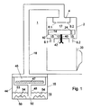
- reference numeral 1 designates an apparatus according to the invention for preparing coffee extract having a small-bubbled foam layer.
- the apparatus comprises a housing 2 with an inlet 4 to which, in use, coffee extract is fed.
- the housing 2 further comprises at least one outflow opening.
- the housing comprises two relatively large outflow openings 6.1 and 6.2.
- the inlet 2 is provided with two relatively small spout openings 8.1 and 8.2. Further, between the spout openings 8.1 and 8.2 on one side and the outflow openings 6.1 and 6.2 on the other, a buffer reservoir 10 is present, spaced from the spout openings 8.1, 8.2 and the outflow openings 6.1 and 6.2.
- the buffer reservoir 10 is incorporated into the liquid flow path extending between the spout openings 8.1 and 8.2 on one side and the outflow openings 6.1 and 6.2 on the other. Between the buffer reservoir and the outflow openings 6.1 and 6.2, an interspace 15 is present.
- the buffer reservoir 10 is of bowl-shaped design and has a flat bottom 12 with vertical sidewalls 14. Between the bottom 12 of the buffer reservoir and the outflow opening, the interspace 15 is present. Also, an interspace 17 is present between the spout openings 8.1 and 8.2 on one side and the buffer reservoir on the other.
- the apparatus of Fig. 1 further comprises a Neopolitana unit 19, to be discussed in more detail hereinbelow, which feeds coffee extract via line 18 to the inlet 4 under a relatively low pressure of, for instance, 0.4 atmosphere.
- the operation of the apparatus is as follows.
- the Neopolitana unit 19 feeds coffee extract to the inlet 4 via line 18, two jets of coffee extract will spout from the spout openings 8.1 and 8.2 respectively.
- the inlet with the spout openings effects an increase of the flow rate relative to the flow rate of the coffee extract in the line 18.
- the surface area of each of the spout openings 8.1 and 8.2 is for instance equal to 0.05-0.5 mm 2 .
- the jets of coffee extract spout-downwards into the buffer reservoir 10. This buffer reservoir 10 will be filled with the coffee extract.
- the coffee extract jets spout with force into the liquid surface of the buffer reservoir 10.
- This coffee extract is also known by the name of 'café crème'.
- the container 20 may consist of a cup or a coffeepot.
- the section of the outflow openings 6.1 and 6.2 is selected so that café crème with the desired bubble size in the small-bubbled foam layer can flow from the housing 2 without the bubbles disappearing.
- the outflow openings 6.1, 6.2 are larger than the desired maximal size of the bubbles in the foam layer.
- the container 20 After the container 20 has been filled with coffee, it can be removed for consumption. In the buffer reservoir, a residual liquid will stay behind, because the buffer reservoir is filled up to the top ends of the vertical sidewalls 14.
- the buffer reservoir 10 is provided with at least one run-out path 22 for discharging coffee extract having a small-bubbled foam layer from the buffer reservoir to the outflow opening.
- Fig. 3 is a top plan view of the buffer reservoir 10 according to Fig. 1 comprising such run-out path 22.
- the run-out path 22 comprises an opening 24 in the vertical sidewall, extending upwards from the bottom 12 of the buffer reservoir 10. This enables the buffer reservoir 10 to drain completely. To ensure that the buffer reservoir 10 does not drain too quickly, so that, in the period when the coffee extract jets spout into the buffer reservoir, a liquid surface can be built up in the buffer reservoir, the run-out path is provided with a predetermined flow resistance 26.
- the flow resistance 26 is formed by a channel formed by vertical sidewalls in the buffer reservoir, with an inlet located in the buffer reservoir and an outlet coinciding with the opening 24 in the vertical sidewall 14 of the buffer reservoir 10.
- the vertical sidewalls 28 of the flow resistance 26 are equally high as the vertical sidewalls 14 of the buffer reservoir 10.
- the channel formed by the vertical sidewalls 28 is of a slightly meandering design, to increase the flow resistance.
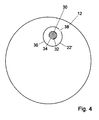
- Fig. 4 again shows the buffer reservoir 10, which, however, now comprises an alternative run-out path 22'.
- the buffer reservoir accordingly comprises an opening 30 provided in the bottom 12.
- a vertical sidewall 32 having an opening 34 extending upwards from the bottom 12.
- the vertical sidewall 32 encloses the opening 30 partially.
- a circular, vertical sidewall 36 also having an opening 38 extending upwards from the bottom 12.
- the vertical sidewall 36 also encloses the opening 30 partially.
- the run-out path 22' extends from the opening 38 to the opening 30 via the circular channel formed between the vertical sidewalls 32 and 36 and via the opening 34.
- the two vertical sidewalls 32 and 36 are equally high and the openings 34 and 38 are located on both sides of the opening 30.
- the vertical sidewalls 32 and 36 are absent, so that only the opening 30 remains. It is also possible that at least one of the vertical sidewalls 32, 36 encloses the opening 30 entirely, so that at least one of the openings 34, 38 is absent.
- the great advantage of the assembly of the inlet 4, the outflow openings 6.1 and 6.2, and the buffer reservoir 10 is that coffee extract having a small-bubbled foam layer can be obtained while coffee extract is fed to the inlet 4 under relatively low pressure.
- the distance between the spout opening and the buffer reservoir is of settable design.
- This can for instance be realized by attaching the buffer reservoir to the housing 2 by means of a spindle 40.
- the housing 2 is provided with an opening having screw thread, which opening having screw thread corresponds to the screw thread of the spindle 40.
- the distance mentioned can be varied.
- the nature of the small-bubbled foam layer formed can be set.
- the size of the bubbles thus proves to be connected with the distance mentioned.
- the distance between the outflow opening and the buffer reservoir is settable as well, while the distance between the spout openings and the outflow openings is fixed.
- the Neopolitana unit 19 of Figs. 1 and 5 comprises a hermetically closable liquid container 44, a coffee container 46 which can be filled with ground coffee 47, and a liquid-conveying tube 48 which is on one side connected to the coffee container 46 and on the other side comprises an open end 52 located adjacent a bottom 50 of the liquid container 44.
- the conveying tube 48 acts as a riser.
- the inlet is in fluid connection with the coffee container 46.
- the ground coffee present in the coffee container will be located in the liquid flow path from the liquid container 44 to the inlet 4.
- the liquid container is filled with water and hermetically closed with the cover-shaped coffee container 46.
- the water level 53 is shown schematically.
- the apparatus further comprises means 54 for controlling the ratio between the quantities of liquid and air in the liquid container 44.
- the liquid container 44 is heated. Heating can be performed with means known per se, such as a flame or an electric heating element. Through heating, the pressure in the liquid container 44 will increase. When the pressure has sufficiently increased, the liquid will be forced upwards through the conveying tube 48. The liquid then flows via the conveying tube 48 through the coffee container 46 filled with ground coffee, to subsequently leave the coffee container as coffee extract and flow, via the line 18, to the inlet 4.
- Heating can be performed with means known per se, such as a flame or an electric heating element.
- the pressure in the liquid container 44 will increase. When the pressure has sufficiently increased, the liquid will be forced upwards through the conveying tube 48. The liquid then flows via the conveying tube 48 through the coffee container 46 filled with ground coffee, to subsequently leave the coffee container as coffee extract and flow, via the line 18, to the inlet 4.
- the initial temperature at which the water starts leaving the liquid container 44 via the conveying tube 48 can be controlled by setting the liquid/water ratio in the liquid container 44, without changing the quantity of water. If it is assumed that the filling height of the liquid container 44 will in each case be approximately the same, this ratio can for instance be set by means of bodies 54 disposed in the liquid container, which are immersed in the liquid. These bodies 54 displace a predetermined quantity of liquid. In the period when the water leaves the Neopolitana unit 19, the air/water ratio will further increase and the temperature of the water leaving the Neopolitana unit 19 will likewise increase.
- the temperature i.e. the variation in temperature of the liquid fed to the coffee container 46, can be controlled in this manner.
- the air/water ratio can also be controlled by varying the quantity of water with which the liquid container 46 is filled.
- the quantity of ground coffee included in the coffee container 46 can for instance be contained in a sachet, the sachet being placed in the coffee container.
- the manner in which the ground coffee is positioned in the coffee container is not relevant to the present invention.
- the coffee container 46 forms a part of the Neopolitana unit.
- the coffee container and the liquid container are integrated into one housing.
- the conveying tube 48 is connected to the coffee container 46 via line 18.
- the coffee container 46 may comprise a cover that can be unscrewed (not shown).
- a one-cup filter 56 known per se is included in the coffee container 46.
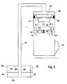
- FIG. 2 It is also possible (Fig. 2) to place in the coffee container 46 a beaker-shaped filter casing known per se, filled with coffee.
- the filter casing has its bottom side provided with a number of very small orifices which are on the one hand permeable to liquid and on the other form a barrier to the ground coffee contained in the filter casing.
- a top wall 58 of the water container 16 of the Neopolitana unit is connected to vertical sidewalls 60 of the water container such that the distance D between the top wall 58 and the bottom 62 is of settable design. With this, the air/water ratio can again be controlled.
- the air/water ratio can also be adjusted during a period in which the water flows from the liquid container. Hence, this permits the temperature of the water leaving the liquid container to be controlled or set at any moment.
- the air/water ratio can then for instance be maintained constant at a predetermined value throughout the period in which the water flows from the liquid container. The above can be realized by readjusting the height D during the period in which the water leaves the Neopolitana unit 19 of Fig. 2.
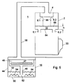
- Fig. 5 shows a third possible embodiment of an apparatus according to the invention.
- parts corresponding to Figs. 1 and 2 are provided with identical reference numerals.
- the buffer reservoir is formed by the housing 2, while the Neopolitana unit corresponds to the Neopolitana unit of Fig. 1.
- a bottom 64 of the housing 2 constitutes the bottom of the buffer reservoir 10.
- the quantity of coffee extract dispensed through the spout openings 8.1 and 8.2 per unit of time and the quantity of coffee extract flowing from the buffer reservoir via the outflow openings 6.1 and 6.2 per unit of time are adjusted to each other so that in the buffer reservoir, a liquid surface 66 is formed having a height h of at least 5 mm.
- the coffee extract contained in the liquid reservoir 10 will leave the buffer reservoir via the outflow openings 6.1 and 6.2. This will involve the formed bubbles leaving the buffer reservoir as well.
- the small-bubbled foam layer is as it were entrained with the coffee extract.
- the height of the liquid surface formed is in particular less than 25 mm. Preferably, this height is less than 15 mm.
- the height h is at least equal to 8 mm, in order that the coffee extract jets can strike the liquid bath, located in the buffer reservoir, over a distance of at least 8 mm.
- the impact over this height of at least 8 mm results in the formation of many bubbles of a uniform character.
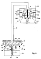
- FIG. 6 a fourth possible embodiment of an apparatus according to the invention is shown.
- parts corresponding to the previous Figures are again provided with identical reference numerals.
- the apparatus according to Figs. 6-9 is provided with an alternative embodiment of the housing 2 with accessories, and with an alternative embodiment of the Neopolitana unit 19.
- the buffer reservoir 10 now comprises first and second run-out paths 22.1 and 22.2.
- the first run-out path 22.1 comprises an opening 24.1 provided in the vertical sidewall 14 of the buffer reservoir 10.
- the first opening 24.1 extends from a top side of the vertical sidewall 14 in the direction of the bottom 12. However, the opening 24.1 does not reach the bottom 12.
- the second run-out path 22.2 comprises a second opening 24.2.
- the second opening 24.2 separated from the first opening 24.1 is designed in the same manner as the first opening 24.1.
- a partition 70 is provided which divides the space within the housing 2 yet outside the buffer reservoir 10 into two separate parts 72.1 and 72.2 respectively, the arrangement being such that the outflow opening 6.1 is in fluid connection with the first part 72.1 of the housing 2. Further, the outflow opening 6.2 is in fluid connection with the second part 72.2 of the housing 2. Further provided in the bottom 12 of the buffer reservoir 10 are a first and a second opening 30.1 and 30.2. The first opening 30.1 forms a fluid connection between the inside of the buffer reservoir 10 and the first part 72.1 of the housing 2. Further, the opening 30.2 provides a fluid connection between the inside of the buffer reservoir 10 and the second part 72.2 of the housing 2.
- the Neopolitana unit 19 feeds coffee extract to the inlet 4 via the line 18, this liquid will be spouted, via the spout openings 8.1 and 8.2, into the buffer reservoir 10, as already discussed hereinabove in relation to the previous Figures.
- the openings 30.1 and 30.2 have such dimensions that per second, more coffee extract is fed to the buffer reservoir via the spout openings 8.1 and 8.2 than is discharged via these openings 30.1 and 30.2.
- the liquid level in the buffer reservoir 10 starts to rise and due to the spouting of the coffee extract into the thus formed liquid surface, a small-bubbled foam layer is formed having a height of, for instance, at least 8 mm.
- the level in the buffer reservoir 10 will eventually increase up to the bottom side of the openings 24.1 and 24.2. After this, the coffee extract with the small-bubbled foam layer will flow, via the opening 24.1, to the portion 72.1 of the container. At the same time, via the opening 24.2, the coffee extract with the small-bubbled foam layer will flow to the portion 72.2 of the container 2.
- the liquids leaving the buffer reservoir 10 via the openings 24.1 and 24.2 remain separated from each other. Consequently, by the buffer reservoir 10, two separate flows of liquid are developed.
- the liquid flowing from the opening 24.1 will eventually leave the container 2 via the outflow opening 6.1. Further, the liquid flowing from the opening 24.2 will leave the container 2 via the outflow opening 6.2.
- two containers 20.1 and 20.2 can be filled with coffee extract.
- a great advantage of the above-discussed embodiment is that the two containers 20.1 and 20.2 will be filled very accurately and to an equal extent with coffee extract having a small-bubbled foam layer.
- the buffer reservoir 10 drains via the openings 30.1 and 30.2.
- the liquid leaving the buffer reservoir 10 via the opening 30.1 will end up in the container 20.1 via the outflow opening 6.1.
- the liquid leaving the buffer reservoir 10 via the opening 30.2 will end up in the container 20.2 via the outflow opening 6.2.
- the apparatus is hence provided with the first and second outflow openings which are positioned relative to the first and second run-out paths so that the buffer reservoir comprises a first and a second run-out path for discharging coffee extract from the buffer reservoir, and that the apparatus is provided with a first and a second outflow opening which are positioned relative to the first and second run-out paths so that the coffee extract with the small-bubbled foam layer leaving the buffer reservoir via the first run-out path is fed to the first outflow opening, and the coffee extract with the small-bubbled foam layer leaving the buffer reservoir via the second run-out path is fed to the second outflow opening.
- Figs. 6-9 is also provided with a particular embodiment of a Neopolitana unit 19.
- the Neopolitana unit 19 comprises a liquid container 44.
- the liquid container 44 comprises a bowl-shaped container 72.
- the bowl-shaped container 72 further includes a shell-shaped element 74 for telescopic up and down movement.
- an annular seal 76 is present between the shell-shaped element 74 and the bowl-shaped container 72.
- the annular seal 76 interconnects the bowl-shaped container 72 and the shell-shaped element 74 so as to be liquidtight and movable up and down in vertical direction.
- the shell-shaped element 74 has its top side bent over outwards in radial direction, to form an annular edge 78. Further, the annular edge 78 has its outer side bent over upwards to form a vertical edge 80 provided with screw thread.
- the Neopolitana unit 19 further comprises a cup-shaped container 82 which, in use, can be filled with coffee.
- the cup-shaped container comprises a perforated sheet 84 on which the ground coffee can be poured.
- the perforated sheet 84 is slightly spaced above a bottom 86 of the cup-shaped container 82.
- the cup-shaped container has its top side provided with an annular edge 88 which extends outwards in radial direction and which, in use, rests on the annular edge 78 of the shell-shaped element 74.
- Located in the bottom 86 is an opening 90 which provides access to a riser 92.
- the riser 92 is composed of an upper riser 94 and a lower riser 96 which is accommodated in the upper riser 94 so as to be telescopically slidable.
- the two risers are again interconnected so as to be liquidtight by a seal not shown.
- a spring arranged around the riser 92, which spring provides that the lower riser 96 is pressed downwards, so that an open end 52 of the riser 92 is located adjacent the bottom 50 of the liquid container 44.
- the Neopolitana apparatus further comprises a cover 100 whose inside is provided with screw thread capable of cooperating with the screw thread of the vertical edge 80. Provided in the cover 100 is an opening 102 connected to the line 18.
- the operation of the Neopolitana apparatus 19 according to Figs. 6-9 is as follows. First of all, the cover 100 is removed. This enables removal of the cup-shaped container 82 together with the riser 92 for filling the container with ground coffee. Next, the liquid container 44 is filled with water up a desired level 102. After this, the cup-shaped container 82, meanwhile filled with ground coffee, located on the perforated sheet 84, is placed back in the tubular element 74. The whole is then closed by means of the cover 100. After this, the volume of the liquid container 44 is set by moving the tubular element 74 in vertical direction up and/or down relative to the cup-shaped container 72. In this manner, the air/water ratio in the liquid container 44 is set.
- the water contained in the Neopolitana unit 19 is heated in a manner known per se.
- the water starts to flow, via the riser 92, in upward direction towards the perforated sheet 84.
- This water then flows through the perforated sheet and through the ground coffee present in the cup-shaped container 82, after which the water leaves the Neopolitana unit via the opening 102 as coffee extract and flows towards the inlet 4 via the line 18.
- the apparatus When the coffee extract has arrived in the inlet 4, the apparatus operates as discussed hereinabove.
- the Neopolitana unit can be filled with a different quantity of liquid.
- the air/water ratio can be adjusted accordingly, so that water is dispensed having the same temperature as discussed hereinabove. It is also possible to set a different temperature by moving the tubular element 74 up and/or down relative to the cup-shaped container 72. Once the water flows from the Neopolitana unit, the air/water ratio in the Neopolitana unit 19 will increase. As a result, the temperature of the water that is dispensed will likewise increase.
- this temperature increase can be corrected by optionally automatically reducing, during the outflow, the total volume of the liquid container and for instance simultaneously limiting and/or breaking off the feed of thermal energy to the water contained in the Neopolitana unit.
- the reduction of the volume mentioned can be effected by moving the shell-shaped element 74 downwards relative to the cup-shaped container 72, optionally in an automatic manner.
- the volume of the liquid container is of controllable design.
- the height of an inner space of the liquid container is settable for controlling the volume of the liquid container, while in the liquid container, a riser is arranged, which riser is of such construction that it extends in vertical direction over a settable distance corresponding to the set height of the liquid container.
- Adjusting the quantity of coffee extract which flows from the buffer reservoir via the outflow opening per unit of time, and the quantity of coffee extract which is dispensed by the spout openings per unit of time can be effected in various manners.
- the number of outflow openings and the sections of the outflow openings can be varied for determining how much coffee extract flows from the buffer reservoir per unit of time.
- the number of spout openings and the sections of the spout openings can be varied for determining how much coffee extract is fed to the buffer reservoir per unit of time.
- the pressure at which the coffee extract is fed to the inlet 4 can be varied for varying the quantity of coffee extract dispensed by the spout openings per unit of time accordingly.
- the surface of the bottom 64 is dimensioned such that the liquid surface of the desired height is obtained.
- the invention is by no means limited to the embodiments described hereinabove.
- the invention relates both to the assembly of inlet, buffer reservoir and outflow openings, and to the Neopolitana unit.
- the invention relates to the combination of the Neopolitana unit and the buffer reservoir.
- the various embodiments described in respect of the assembly on the one hand and the Neopolitana unit on the other may be combined with each other. It will further be understood that on the basis of the description, obvious variants for varying the air/water ratio also belong to the invention.
- the apparatus may also be provided with more inlets having more spout openings and more than one buffer reservoir.
Abstract
Description
Claims (37)
- An apparatus for preparing coffee extract having a small-bubbled foam layer, comprising at least one inlet for coffee extract and at least one outflow opening for discharging coffee extract having a small-bubbled foam layer, the inlet being provided with at least one spout opening for generating a coffee extract jet when coffee extract is fed to the inlet, characterized in that in the liquid flow path extending between the spout opening and the outflow opening, a buffer reservoir is incorporated, spaced from the spout opening and the outflow opening, the buffer reservoir being positioned such that, in use, the coffee extract jet from the spout opening spouts into a liquid surface of coffee extract already received in the buffer reservoir.
- An apparatus according to claim 1, characterized in that an interspace is present between the buffer reservoir and the outflow opening.
- An apparatus according to claim 1 or 2, characterized in that an interspace is present between the buffer reservoir and the spout opening.
- An apparatus according to claim 1, 2 or 3, characterized in that the buffer reservoir comprises at least one run-out path for discharging coffee extract having a small-bubbled foam layer from the buffer reservoir to the outflow opening.
- An apparatus according to any one of claims 1-4, characterized in that the buffer reservoir is of cup-shaped design.
- An apparatus according to claim 5, characterized in that a sidewall of the buffer reservoir is provided with an opening extending upwards from a bottom of the buffer reservoir for discharging coffee extract having a small-bubbled foam layer from the buffer reservoir to the outflow opening.
- An apparatus according to claim 5, characterized in that a bottom of the buffer reservoir is provided with at least one run-out opening for discharging coffee extract having a small-bubbled foam layer from the buffer reservoir to the outflow opening.
- An apparatus according to claim 7, characterized in that the buffer reservoir further comprises a vertical wall which encloses the run-out opening at least partially.
- An apparatus according to any one of claims 4-8, characterized in that the run-out path comprises a liquid flow channel having a predetermined flow resistance.
- An apparatus according to any one of the preceding claims, characterized in that the distance between the spout opening and the buffer reservoir is of settable design.
- An apparatus according to any one of the preceding claims, characterized in that the distance between the outflow opening and the buffer reservoir is of settable design.
- An apparatus according to any one of the preceding claims, characterized in that the distance between the spout opening and the outflow opening is fixed, and the distance between the outflow opening and the buffer reservoir is of settable design.
- An apparatus according to claim 12, characterized in that the quantity of coffee extract dispensed through the inlet per unit of time and the quantity of coffee extract flowing from the buffer reservoir via the outflow opening per unit of time are adjusted to each other such that in the buffer reservoir, a liquid surface is formed having a height of at least 5 mm.
- An apparatus according to any one of the preceding claims, characterized in that the buffer reservoir comprises a first and a second run-out path and that the apparatus comprises a first and a second outflow opening, positioned relative to the first and the second run-out path such that the coffee extract with the small-bubbled foam layer leaving the buffer reservoir via the first run-out path is fed to the first outflow opening, and the coffee extract with the small-bubbled foam layer leaving the buffer reservoir via the second run-out path is fed to the second outflow opening.
- An apparatus for preparing coffee extract having a small-bubbled foam layer, comprising at least one inlet for coffee extract and one outflow opening for discharging coffee extract having a small-bubbled foam layer, the inlet comprising at least one spout opening for generating a coffee extract jet when coffee extract is fed to the inlet, characterized in that a buffer reservoir is incorporated into the liquid flow path extending between the spout opening and the outflow opening, said buffer reservoir being spaced from the spout opening and comprising said outflow opening, while, in use, the buffer reservoir is positioned such that, in use, the coffee extract jet from the spout opening spouts into a liquid surface of coffee extract already received in the buffer reservoir, and the quantity of coffee extract dispensed through the spout opening per unit of time and the quantity of coffee extract flowing from the buffer reservoir via the outflow opening per unit of time are adjusted to each other so that in the buffer reservoir a liquid surface having a height of at least 5 mm is formed.
- An apparatus according to claim 15, characterized in that the quantity of coffee extract dispensed through the spout opening per unit of time and the quantity of coffee extract flowing from the buffer reservoir via the outflow opening per unit of time are adjusted to each other so that in the buffer reservoir a liquid surface having a height of at least 8 mm is formed.
- An apparatus according to claim 15 or 16, characterized in that the height of the liquid surface is less than 25 mm and preferably less than 15 mm.
- An apparatus according to any one of claims 15-17, characterized in that the outflow opening is provided in a bottom of the buffer reservoir.
- An apparatus according to any one of the preceding claims, characterized in that the apparatus further comprises a Neopolitana unit for preparing the coffee extract, the Neopolitana unit being in fluid connection with the inlet.
- An apparatus according to claim 19, characterized in that the Neopolitana unit comprises a hermetically closable liquid container, a coffee container which can be filled with ground coffee, a liquid-conveying tube which is on one side connected to the coffee container and on the other side comprises an open end located adjacent a bottom of the liquid container, the inlet being in fluid connection with the coffee container such that in use, the ground coffee is located in the liquid flow path from the liquid container to the inlet.
- An apparatus according to claim 20, characterized in that the liquid container comprises means for controlling the ratio between the quantities of liquid and air in the liquid container without changing the quantity of liquid for setting the temperature of the liquid which, in use, is fed to the coffee container.
- An apparatus according to claim 21, characterized in that said means consist of at least one body disposed in the liquid container, said body, immersed in liquid, displacing a predetermined quantity of liquid.
- An apparatus according to claim 21, characterized in that the volume of the liquid container is of controllable design.
- An apparatus according to claim 23, characterized in that the height of an inner space of the liquid container is of settable design for controlling the volume of the liquid container.
- An apparatus according to claim 24, characterized in that in the liquid container, a riser is provided, of such design that it extends in vertical direction over a settable distance corresponding to the set height of the liquid container.
- An apparatus according to any one of claims 20-25, characterized in that the coffee container and the liquid container are integrated into one housing.
- An apparatus according to any one of preceding claims 20-26, characterized in that the coffee container, the inlet, the buffer reservoir and the outflow opening are integrated into one housing.
- An apparatus according to any one of preceding claims 20-27, characterized in that the coffee container is arranged for receiving a sachet filled with ground coffee.
- An apparatus according to any one of preceding claims 20-28, characterized in that the coffee container is arranged for receiving a coffee cartridge filled with ground coffee.
- A Neopolitana apparatus for preparing coffee extract, comprising a hermetically closable liquid container, a coffee container which can be filled with ground coffee, a liquid-conveying tube which is on one side connected to the coffee container and on the other side comprises an open end located adjacent a bottom of the liquid container and an outlet for dispensing the coffee extract, the outlet being in fluid connection with the coffee container such that, in use, the ground coffee is located in the liquid flow path extending from the liquid container to the outlet, characterized in that the liquid container comprises means for controlling the ratio between the quantities of liquid and air in the liquid container without changing the quantity of liquid for determining the temperature of the liquid which, in use, is fed to the coffee container.
- An apparatus according to claim 30, characterized in that said means consist of at least one body disposed in the liquid container, said body, immersed in liquid, displacing a quantity of liquid.
- An apparatus according to claim 31, characterized in that the volume of the body is of controllable design.
- An apparatus according to claim 30, characterized in that the volume of the liquid container is of controllable design.
- An apparatus according to claim 33, characterized in that the height of the inner space of the liquid container is of settable design for controlling the volume of the liquid container.
- An apparatus according to claim 34, characterized in that in the liquid container, a riser is provided, designed such that it extends in vertical direction over a settable distance corresponding to the set height of the liquid container.
- A method of preparing coffee extract by means of a Neopolitana apparatus comprising a filling chamber to be filled with liquid for forming coffee extract from said liquid, characterized in that the temperature of the coffee extract is controlled by a selection of the ratio between the quantity of air and the quantity of water present in the filling chamber.
- A method according to claim 36, characterized in that said air/liquid ratio is determined at a moment before the liquid is converted into coffee extract.
Priority Applications (1)
| Application Number | Priority Date | Filing Date | Title |
|---|---|---|---|
| EP01203548A EP1169956A3 (en) | 1997-05-13 | 1998-05-13 | Apparatus for preparing coffee having a small-bubbled foam layer |
Applications Claiming Priority (2)
| Application Number | Priority Date | Filing Date | Title |
|---|---|---|---|
| NL1006039A NL1006039C2 (en) | 1997-05-13 | 1997-05-13 | Device for preparing coffee with a small-bubble froth layer. |
| NL1006039 | 1997-05-13 |
Related Child Applications (1)
| Application Number | Title | Priority Date | Filing Date |
|---|---|---|---|
| EP01203548A Division EP1169956A3 (en) | 1997-05-13 | 1998-05-13 | Apparatus for preparing coffee having a small-bubbled foam layer |
Publications (3)
| Publication Number | Publication Date |
|---|---|
| EP0878158A2 true EP0878158A2 (en) | 1998-11-18 |
| EP0878158A3 EP0878158A3 (en) | 1999-01-27 |
| EP0878158B1 EP0878158B1 (en) | 2002-03-13 |
Family
ID=19764960
Family Applications (2)
| Application Number | Title | Priority Date | Filing Date |
|---|---|---|---|
| EP01203548A Withdrawn EP1169956A3 (en) | 1997-05-13 | 1998-05-13 | Apparatus for preparing coffee having a small-bubbled foam layer |
| EP98201517A Expired - Lifetime EP0878158B1 (en) | 1997-05-13 | 1998-05-13 | Apparatus for preparing coffee having a small-bubbled foam layer. |
Family Applications Before (1)
| Application Number | Title | Priority Date | Filing Date |
|---|---|---|---|
| EP01203548A Withdrawn EP1169956A3 (en) | 1997-05-13 | 1998-05-13 | Apparatus for preparing coffee having a small-bubbled foam layer |
Country Status (11)
| Country | Link |
|---|---|
| US (1) | US6119582A (en) |
| EP (2) | EP1169956A3 (en) |
| JP (1) | JP4344022B2 (en) |
| AT (1) | ATE214249T1 (en) |
| AU (1) | AU739554B2 (en) |
| CA (1) | CA2237447C (en) |
| DE (1) | DE69804146T2 (en) |
| DK (1) | DK0878158T3 (en) |
| ES (1) | ES2174386T3 (en) |
| NL (1) | NL1006039C2 (en) |
| PT (1) | PT878158E (en) |
Cited By (23)
| Publication number | Priority date | Publication date | Assignee | Title |
|---|---|---|---|---|
| NL1016106C2 (en) | 2000-09-05 | 2002-03-07 | Sara Lee De Nv | Device for preparing a coffee extract with a small-bubble froth layer. |
| NL1016107C2 (en) | 2000-09-05 | 2002-03-07 | Sara Lee De Nv | Device for preparing a coffee extract with a small-bubble froth layer. |
| WO2003055366A2 (en) | 2001-12-24 | 2003-07-10 | Koninklijke Philips Electronics N.V. | Beverage device for making a beverage with a foam layer on top |
| NL1020834C2 (en) | 2002-06-12 | 2003-12-15 | Sara Lee De Nv | Device and method for preparing a beverage suitable for consumption with a fine-bubble froth layer. |
| NL1020833C2 (en) | 2002-06-12 | 2003-12-15 | Sara Lee De Nv | Device for preparing a beverage suitable for consumption with a fine-bubble froth layer. |
| NL1020836C2 (en) | 2002-06-12 | 2003-12-15 | Sara Lee De Nv | Device and method for preparing coffee with a fine-bubble froth layer, in particular cappuccino. |
| NL1020837C2 (en) | 2002-06-12 | 2003-12-15 | Sara Lee De Nv | Device and method for preparing coffee with a fine-bubble froth layer, in particular cappuccino. |
| NL1021325C2 (en) | 2002-08-23 | 2004-02-24 | Sara Lee De Nv | Rigid pad for preparing a drink suitable for consumption. |
| EP1498059A1 (en) * | 2003-07-15 | 2005-01-19 | Pav Patentverwertung Kg | Coffee brewer with device for forming bubbles |
| NL1026834C2 (en) | 2004-08-12 | 2006-02-14 | Sara Lee De Nv | Prepare tea using a tea pad and coffee maker. |
| NL1028101C2 (en) | 2005-01-24 | 2006-07-25 | Sara Lee De Nv | Assembly for preparing a beverage suitable for consumption, rigid body of the assembly and method for preparing a beverage suitable for consumption with the assembly. |
| NL1028133C2 (en) | 2005-01-27 | 2006-07-31 | Sara Lee De Nv | Method and device for preparing a drink suitable for consumption. |
| WO2006080844A2 (en) | 2005-01-27 | 2006-08-03 | Sara Lee/De N.V. | Method for preparing a beverage suitable for consumption from at least two ingredients to be dissolved and/or extracted and an amount of liquid |
| WO2006111890A1 (en) * | 2005-04-18 | 2006-10-26 | Koninklijke Philips Electronics N.V. | Coffee maker comprising means for generating a rotation in a flow of beverage |
| WO2007063502A3 (en) * | 2005-12-01 | 2007-09-20 | Koninkl Philips Electronics Nv | A tea making device having an improved liquid collection chamber |
| CN1889875B (en) * | 2003-12-11 | 2010-06-23 | 皇家飞利浦电子股份有限公司 | Device for preparing a beverage suitable for human consumption with a fine-bubble foam layer |
| WO2011113474A1 (en) * | 2010-03-15 | 2011-09-22 | Duizendpoot B.V. | Coffee maker |
| DE102010012788A1 (en) * | 2010-03-16 | 2011-09-22 | Wmf Württembergische Metallwarenfabrik Ag | Espresso machine or coffee machine has brewer and brewing device having brewing chamber filled with coffee powder |
| US8039036B2 (en) | 2003-08-25 | 2011-10-18 | Sara Lee/De N.V. | Preparation of a beverage suitable for consumption |
| US20130230625A1 (en) * | 2006-08-10 | 2013-09-05 | Koninklijke Douwe Egberts B.V. | Pad with covering filled with product to be extracted, assembly of a first and a second pad and method for preparing a small or large amount of beverage |
| US8850960B2 (en) | 2008-01-29 | 2014-10-07 | Koninklijke Douwe Egberts B.V. | System, method and capsule for preparing a beverage |
| US9260238B2 (en) | 2006-08-10 | 2016-02-16 | Koninklijke Douwe Egberts B.V. | Method for providing a beverage provided with a fine-bubble froth layer or a beverage at least virtually without the fine bubble froth layer, pad with covering filled with product to be extracted and/or to be dissolved; assembly provided with such a pad and a holder; beverage preparation apparatus for preparing a beverage |
| US9862537B2 (en) | 2002-08-23 | 2018-01-09 | Koninklijke Douwe Egberts B.V. | Form-retaining pad for preparing a beverage suitable for consumption |
Families Citing this family (30)
| Publication number | Priority date | Publication date | Assignee | Title |
|---|---|---|---|---|
| NL1012847C2 (en) | 1999-08-17 | 2001-02-20 | Sara Lee De Nv | Coffee preparation device. |
| NL1013270C2 (en) * | 1999-10-12 | 2001-04-17 | Sara Lee De Nv | Device for preparing a coffee extract with a fine-bubble froth layer. |
| US6777007B2 (en) * | 2002-07-06 | 2004-08-17 | Edward Z. Cai | Pod and method for making fluid comestible |
| US20060280841A1 (en) * | 2000-12-22 | 2006-12-14 | Cai Edward Z | Drink cartridge and method of manufacturing the same |
| CA2439991C (en) | 2001-03-16 | 2007-05-22 | The Procter & Gamble Company | Beverage brewing devices for preparing creamy beverages |
| WO2003030696A1 (en) * | 2001-10-05 | 2003-04-17 | Hp Intellectual Corp. | Coffee maker |
| CN100411571C (en) * | 2002-09-13 | 2008-08-20 | 皇家飞利浦电子股份有限公司 | Pad support for a beverage maker, foam unit and beverage maker comprising such a pad support, and method of preparing a beverage with a foam layer using such a pad support |
| US6840158B2 (en) | 2002-12-09 | 2005-01-11 | Edward Z. Cai | Device for making coffee drink having a crema layer |
| US7032503B2 (en) * | 2002-12-24 | 2006-04-25 | Household Technology Group Llc | Brew station for coffee drinks |
| US7640843B2 (en) | 2003-01-24 | 2010-01-05 | Kraft Foods R & D, Inc. | Cartridge and method for the preparation of beverages |
| BE1015518A4 (en) | 2003-05-16 | 2005-05-03 | Hoorelbeke Alain | Method and apparatus for foam formation of hot drinks. |
| US6935222B2 (en) * | 2003-07-09 | 2005-08-30 | Electrical And Electronics Limited | Locking device sustaining high pressure for coffee maker lid |
| DE10344328B4 (en) * | 2003-09-24 | 2013-09-12 | WMF Württembergische Metallwarenfabrik Aktiengesellschaft | Coffee brewing device with foaming chamber |
| US7237475B2 (en) | 2003-12-23 | 2007-07-03 | Electrical And Electronics, Limited | Cabinet design of filter holder for pressurized espresso machines |
| US7617763B2 (en) | 2003-12-23 | 2009-11-17 | Electrical & Electronics Limited | Motorized and remote-controlled cabinet design of filter holder for pressurized espresso machines |
| US20090013874A1 (en) * | 2004-02-05 | 2009-01-15 | Koninklijke Philips Electronics N.V. | Beverage Making Device |
| CA2555318A1 (en) * | 2004-02-06 | 2005-08-25 | Bunn-O-Matic Corporation | Apparatus, system and method for retaining beverage brewing substance |
| US7503253B2 (en) * | 2004-02-09 | 2009-03-17 | Bunn-O-Matic Corporation | Apparatus, system and method for infusing a pre-packaged pod |
| ITMO20040202A1 (en) * | 2004-07-30 | 2004-10-30 | Illycaffe Spa | METHODS AND APPARATUS FOR OBTAINING DRINKS. |
| DE102004046450A1 (en) * | 2004-09-24 | 2006-04-06 | BSH Bosch und Siemens Hausgeräte GmbH | Coffee machine with a spout |
| DE102004046458A1 (en) * | 2004-09-24 | 2006-04-06 | BSH Bosch und Siemens Hausgeräte GmbH | Coffee machine with a spout |
| US20060254428A1 (en) * | 2005-05-14 | 2006-11-16 | Glucksman Dov Z | Coffee making apparatus |
| NL1029503C2 (en) * | 2005-07-12 | 2007-01-15 | Sara Lee De Nv | System and method for preparing a beverage suitable for consumption, as well as a use of such a system, a receiving chamber and a container. |
| DE202005011203U1 (en) | 2005-07-16 | 2005-09-22 | Eugster/Frismag Ag | Dispenser for espresso machine comprises two outlet tubes connected by horizontal pipes to central feed pipe, tops of tubes being sealed, forming baffle chambers in which large bubbles in the milk are broken up, improving flow |
| NL1032080C2 (en) * | 2006-04-19 | 2007-10-22 | Sara Lee De Nv | Interchangeable holder for use in an apparatus for preparing a drink suitable for consumption. |
| US20080050496A1 (en) * | 2006-08-25 | 2008-02-28 | Dorin Boldor | Mixing apparatus |
| GB2454656A (en) | 2007-11-09 | 2009-05-20 | Kraft Foods R & D Inc | A beverage cartridge |
| ES2677713T3 (en) | 2009-03-27 | 2018-08-06 | Koninklijke Douwe Egberts B.V. | Beverage dispensing system |
| DE102010004727B4 (en) * | 2010-01-14 | 2014-03-13 | Wmf Ag | Device according to the riser principle for the preparation of a hot beverage |
| CN109984565B (en) * | 2018-01-02 | 2021-09-21 | 佛山市顺德区美的电热电器制造有限公司 | Cooking appliance and vacuum reservation fresh-keeping control method thereof |
Family Cites Families (10)
| Publication number | Priority date | Publication date | Assignee | Title |
|---|---|---|---|---|
| FR1151603A (en) * | 1955-06-14 | 1958-02-03 | Coffee maker for the automatic preparation of infusions of coffee, or similar products | |
| DE3404320A1 (en) * | 1983-03-23 | 1984-09-27 | Alfonso Bialetti & C. S.p.A., Omegna-Crusinallo, Novara | DEVICE DETERMINED FOR HOUSEHOLD USE FOR THE PRODUCTION OF WARM BEVERAGES AND RELATED COFFEE MAKERS |
| GB8507974D0 (en) * | 1985-03-27 | 1985-05-01 | Still & Sons Ltd W M | Coffee & tea making apparatus |
| US4903585A (en) * | 1988-01-04 | 1990-02-27 | Nestec, S.A. | Apparatus for dispensing coffee having a foamed surface |
| DE8913653U1 (en) * | 1989-11-18 | 1990-03-29 | Hirsch, Paul, 8000 Muenchen, De | |
| FR2662594B3 (en) * | 1990-05-30 | 1992-10-09 | Moulinex Sa | FILTER HOLDER FOR COFFEE MACHINE OF THE "ESPRESSO" TYPE. |
| WO1995016377A1 (en) * | 1993-12-13 | 1995-06-22 | Ferr-Max Kft. | Method of and apparatus for preparing a frothy coffee beverage, especially for household use |
| DE29502595U1 (en) * | 1995-02-17 | 1995-03-30 | Eugster Arthur Ag | Calming section for espresso machine filter carriers |
| US5638740A (en) * | 1995-02-24 | 1997-06-17 | Cai; Zhihua | Apparatus for brewing espresso and cappuccino |
| NL1002929C2 (en) * | 1996-04-23 | 1997-10-24 | Sara Lee De Nv | Cartridge holder for preparing a cup of coffee with a small bubble-foam layer. |
-
1997
- 1997-05-13 NL NL1006039A patent/NL1006039C2/en not_active IP Right Cessation
-
1998
- 1998-05-13 PT PT98201517T patent/PT878158E/en unknown
- 1998-05-13 DE DE69804146T patent/DE69804146T2/en not_active Expired - Lifetime
- 1998-05-13 AU AU64882/98A patent/AU739554B2/en not_active Ceased
- 1998-05-13 ES ES98201517T patent/ES2174386T3/en not_active Expired - Lifetime
- 1998-05-13 DK DK98201517T patent/DK0878158T3/en active
- 1998-05-13 AT AT98201517T patent/ATE214249T1/en active
- 1998-05-13 EP EP01203548A patent/EP1169956A3/en not_active Withdrawn
- 1998-05-13 EP EP98201517A patent/EP0878158B1/en not_active Expired - Lifetime
- 1998-05-13 JP JP13068898A patent/JP4344022B2/en not_active Expired - Fee Related
- 1998-05-13 US US09/078,180 patent/US6119582A/en not_active Expired - Lifetime
- 1998-05-13 CA CA002237447A patent/CA2237447C/en not_active Expired - Fee Related
Cited By (62)
| Publication number | Priority date | Publication date | Assignee | Title |
|---|---|---|---|---|
| KR100782427B1 (en) * | 2000-09-05 | 2007-12-05 | 사라 리/디이 엔.브이. | Apparatus for preparing a coffee extract with a fine-bubble froth layer using a liquid flow decelerating barrier |
| US6769352B2 (en) | 2000-09-05 | 2004-08-03 | Sara Lee/De N.V. | Apparatus for preparing a coffee extract with a fine-bubble froth layer using a rough impact surface |
| WO2002019877A1 (en) | 2000-09-05 | 2002-03-14 | Sara Lee/De N.V. | Apparatus for preparing a coffee extract with a fine-bubble froth layer using a rough impact surface |
| WO2002019876A1 (en) | 2000-09-05 | 2002-03-14 | Sara Lee/De N.V. | Apparatus for preparing a coffee extract with a fine-bubble froth layer using a liquid flow decelerating barrier |
| KR100782432B1 (en) * | 2000-09-05 | 2007-12-05 | 사라 리/디이 엔.브이. | Apparatus for preparing a coffee extract with a fine-bubble froth layer using a rough impact surface |
| NL1016106C2 (en) | 2000-09-05 | 2002-03-07 | Sara Lee De Nv | Device for preparing a coffee extract with a small-bubble froth layer. |
| AU2002211054B9 (en) * | 2000-09-05 | 2006-03-09 | Koninklijke Douwe Egberts B.V. | Apparatus for preparing a coffee extract with a fine-bubble froth layer using a rough impact surface |
| AU2001294386B2 (en) * | 2000-09-05 | 2006-02-02 | Koninklijke Douwe Egberts B.V. | Apparatus for preparing a coffee extract with a fine-bubble froth layer using a liquid flow decelerating barrier |
| NL1016107C2 (en) | 2000-09-05 | 2002-03-07 | Sara Lee De Nv | Device for preparing a coffee extract with a small-bubble froth layer. |
| AU2002211054B2 (en) * | 2000-09-05 | 2005-12-22 | Koninklijke Douwe Egberts B.V. | Apparatus for preparing a coffee extract with a fine-bubble froth layer using a rough impact surface |
| US6799504B2 (en) | 2000-09-05 | 2004-10-05 | Sara Lee/De N.V. | Apparatus for preparing a coffee extract with a fine-bubble froth layer using a liquid flow decelerating barrier |
| US7958815B2 (en) | 2001-12-24 | 2011-06-14 | Koninklijke Philips Electronics N.V. | Beverage device for making a beverage with a foam layer on top |
| US7591217B2 (en) | 2001-12-24 | 2009-09-22 | Koninklijke Philips Electronics N.V. | Beverage device for making a beverage with a foam layer on top |
| WO2003055366A2 (en) | 2001-12-24 | 2003-07-10 | Koninklijke Philips Electronics N.V. | Beverage device for making a beverage with a foam layer on top |
| CN1303927C (en) * | 2001-12-24 | 2007-03-14 | 皇家飞利浦电子股份有限公司 | Beverage device for making a beverage with a foam layer on top |
| WO2003105644A1 (en) * | 2002-06-12 | 2003-12-24 | Sara Lee/De N.V. | Apparatus and method for preparing a beverage fit for consumption with a fine-bubble froth layer |
| US7762180B2 (en) | 2002-06-12 | 2010-07-27 | Sara Lee/De N.V. | Apparatus and method for preparing coffee with a fine-bubble froth layer, in particular cappuccino |
| WO2003105641A1 (en) * | 2002-06-12 | 2003-12-24 | Sara Lee/De N.V. | Apparatus and method for preparing coffee with a fine-bubble froth layer, in particular cappuccino |
| WO2003105645A1 (en) * | 2002-06-12 | 2003-12-24 | Sara Lee/De N.V. | Apparatus and method for preparing coffee with a fine-bubble froth layer, in particular cappucino |
| US7455011B2 (en) | 2002-06-12 | 2008-11-25 | Sara Lee/De N.V. | Apparatus and method for preparing coffee with a fine-bubble froth layer, in particular cappuccino |
| US7698993B2 (en) | 2002-06-12 | 2010-04-20 | Sara Lee/De N. V. | Apparatus and method for preparing a beverage fit for consumption with a fine-bubble froth layer |
| EP1371311A1 (en) * | 2002-06-12 | 2003-12-17 | Sara Lee/DE | Apparatus for preparing a beverage suitable for consumption with a fine-bubble foam layer |
| WO2003105642A1 (en) | 2002-06-12 | 2003-12-24 | Sara Lee/De N.V. | Apparatus for preparing a consumable beverage with a fine-bubbled foam layer |
| NL1020837C2 (en) | 2002-06-12 | 2003-12-15 | Sara Lee De Nv | Device and method for preparing coffee with a fine-bubble froth layer, in particular cappuccino. |
| NL1020836C2 (en) | 2002-06-12 | 2003-12-15 | Sara Lee De Nv | Device and method for preparing coffee with a fine-bubble froth layer, in particular cappuccino. |
| NL1020834C2 (en) | 2002-06-12 | 2003-12-15 | Sara Lee De Nv | Device and method for preparing a beverage suitable for consumption with a fine-bubble froth layer. |
| US7748311B2 (en) | 2002-06-12 | 2010-07-06 | Sara Lee/De N.V. | Apparatus for preparing a consumable beverage with a fine-bubbled foam layer |
| NL1020833C2 (en) | 2002-06-12 | 2003-12-15 | Sara Lee De Nv | Device for preparing a beverage suitable for consumption with a fine-bubble froth layer. |
| EP1398279A2 (en) | 2002-08-23 | 2004-03-17 | Sara Lee/DE N.V. | Form-retaining pad for preparing a beverage suitable for consumption |
| WO2004018326A1 (en) | 2002-08-23 | 2004-03-04 | Sara Lee/De N.V. | Form-retaining pad for preparing a beverage suitable for consumption |
| NL1021325C2 (en) | 2002-08-23 | 2004-02-24 | Sara Lee De Nv | Rigid pad for preparing a drink suitable for consumption. |
| US9862537B2 (en) | 2002-08-23 | 2018-01-09 | Koninklijke Douwe Egberts B.V. | Form-retaining pad for preparing a beverage suitable for consumption |
| FR2863593A1 (en) | 2002-08-23 | 2005-06-17 | Sara Lee De Nv | Buffer for preparing drink e.g. coffee, has body with upper and lower sides adjacent to respective upper and lower leaves of cover, and divided into compartments, where each compartment is surrounded by leaves and walls |
| EP1498059A1 (en) * | 2003-07-15 | 2005-01-19 | Pav Patentverwertung Kg | Coffee brewer with device for forming bubbles |
| EP1662952B2 (en) † | 2003-08-25 | 2014-11-19 | Koninklijke Douwe Egberts B.V. | Preparation of a beverage suitable for consumation |
| US8039036B2 (en) | 2003-08-25 | 2011-10-18 | Sara Lee/De N.V. | Preparation of a beverage suitable for consumption |
| US7779749B2 (en) | 2003-12-11 | 2010-08-24 | Koninklijke Philips Electronics N.V. | Device for preparing a beverage suitable for human consumption with a fine-bubble foam layer |
| CN1889875B (en) * | 2003-12-11 | 2010-06-23 | 皇家飞利浦电子股份有限公司 | Device for preparing a beverage suitable for human consumption with a fine-bubble foam layer |
| US8935977B2 (en) | 2003-12-11 | 2015-01-20 | Koninklijke Philips N.V. | Device for preparing a beverage with a foam layer |
| US8257768B2 (en) | 2003-12-11 | 2012-09-04 | Koninklijke Philips Electronics N.V. | Method for preparing a beverage suitable for human consumption with a fine-bubble foam layer |
| NL1026834C2 (en) | 2004-08-12 | 2006-02-14 | Sara Lee De Nv | Prepare tea using a tea pad and coffee maker. |
| US9481506B2 (en) | 2005-01-24 | 2016-11-01 | Koninklijke Douwe Egberts B.V. | Assembly and method for preparing a beverage |
| NL1028101C2 (en) | 2005-01-24 | 2006-07-25 | Sara Lee De Nv | Assembly for preparing a beverage suitable for consumption, rigid body of the assembly and method for preparing a beverage suitable for consumption with the assembly. |
| JP2008528172A (en) * | 2005-01-27 | 2008-07-31 | サラ リー/デーイー エヌ.ヴェー | Method for preparing a beverage suitable for consumption from at least two dissolved components and / or extracted components and a certain amount of liquid |
| WO2006080844A2 (en) | 2005-01-27 | 2006-08-03 | Sara Lee/De N.V. | Method for preparing a beverage suitable for consumption from at least two ingredients to be dissolved and/or extracted and an amount of liquid |
| NL1028133C2 (en) | 2005-01-27 | 2006-07-31 | Sara Lee De Nv | Method and device for preparing a drink suitable for consumption. |
| WO2006080843A2 (en) | 2005-01-27 | 2006-08-03 | Sara Lee/De N.V. | Method and apparatus for preparing a beverage suitable for consumption |
| WO2006111890A1 (en) * | 2005-04-18 | 2006-10-26 | Koninklijke Philips Electronics N.V. | Coffee maker comprising means for generating a rotation in a flow of beverage |
| CN101160081B (en) * | 2005-04-18 | 2011-05-18 | 皇家飞利浦电子股份有限公司 | Coffee maker comprising means for generating a rotation in a flow of beverage |
| US8256343B2 (en) | 2005-04-18 | 2012-09-04 | Koninklijke Philips Electronics N.V. | Coffee maker comprising means for generating a rotation in a flow of beverage |
| CN101321484B (en) * | 2005-12-01 | 2011-03-16 | 皇家飞利浦电子股份有限公司 | A tea making device having an improved liquid collection chamber |
| US8479641B2 (en) | 2005-12-01 | 2013-07-09 | Koninklijke Philips Electronics N.V. | Tea making device having an improved liquid collection chamber |
| US8113106B2 (en) | 2005-12-01 | 2012-02-14 | Koninklijke Philips Electronics N.V. | Tea making device having an improved liquid collection chamber |
| WO2007063502A3 (en) * | 2005-12-01 | 2007-09-20 | Koninkl Philips Electronics Nv | A tea making device having an improved liquid collection chamber |
| US20130230625A1 (en) * | 2006-08-10 | 2013-09-05 | Koninklijke Douwe Egberts B.V. | Pad with covering filled with product to be extracted, assembly of a first and a second pad and method for preparing a small or large amount of beverage |
| US9260238B2 (en) | 2006-08-10 | 2016-02-16 | Koninklijke Douwe Egberts B.V. | Method for providing a beverage provided with a fine-bubble froth layer or a beverage at least virtually without the fine bubble froth layer, pad with covering filled with product to be extracted and/or to be dissolved; assembly provided with such a pad and a holder; beverage preparation apparatus for preparing a beverage |
| US20190106272A1 (en) * | 2006-08-10 | 2019-04-11 | Koninklijke Douwe Egberts B.V. | Pad with covering filled with product to be extracted, assembly of a first and a second pad and method for preparing a small or large amount of beverage |
| US8850960B2 (en) | 2008-01-29 | 2014-10-07 | Koninklijke Douwe Egberts B.V. | System, method and capsule for preparing a beverage |
| US9725231B2 (en) | 2008-01-29 | 2017-08-08 | Koninklijke Douwe Egberts B.V. | System, method and capsule for preparing a beverage |
| WO2011113474A1 (en) * | 2010-03-15 | 2011-09-22 | Duizendpoot B.V. | Coffee maker |
| DE102010012788A1 (en) * | 2010-03-16 | 2011-09-22 | Wmf Württembergische Metallwarenfabrik Ag | Espresso machine or coffee machine has brewer and brewing device having brewing chamber filled with coffee powder |
| DE102010012788B4 (en) | 2010-03-16 | 2018-05-17 | Wmf Group Gmbh | Espresso machine or automatic coffee machine with automatic homogenization |
Also Published As
| Publication number | Publication date |
|---|---|
| EP1169956A2 (en) | 2002-01-09 |
| ATE214249T1 (en) | 2002-03-15 |
| PT878158E (en) | 2002-09-30 |
| DE69804146T2 (en) | 2003-03-06 |
| CA2237447C (en) | 2007-03-06 |
| EP0878158B1 (en) | 2002-03-13 |
| EP1169956A3 (en) | 2007-11-21 |
| JP4344022B2 (en) | 2009-10-14 |
| ES2174386T3 (en) | 2002-11-01 |
| DE69804146D1 (en) | 2002-04-18 |
| CA2237447A1 (en) | 1998-11-13 |
| JPH1146985A (en) | 1999-02-23 |
| AU6488298A (en) | 1998-11-19 |
| DK0878158T3 (en) | 2002-04-08 |
| AU739554B2 (en) | 2001-10-18 |
| US6119582A (en) | 2000-09-19 |
| NL1006039C2 (en) | 1998-11-16 |
| EP0878158A3 (en) | 1999-01-27 |
Similar Documents
| Publication | Publication Date | Title |
|---|---|---|
| EP0878158B1 (en) | Apparatus for preparing coffee having a small-bubbled foam layer. | |
| US5638740A (en) | Apparatus for brewing espresso and cappuccino | |
| US5267506A (en) | Apparatus for automatic coffee brewing | |
| US6405637B1 (en) | Fluid delivery system for generating pressure pulses to make beverages | |
| US7591217B2 (en) | Beverage device for making a beverage with a foam layer on top | |
| US8039036B2 (en) | Preparation of a beverage suitable for consumption | |
| EP1624780B1 (en) | Coffee brewer | |
| US7703383B2 (en) | Cappuccino preparation | |
| EP2054321B1 (en) | Pad with covering filled with product to be extracted, assembly of a first and a second pad; and method for preparing a small or large amount of beverage | |
| US20040187694A1 (en) | Holder for pressure-brewing coffee drink | |
| US20090071344A1 (en) | Apparatus and method for preparing coffee with a fine-bubble froth layer, in particular cappuccino | |
| US4634838A (en) | Electrically heated coffee percolator | |
| AU2002328466A1 (en) | Cappuccino preparation | |
| CA2596020A1 (en) | Method for preparing a beverage suitable for consumption from at least two ingredients to be dissolved and/or extracted and an amount of liquid | |
| WO1997039668A1 (en) | Cartridge holder for preparing a cup of coffee with a small-bubble foam layer | |
| JP2009517164A (en) | Tea conditioning apparatus with improved collection chamber | |
| US20210052105A1 (en) | Hydraulic siphon assisted brewing apparatus with agitation mechanism | |
| AU771244B2 (en) | Apparatus for preparing coffee having a small-bubbled foam layer | |
| KR20000023327A (en) | Coffee maker |
Legal Events
| Date | Code | Title | Description |
|---|---|---|---|
| PUAI | Public reference made under article 153(3) epc to a published international application that has entered the european phase |
Free format text: ORIGINAL CODE: 0009012 |
|
| AK | Designated contracting states |
Kind code of ref document: A2 Designated state(s): AT BE CH CY DE DK ES FI FR GB GR IE IT LI LU MC NL PT SE |
|
| AX | Request for extension of the european patent |
Free format text: AL;LT;LV;MK;RO;SI |
|
| PUAL | Search report despatched |
Free format text: ORIGINAL CODE: 0009013 |
|
| 17P | Request for examination filed |
Effective date: 19981104 |
|
| AK | Designated contracting states |
Kind code of ref document: A3 Designated state(s): AT BE CH CY DE DK ES FI FR GB GR IE IT LI LU MC NL PT SE |
|
| AX | Request for extension of the european patent |
Free format text: AL;LT;LV;MK;RO;SI |
|
| RIN1 | Information on inventor provided before grant (corrected) |
Inventor name: DE BRUIN, WILHELMUS JOHANNES Inventor name: AKKERMAN-THEUNISSE, JOHANNA WILHELMINA GERARDA |
|
| AKX | Designation fees paid |
Inventor name: DE BRUIN, WILHELMUS JOHANNES |
|
| 17Q | First examination report despatched |
Effective date: 19990930 |
|
| RBV | Designated contracting states (corrected) |
Designated state(s): AT |
|
| RBV | Designated contracting states (corrected) |
Designated state(s): AT BE CH CY DE DK ES FI FR GB GR IE IT LI LU MC NL PT SE |
|
| REG | Reference to a national code |
Ref country code: DE Ref legal event code: 8566 |
|
| GRAG | Despatch of communication of intention to grant |
Free format text: ORIGINAL CODE: EPIDOS AGRA |
|
| GRAG | Despatch of communication of intention to grant |
Free format text: ORIGINAL CODE: EPIDOS AGRA |
|
| GRAH | Despatch of communication of intention to grant a patent |
Free format text: ORIGINAL CODE: EPIDOS IGRA |
|
| REG | Reference to a national code |
Ref country code: GB Ref legal event code: IF02 |
|
| GRAH | Despatch of communication of intention to grant a patent |
Free format text: ORIGINAL CODE: EPIDOS IGRA |
|
| GRAA | (expected) grant |
Free format text: ORIGINAL CODE: 0009210 |
|
| AK | Designated contracting states |
Kind code of ref document: B1 Designated state(s): AT BE CH CY DE DK ES FI FR GB GR IE IT LI LU MC NL PT SE |
|
| REF | Corresponds to: |
Ref document number: 214249 Country of ref document: AT Date of ref document: 20020315 Kind code of ref document: T |
|
| REG | Reference to a national code |
Ref country code: CH Ref legal event code: EP |
|
| REG | Reference to a national code |
Ref country code: DK Ref legal event code: T3 |
|
| REF | Corresponds to: |
Ref document number: 69804146 Country of ref document: DE Date of ref document: 20020418 |
|
| REG | Reference to a national code |
Ref country code: CH Ref legal event code: NV Representative=s name: PATENTANWAELTE SCHAAD, BALASS, MENZL & PARTNER AG |
|
| ET | Fr: translation filed | ||
| REG | Reference to a national code |
Ref country code: GR Ref legal event code: EP Ref document number: 20020401941 Country of ref document: GR |
|
| REG | Reference to a national code |
Ref country code: PT Ref legal event code: SC4A Free format text: AVAILABILITY OF NATIONAL TRANSLATION Effective date: 20020611 |
|
| REG | Reference to a national code |
Ref country code: ES Ref legal event code: FG2A Ref document number: 2174386 Country of ref document: ES Kind code of ref document: T3 |
|
| PLBE | No opposition filed within time limit |
Free format text: ORIGINAL CODE: 0009261 |
|
| STAA | Information on the status of an ep patent application or granted ep patent |
Free format text: STATUS: NO OPPOSITION FILED WITHIN TIME LIMIT |
|
| 26N | No opposition filed |
Effective date: 20021216 |
|
| REG | Reference to a national code |
Ref country code: CH Ref legal event code: PUEA Owner name: SARA LEE/DE N.V. Free format text: SARA LEE/DE N.V.#KEULSEKADE 143#3532 AA UTRECHT (NL) -TRANSFER TO- SARA LEE/DE N.V.#KEULSEKADE 143#3532 AA UTRECHT (NL) $ KONINKLIJKE PHILIPS ELECTRONICS N.V.#GROENEWOUDSEWEG 1#5621 BA EINDHOVEN (NL) |
|
| REG | Reference to a national code |
Ref country code: GB Ref legal event code: 732E |
|
| REG | Reference to a national code |
Ref country code: PT Ref legal event code: PC4A Owner name: KONINKLIJKE PHILIPS ELECTRONICS N. V., NL Effective date: 20060511 |
|
| REG | Reference to a national code |
Ref country code: ES Ref legal event code: PC2A |
|
| NLS | Nl: assignments of ep-patents |
Owner name: SARA LEE/DE N.V. Effective date: 20071128 Owner name: KONINKLIJKE PHILIPS ELECTRONICS N.V. Effective date: 20071128 |
|
| REG | Reference to a national code |
Ref country code: FR Ref legal event code: TQ |
|
| REG | Reference to a national code |
Ref country code: DE Ref legal event code: R082 Ref document number: 69804146 Country of ref document: DE Representative=s name: GILLE HRABAL, DE |
|
| REG | Reference to a national code |
Ref country code: DE Ref legal event code: R082 Ref document number: 69804146 Country of ref document: DE Representative=s name: GILLE HRABAL, DE |
|
| BECH | Be: change of holder |
Owner name: KONINKLIJKE *PHILIPS ELECTRONICS N.V. Effective date: 20120713 Owner name: *KONINKLIJKE DOUWE EGBERTS B.V. Effective date: 20120713 |
|
| REG | Reference to a national code |
Ref country code: CH Ref legal event code: PUEA Owner name: KONINKLIJKE PHILIPS ELECTRONICS N.V. Free format text: KONINKLIJKE PHILIPS ELECTRONICS N.V.#GROENEWOUDSEWEG 1#5621 BA EINDHOVEN (NL) $ SARA LEE/DE B.V.#KEULSEKADE 143#3532 AA UTRECHT (NL) -TRANSFER TO- KONINKLIJKE PHILIPS ELECTRONICS N.V.#GROENEWOUDSEWEG 1#5621 BA EINDHOVEN (NL) $ KONINKLIJKE DOUWE EGBERTS B.V.#VLEUTENSEVAART 35#3532 AD UTRECHT (NL) Ref country code: CH Ref legal event code: PFA Owner name: KONINKLIJKE PHILIPS ELECTRONICS N.V. Free format text: SARA LEE/DE N.V.#KEULSEKADE 143#3532 AA UTRECHT (NL) $ KONINKLIJKE PHILIPS ELECTRONICS N.V.#GROENEWOUDSEWEG 1#5621 BA EINDHOVEN (NL) -TRANSFER TO- KONINKLIJKE PHILIPS ELECTRONICS N.V.#GROENEWOUDSEWEG 1#5621 BA EINDHOVEN (NL) $ SARA LEE/DE B.V.#KEULSEKADE 143#3532 AA UTRECHT (NL) |
|
| REG | Reference to a national code |
Ref country code: NL Ref legal event code: SD Effective date: 20120725 |
|
| REG | Reference to a national code |
Ref country code: DE Ref legal event code: R082 Ref document number: 69804146 Country of ref document: DE Representative=s name: GILLE HRABAL, DE Effective date: 20120711 Ref country code: DE Ref legal event code: R082 Ref document number: 69804146 Country of ref document: DE Representative=s name: GILLE HRABAL, DE Effective date: 20120704 Ref country code: DE Ref legal event code: R081 Ref document number: 69804146 Country of ref document: DE Owner name: KONINKLIJKE DOUWE EGBERTS B.V., NL Free format text: FORMER OWNERS: KONINKLIJKE PHILIPS ELECTRONICS N.V., EINDHOVEN, NL; SARA LEE/DE N.V., UTRECHT, NL Effective date: 20120704 Ref country code: DE Ref legal event code: R081 Ref document number: 69804146 Country of ref document: DE Owner name: KONINKLIJKE DOUWE EGBERTS B.V., NL Free format text: FORMER OWNERS: KONINKLIJKE DOUWE EGBERTS B.V., UTRECHT, NL; KONINKLIJKE PHILIPS ELECTRONICS N.V., EINDHOVEN, NL; SARA LEE/DE N.V., UTRECHT, NL Effective date: 20120711 Ref country code: DE Ref legal event code: R081 Ref document number: 69804146 Country of ref document: DE Owner name: KONINKLIJKE PHILIPS N.V., NL Free format text: FORMER OWNERS: KONINKLIJKE PHILIPS ELECTRONICS N.V., EINDHOVEN, NL; SARA LEE/DE N.V., UTRECHT, NL Effective date: 20120704 Ref country code: DE Ref legal event code: R081 Ref document number: 69804146 Country of ref document: DE Owner name: KONINKLIJKE PHILIPS N.V., NL Free format text: FORMER OWNERS: KONINKLIJKE DOUWE EGBERTS B.V., UTRECHT, NL; KONINKLIJKE PHILIPS ELECTRONICS N.V., EINDHOVEN, NL; SARA LEE/DE N.V., UTRECHT, NL Effective date: 20120711 Ref country code: DE Ref legal event code: R081 Ref document number: 69804146 Country of ref document: DE Owner name: KONINKLIJKE PHILIPS N.V., NL Free format text: FORMER OWNER: KONINKLIJKE DOUWE EGBERTS B.V., KONINKLIJKE PHILIPS ELECTRONICS, SARA LEE/DE N.V., , NL Effective date: 20120711 Ref country code: DE Ref legal event code: R081 Ref document number: 69804146 Country of ref document: DE Owner name: KONINKLIJKE DOUWE EGBERTS B.V., NL Free format text: FORMER OWNER: KONINKLIJKE PHILIPS ELECTRONICS, SARA LEE/DE N.V., , NL Effective date: 20120704 Ref country code: DE Ref legal event code: R081 Ref document number: 69804146 Country of ref document: DE Owner name: KONINKLIJKE PHILIPS N.V., NL Free format text: FORMER OWNER: KONINKLIJKE PHILIPS ELECTRONICS, SARA LEE/DE N.V., , NL Effective date: 20120704 Ref country code: DE Ref legal event code: R081 Ref document number: 69804146 Country of ref document: DE Owner name: KONINKLIJKE DOUWE EGBERTS B.V., NL Free format text: FORMER OWNER: KONINKLIJKE DOUWE EGBERTS B.V., KONINKLIJKE PHILIPS ELECTRONICS, SARA LEE/DE N.V., , NL Effective date: 20120711 |
|
| REG | Reference to a national code |
Ref country code: PT Ref legal event code: PC4A Owner name: KONINKLIJKE DOUWE EGBERTS B.V., NL Effective date: 20120828 Ref country code: PT Ref legal event code: PC4A Owner name: KONINKLIJKE PHILIPS ELECTRONICS N.V., NL Effective date: 20120828 |
|
| REG | Reference to a national code |
Ref country code: ES Ref legal event code: PC2A Owner name: KONINKLIJKE DOUWE EGBERTS B.V. Effective date: 20120911 |
|
| REG | Reference to a national code |
Ref country code: GB Ref legal event code: 732E Free format text: REGISTERED BETWEEN 20120927 AND 20121003 |
|
| REG | Reference to a national code |
Ref country code: AT Ref legal event code: PC Ref document number: 214249 Country of ref document: AT Kind code of ref document: T Owner name: KONINKLIJKE DOUWE EGBERTS B.V., NL Effective date: 20121114 Ref country code: AT Ref legal event code: PC Ref document number: 214249 Country of ref document: AT Kind code of ref document: T Owner name: KONINKLIJKE PHILIPS ELECTRONICS N.V., NL Effective date: 20121114 |
|
| REG | Reference to a national code |
Ref country code: FR Ref legal event code: TQ Owner name: KININKLIJKE PHILIPS ELECTRONICS N.V., NL Effective date: 20130705 Ref country code: FR Ref legal event code: TQ Owner name: SARA LEE DE B.V., NL Effective date: 20130705 Ref country code: FR Ref legal event code: TQ Owner name: KONINKLIJKE DOUWE EGBERTS B.V., NL Effective date: 20130705 Ref country code: FR Ref legal event code: CJ Effective date: 20130705 Ref country code: FR Ref legal event code: CD Owner name: KONINKLIJKE DOUWE EGBERTS B.V., NL Effective date: 20130705 Ref country code: FR Ref legal event code: CD Owner name: SARA LEE DE B.V., NL Effective date: 20130705 Ref country code: FR Ref legal event code: CD Owner name: KININKLIJKE PHILIPS ELECTRONICS N.V., NL Effective date: 20130705 |
|
| REG | Reference to a national code |
Ref country code: DE Ref legal event code: R082 Ref document number: 69804146 Country of ref document: DE Representative=s name: GILLE HRABAL, DE |
|
| REG | Reference to a national code |
Ref country code: DE Ref legal event code: R082 Ref document number: 69804146 Country of ref document: DE Representative=s name: GILLE HRABAL, DE Effective date: 20140401 Ref country code: DE Ref legal event code: R081 Ref document number: 69804146 Country of ref document: DE Owner name: KONINKLIJKE PHILIPS N.V., NL Free format text: FORMER OWNERS: KONINKLIJKE DOUWE EGBERTS B.V., UTRECHT, NL; KONINKLIJKE PHILIPS ELECTRONICS N.V., EINDHOVEN, NL Effective date: 20140401 Ref country code: DE Ref legal event code: R081 Ref document number: 69804146 Country of ref document: DE Owner name: KONINKLIJKE DOUWE EGBERTS B.V., NL Free format text: FORMER OWNERS: KONINKLIJKE DOUWE EGBERTS B.V., UTRECHT, NL; KONINKLIJKE PHILIPS ELECTRONICS N.V., EINDHOVEN, NL Effective date: 20140401 Ref country code: DE Ref legal event code: R081 Ref document number: 69804146 Country of ref document: DE Owner name: KONINKLIJKE DOUWE EGBERTS B.V., NL Free format text: FORMER OWNER: KONINKLIJKE DOUWE EGBERTS B.V., KONINKLIJKE PHILIPS ELECTRONICS, , NL Effective date: 20140401 Ref country code: DE Ref legal event code: R081 Ref document number: 69804146 Country of ref document: DE Owner name: KONINKLIJKE PHILIPS N.V., NL Free format text: FORMER OWNER: KONINKLIJKE DOUWE EGBERTS B.V., KONINKLIJKE PHILIPS ELECTRONICS, , NL Effective date: 20140401 |
|
| REG | Reference to a national code |
Ref country code: FR Ref legal event code: PLFP Year of fee payment: 19 |
|
| PGFP | Annual fee paid to national office [announced via postgrant information from national office to epo] |
Ref country code: NL Payment date: 20160430 Year of fee payment: 19 |
|
| PGFP | Annual fee paid to national office [announced via postgrant information from national office to epo] |
Ref country code: DE Payment date: 20160520 Year of fee payment: 19 Ref country code: MC Payment date: 20160512 Year of fee payment: 19 Ref country code: IE Payment date: 20160520 Year of fee payment: 19 Ref country code: GB Payment date: 20160520 Year of fee payment: 19 Ref country code: GR Payment date: 20160516 Year of fee payment: 19 Ref country code: FI Payment date: 20160511 Year of fee payment: 19 Ref country code: LU Payment date: 20160610 Year of fee payment: 19 Ref country code: CH Payment date: 20160519 Year of fee payment: 19 Ref country code: ES Payment date: 20160512 Year of fee payment: 19 |
|
| PGFP | Annual fee paid to national office [announced via postgrant information from national office to epo] |
Ref country code: DK Payment date: 20160519 Year of fee payment: 19 Ref country code: BE Payment date: 20160519 Year of fee payment: 19 Ref country code: SE Payment date: 20160519 Year of fee payment: 19 Ref country code: FR Payment date: 20160520 Year of fee payment: 19 Ref country code: AT Payment date: 20160520 Year of fee payment: 19 Ref country code: IT Payment date: 20160524 Year of fee payment: 19 Ref country code: PT Payment date: 20160511 Year of fee payment: 19 |
|
| PGFP | Annual fee paid to national office [announced via postgrant information from national office to epo] |
Ref country code: CY Payment date: 20160505 Year of fee payment: 19 |
|
| PG25 | Lapsed in a contracting state [announced via postgrant information from national office to epo] |
Ref country code: LU Free format text: LAPSE BECAUSE OF NON-PAYMENT OF DUE FEES Effective date: 20170531 |
|
| REG | Reference to a national code |
Ref country code: DE Ref legal event code: R119 Ref document number: 69804146 Country of ref document: DE |
|
| REG | Reference to a national code |
Ref country code: CH Ref legal event code: PL |
|
| REG | Reference to a national code |
Ref country code: SE Ref legal event code: EUG Ref country code: DK Ref legal event code: EBP Effective date: 20170531 |
|
| REG | Reference to a national code |
Ref country code: NL Ref legal event code: MM Effective date: 20170601 |
|
| REG | Reference to a national code |
Ref country code: AT Ref legal event code: MM01 Ref document number: 214249 Country of ref document: AT Kind code of ref document: T Effective date: 20170513 |
|
| GBPC | Gb: european patent ceased through non-payment of renewal fee |
Effective date: 20170513 |
|
| PG25 | Lapsed in a contracting state [announced via postgrant information from national office to epo] |
Ref country code: FI Free format text: LAPSE BECAUSE OF NON-PAYMENT OF DUE FEES Effective date: 20170513 Ref country code: MC Free format text: LAPSE BECAUSE OF NON-PAYMENT OF DUE FEES Effective date: 20170531 Ref country code: AT Free format text: LAPSE BECAUSE OF NON-PAYMENT OF DUE FEES Effective date: 20170513 |
|
| REG | Reference to a national code |
Ref country code: IE Ref legal event code: MM4A |
|
| PG25 | Lapsed in a contracting state [announced via postgrant information from national office to epo] |
Ref country code: GR Free format text: LAPSE BECAUSE OF NON-PAYMENT OF DUE FEES Effective date: 20171206 Ref country code: LI Free format text: LAPSE BECAUSE OF NON-PAYMENT OF DUE FEES Effective date: 20170531 Ref country code: CY Free format text: LAPSE BECAUSE OF NON-PAYMENT OF DUE FEES Effective date: 20170513 Ref country code: SE Free format text: LAPSE BECAUSE OF NON-PAYMENT OF DUE FEES Effective date: 20170514 Ref country code: CH Free format text: LAPSE BECAUSE OF NON-PAYMENT OF DUE FEES Effective date: 20170531 Ref country code: PT Free format text: LAPSE BECAUSE OF NON-PAYMENT OF DUE FEES Effective date: 20171113 |
|
| REG | Reference to a national code |
Ref country code: FR Ref legal event code: ST Effective date: 20180131 |
|
| PG25 | Lapsed in a contracting state [announced via postgrant information from national office to epo] |
Ref country code: LU Free format text: LAPSE BECAUSE OF NON-PAYMENT OF DUE FEES Effective date: 20170513 Ref country code: NL Free format text: LAPSE BECAUSE OF NON-PAYMENT OF DUE FEES Effective date: 20170601 |
|
| REG | Reference to a national code |
Ref country code: BE Ref legal event code: MM Effective date: 20170531 |
|
| PG25 | Lapsed in a contracting state [announced via postgrant information from national office to epo] |
Ref country code: GB Free format text: LAPSE BECAUSE OF NON-PAYMENT OF DUE FEES Effective date: 20170513 Ref country code: IE Free format text: LAPSE BECAUSE OF NON-PAYMENT OF DUE FEES Effective date: 20170513 Ref country code: DK Free format text: LAPSE BECAUSE OF NON-PAYMENT OF DUE FEES Effective date: 20170531 Ref country code: DE Free format text: LAPSE BECAUSE OF FAILURE TO SUBMIT A TRANSLATION OF THE DESCRIPTION OR TO PAY THE FEE WITHIN THE PRESCRIBED TIME-LIMIT Effective date: 20171201 |
|
| PG25 | Lapsed in a contracting state [announced via postgrant information from national office to epo] |
Ref country code: FR Free format text: LAPSE BECAUSE OF NON-PAYMENT OF DUE FEES Effective date: 20170531 Ref country code: IT Free format text: LAPSE BECAUSE OF NON-PAYMENT OF DUE FEES Effective date: 20170513 |
|
| REG | Reference to a national code |
Ref country code: ES Ref legal event code: FD2A Effective date: 20180608 |
|
| PG25 | Lapsed in a contracting state [announced via postgrant information from national office to epo] |
Ref country code: ES Free format text: LAPSE BECAUSE OF NON-PAYMENT OF DUE FEES Effective date: 20170514 Ref country code: PT Free format text: LAPSE BECAUSE OF EXPIRATION OF PROTECTION Effective date: 20180523 |
|
| PG25 | Lapsed in a contracting state [announced via postgrant information from national office to epo] |
Ref country code: BE Free format text: LAPSE BECAUSE OF NON-PAYMENT OF DUE FEES Effective date: 20170531 |