EP0926426A1 - Method of lubrication of a device with a plurality of lubrication points and central lubrication system for carrying out said method - Google Patents
Method of lubrication of a device with a plurality of lubrication points and central lubrication system for carrying out said method Download PDFInfo
- Publication number
- EP0926426A1 EP0926426A1 EP98119208A EP98119208A EP0926426A1 EP 0926426 A1 EP0926426 A1 EP 0926426A1 EP 98119208 A EP98119208 A EP 98119208A EP 98119208 A EP98119208 A EP 98119208A EP 0926426 A1 EP0926426 A1 EP 0926426A1
- Authority
- EP
- European Patent Office
- Prior art keywords
- lubricant
- central
- lubricator
- lubrication system
- control
- Prior art date
- Legal status (The legal status is an assumption and is not a legal conclusion. Google has not performed a legal analysis and makes no representation as to the accuracy of the status listed.)
- Granted
Links
Images

Classifications
-
- F—MECHANICAL ENGINEERING; LIGHTING; HEATING; WEAPONS; BLASTING
- F16—ENGINEERING ELEMENTS AND UNITS; GENERAL MEASURES FOR PRODUCING AND MAINTAINING EFFECTIVE FUNCTIONING OF MACHINES OR INSTALLATIONS; THERMAL INSULATION IN GENERAL
- F16N—LUBRICATING
- F16N7/00—Arrangements for supplying oil or unspecified lubricant from a stationary reservoir or the equivalent in or on the machine or member to be lubricated
- F16N7/38—Arrangements for supplying oil or unspecified lubricant from a stationary reservoir or the equivalent in or on the machine or member to be lubricated with a separate pump; Central lubrication systems
-
- F—MECHANICAL ENGINEERING; LIGHTING; HEATING; WEAPONS; BLASTING
- F16—ENGINEERING ELEMENTS AND UNITS; GENERAL MEASURES FOR PRODUCING AND MAINTAINING EFFECTIVE FUNCTIONING OF MACHINES OR INSTALLATIONS; THERMAL INSULATION IN GENERAL
- F16N—LUBRICATING
- F16N29/00—Special means in lubricating arrangements or systems providing for the indication or detection of undesired conditions; Use of devices responsive to conditions in lubricating arrangements or systems
- F16N29/02—Special means in lubricating arrangements or systems providing for the indication or detection of undesired conditions; Use of devices responsive to conditions in lubricating arrangements or systems for influencing the supply of lubricant
Definitions
- the invention relates to a method for lubricating a Device with multiple lubrication points.
- Device means machines and arrangements within the scope of the invention movable machine elements, e.g. B. Conveyors, chain drives and the like, as well as production facilities with a plurality of units to be lubricated.
- B. Conveyors, chain drives and the like movable machine elements
- production facilities with a plurality of units to be lubricated.
- the invention is the technical problem based on a method for lubricating a device with multiple lubrication points and a central lubrication system to perform the procedure with which to simple, reliable and variable lubricant supply, especially also with more distant Lubrication points can be realized.
- the control device of the lubricator is expedient on a circuit board in the lubricator housing arranged and equipped with a microcontroller.
- the operating status data of the lubricated Device especially the information "lubricated Machine switched on “or” lubricated machine switched off ", queried. It is also within the scope of the invention that different operating modes from the central computer the lubricated device and similar operating condition data can be queried. Conveniently the lubricated device has switching or sensor elements to query the operating status data.
- the operating state data of the lubricators are used detected by the control devices and the central computer fed.
- the central computer the information "Lubricator switched on” or “Lubricator switched off ".
- the central computer when used up Lubricant supply a corresponding signal on the Empty indicator of the lubricator is fed.
- the central computer in the event of malfunctions appropriate signals supplied by a lubricator become.
- the transmission takes place the operating status data of the lubricated device and / or the transmission of the operating status data the lubricator and / or the transmission of the Control signals from the central control room to the lubricators wireless.
- Wireless transmission is preferred with electromagnetic waves, preferably with radio signals carried out. It is also within the scope of the invention that the wireless transmission with optical signals he follows. According to another embodiment of the invention become the operating state data of the lubricated device and / or the lubricator and / or that of the Control center outgoing control signals by means of a Hard wiring transmitted.
- a first Execution which is characterized by a low control
- the lubricators are characterized by effort from an external voltage source with voltage is supplied and is the voltage from the central control room or switched on and off via the central computer. When the supply voltage is switched on, the Lubricator ready for operation.
- the embodiment is characterized by the advantage that the operation of the Lubricator does not depend on the capacity of batteries or accumulators depends.
- the lubricant delivery especially the lubricant dispensing times and the lubricant dispensing time, from that in the lubricator arranged control device controlled.
- the donation times and the duration of the donation intervals are fixed given.
- Dispensing time in which the lubricator is ready for operation are from the control devices of the lubricators continuously recorded and saved permanently.
- the accumulated time signal contains information which Time has passed since the last lubrication pulse. In order to there is also the remaining time until the next lubricant delivery. After a business interruption the control device accesses the stored ones Values back and resolves after the remaining time the next lubrication pulse.
- the spindle revolutions of the electromotive Drive the lubricator indirectly or directly detected by a motion sensor and the Sum of the spindle revolutions also in a data memory permanently saved.
- the summed motion signals of the motion sensor provide information about the position of the piston or the still existing Lubricant supply. If a predetermined number of Spindle revolutions reached, is sent to the central computer Signal for vacancy indication issued.
- the Lubricator from one in the lubricator housing arranged voltage source is supplied with voltage and is the power supply by a in the central control room or from Central computer generated signal activated or deactivated.
- the central computer issues the Control devices potential-free a signal to the control devices which is the start signal for the time measurement is being used.
- the control devices are located so to speak in stand-by mode.
- the lubricant delivery i.e. H. the lubricant dispensing times and the duration of the donation is determined by the Control devices of the lubricators controlled.
- the Lubricators first from the central control room Switching on or by activating the voltage supply switched ready for operation.
- Monitoring lubricant delivery in both versions takes place internally in the lubricator.
- the number of spindle revolutions is preferred indirectly or directly by a motion sensor detected.
- the electric motor drive of the lubricators is specified in the control device Intervals put into operation and according to a predetermined Number of revolutions detected by the motion sensor stopped.
- the process is switched on or activated Power supply as well as the control of the lubricant delivery from the central control room or the central computer.
- the central computer gives the control devices the Lubricators both the pulse length and the Pause length before.
- the electromotive is running Drive. If there is no signal, the electromotive Drive switched off. So the donation amount is directly proportional to the signal length.
- Procedure is also carried out with one from the central control room triggered external pulse control worked.
- the control center of the lubricators is the central control room but just an impulse for the activation of the Lubricant delivery supplied.
- the control devices take over further control of lubricant delivery, especially the lubricant dispensing time.
- this embodiment in each of the central control room output pulse delivered a quantity of lubricant that from the control device of the lubricator is specified.
- the electric motor drive of the lubricators is given on the basis of the central computer Control pulse started up. According to a given Number of revolutions detected by the motion sensor the drive is stopped again.
- the method according to the invention allows in a simple manner flexible and variable lubrication of devices as well as systems with widely spaced lubrication points. Realized by the wireless or via a wire connection Communication between the central computer and the majority of lubrication points or lubricators a reliable function with little technical effort Lubricant supply possible at the lubrication points. A multitude of Lubricators controlled over long distances become. For wireless transmission of radio signals between the central control room and the lubricators for example, bridging distances of 30 to 50 m become.
- the method according to the invention is characterized by the special advantage of that with the central control different at the different lubrication points Lubricants in different lubricant rates and too can be fed at different times. In the wireless communication between central control room and Lubricator is particularly advantageous in that already for radio central locking systems for motor vehicles known electronic elements can be used.
- the method according to the invention can also be used in this respect easy to implement and at low cost.
- the invention also relates to a central lubrication system to carry out the procedure.
- the central lubrication system consists of a central one Control unit with a microcomputer and a programmable logic controller Control and from lubricators that one electric motor drive each with an associated one Control device, a lubricant reservoir with lubricant supply, a spindle connected to the drive and have a piston movable by the spindle, wherein the central control unit input signal lines for Has operating state signals of the device and over Output devices for output signals with the control devices the lubricator is connected.
- the method according to the invention serves to lubricate several lubrication points of a machine or device.
- the lubrication points are assigned by locally Lubricator 1 lubricated, the lubricator 1 arranged in the lubricator housing 2 Lubricant supply 3 and one in the lubricator housing have arranged electric motor drive 4 (Fig. 3).
- the operating status data of the machine to be lubricated and the operating status data of the lubricators a central computer 5 fed to a central control room 6. After In accordance with the data recorded and evaluated by the central computer 5 The lubricator provides operating status data 1 controlled from the central control room 6. Instead of Central computer 5 or in addition to the central computer can also a laptop 7 for recording and evaluating the Operating status data and for controlling the lubricator be used. It is also within the Invention, for this a system-programmed control (PLC) 8 use.
- PLC system-programmed control
- the central control room 6 has a transmission and Receiving device 9. It is understood that too the lubricator 1 and / or the machine accordingly Have transmitting and receiving devices.
- the embodiment 1 is by means of an arrow 10 has been indicated that the central control room or central computer to a control computer 11 of a control center, expediently on the Internet.
- the control center with the host computer 11 preferably serves as Service center from which customer-specific operations can be planned and carried out.
- the central computer 5 is via a method Bus system 12 with the machine control of the lubrication Machine 13 and with control devices of the lubricators 1 connected.
- the lubricator 1 are also from from the central control room with external energy supply. She can, which is also indicated in Fig. 2, lubricant reservoir 14 have different sizes and filled with different lubricants.
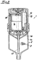
- Fig. 3 shows one in the context of the invention Process used lubricator 1 with lubricator housing 3 that from a lubricant reservoir 14 as the lower housing part and an upper housing part 15 exists.
- the electromotive is also shown Drive 4 with assigned output shaft.
- An actuating piston 16 is arranged in a rotationally fixed manner in the lubricant reservoir 14, gripped by a spindle 17 and by a Rotary movement of the spindle 17 is movable in the ejection direction.
- the upper housing part 15 can batteries 19 for Power supply included.
- the power supply of Lubricator is done from the outside.
- the lubricator for use as part of the inventive method with not shown in Fig. 3 Facilities for communication with the Central control room or is equipped with the central computer.
- electrical lines can the lubricator or connected to the circuit board be.
- the lubricator can also not shown receiving and transmitting devices for the wireless communication.
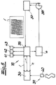
- the core of the central lubrication system is a central control unit 5, previously also referred to as the central computer, with a microcomputer 20 and a programmable logic controller Control 21.
- the central control unit 5 is in the Data exchange with the machine control 22 of the lubricating machine. Data communication is through Input signal lines 23 indicated.
- the central control unit 5 is also in data exchange with the control devices 18 of the lubricator 1, z. B. via a bus system 24.
- the central control unit 5 also has a power supply unit 25 preparation of the supply voltage for the lubricator 1, an input module 26 with inputs for sensors on the device to be lubricated, an interface 27 for download and maintenance, a control panel 28 with display, an output module 29 with outputs for the to the control devices 18 the lubricator 1 leading bus system and (optionally) has an interface 30 for remote maintenance.
- the central control device 5 is via output devices 31 for output signals with the control devices 18 of the lubricator 1 connected.
- the output devices 31 include according to that shown in FIG. 4 Block diagram of a voltage conditioning 32 for the external energy supply of the lubricator 1, a level converter 33 and devices 34 for a Signal processing.
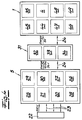
- the control device 18 is on a Inside the housing, preferably above the electromotive Drive arranged board housed and has a microcontroller as essential components 35, a data memory 36 and a motion sensor 37 for the direct or indirect recording of the Rotational movement of the output shaft.
- the Motion sensor 37 shown as a light barrier with one driven by the electric motor drive 4 Signal disk 38 cooperates.
- the microcontroller 35 is via interfaces with the motion sensor 37 and the Electromechanical drive 4 connected and is in Data exchange with the data store 36.
- the data store 36 retains its memory content regardless of the Power supply for the microcontroller 35.
- the memory content can be read and overwritten.
- the data storage 36 is also a switching device 39 with a reset switch 40 assigned to delete the data storage.
- the microcontroller 35 starts the electromotive Drive 4 based on one of the central control unit 5 emitted control pulse or in from the control device predetermined intervals.
- the number of from the motion sensor 37 signals are emitted by the microcontroller 35 counted and with a target number stored there compared. After reaching the specified number, the Motor 4 stopped.
- the microcontroller 35 adds the Measurement signals n of the motion sensor 37 continuously to one operating value stored in the data memory 36 and there the sum as a new operating value in the data memory 36 on. In the course of data exchange, the elapsed is also Dispensing time t in the data memory 36 as the operating value can be saved.
- the electric motor drive 4 with an associated control device 18 is in the upper part 15 of the lubricator 1 arranged, which is detachable with a lubricant supply 3, the piston 16 and the spindle 17 containing Lubricant container 14 is connected.
- the Lubricant container 14 with piston 16 and spindle 17 is a disposable part.
- Selector switches are located on the input interfaces of the microcontroller for the dispensing time t and for the size V of the Lubricant container 14 connected. Using the selector switch for the dispensing time t, the intervals are between the lubrication pulses changeable. The information about the Size V of the lubricant container 14 can also in Data storage 36 are stored.
- microcontroller Signal devices 41, 42 There are various output interfaces on the microcontroller Signal devices 41, 42 connected. To include a signal device 41 for displaying a necessary change of the lubricant container, which responds when the sum of the emitted by the motion sensor 37 Signals n reached a default value. Further is a signal device 42 for displaying an interference signal connected, which responds when the frequency f of the Motion sensor 37 emitted signal sequence during the Operation of the electric motor drive 4 a predetermined Control value falls below or the time interval exceeds a limit between two signals. Finally, at an output interface of the Microcontrollers 35 signaling the operational readiness Function display 43 connected to the Engine operation and the break intervals with different optical signals. There is not just one local display of the operating status of the lubricator, but the signals 41, 42, 43 described are sent via the data communication line 24 to the Central control unit 5 reported.
- the control devices 18 of the lubricator 1 are modular.
- the basic modules are the electromotive Drive 4 with an associated motion sensor for the indirect or direct detection of spindle revolutions, a circuit board with the microcontroller 35 and an interface module 44 for data communication with the central control unit 5.
- Im Further modules are provided for an exemplary embodiment internal power supply 45, for setting the Donation time 46, for signaling the operating status 47, a memory chip 48 with the data memory and one assigned switching device with reset function for the Deletion of the data memory and a device 49 for adjusting the size of the lubricant reservoir or if necessary for an automatic size detection.
Abstract
Description
Die Erfindung betrifft ein Verfahren zur Schmierung einer Vorrichtung mit mehreren Schmierstellen. Vorrichtung meint im Rahmen der Erfindung Maschinen sowie Anordnungen mit beweglichen Maschinenelementen, z. B. Förderanlagen, Kettenantriebe und dergleichen, ebenso wie Produktionsanlagen mit einer Mehrzahl von zu schmierenden Aggregaten. Aus terminologischen Gründen werden ohne Begrenzung des Schutzumfanges im folgenden die Begriffe Vorrichtung und Maschine verwendet.The invention relates to a method for lubricating a Device with multiple lubrication points. Device means machines and arrangements within the scope of the invention movable machine elements, e.g. B. Conveyors, chain drives and the like, as well as production facilities with a plurality of units to be lubricated. Out Terminological reasons are used without limitation Scope of protection in the following the terms device and Machine used.
Bei dem aus der Praxis bekannten Verfahren wird mit einem zentralen Schmierstoffvorrat gearbeitet, von dem aus der Schmierstoff über Rohrleitungen den verschiedenen Schmierstellen der Vorrichtung zugeführt wird. Das aus der Praxis bekannte Verfahren läßt zu wünschen übrig, weil die Schmierstoffzufuhr über eine Vielzahl von Rohrleitungen verhältnismäßig aufwendig ist und eine exakte Dosierung unterschiedlicher Schmiermittelmengen an den Schmierstellen nicht gelingt. Ferner ist die mögliche Länge der Rohrleitungen im Hinblick auf eine effektive Förderung des Schmierstoffes begrenzt. Schließlich kommt es in der Praxis vor, daß verschiedene Maschinenelemente einer Maschine bzw. Komponenten einer Anlage mit unterschiedlichen Schmierstoffen geschmiert werden müssen. Im Rahmen der bekannten Maßnahmen müssen dann mehrere Zentralschmieranlagen mit entsprechenden Einrichtungen zur Steuerung der Schmierstoffabgabe vorgesehen werden. In the method known from practice, a central lubricant supply, from which the Lubricant via pipes to the various lubrication points the device is supplied. That from practice Known methods leave something to be desired, because the Lubricant supply through a variety of pipes is relatively expensive and an exact dosage different amounts of lubricant at the lubrication points not succeed. Furthermore, the possible length of the pipes with a view to effective promotion of the Limited lubricant. After all, it happens in practice different machine elements of a machine or Components of a system with different lubricants need to be lubricated. As part of the known Measures must then take several central lubrication systems appropriate devices for controlling the lubricant delivery be provided.
Demgegenüber liegt der Erfindung das technische Problem zugrunde, ein Verfahren zur Schmierung einer Vorrichtung mit mehreren Schmierstellen sowie eine Zentralschmieranlage zur Durchführung des Verfahrens anzugeben, mit dem auf einfache Weise eine funktionssichere und variable Schmierstoffzufuhr, insbes. auch bei weiter beabstandeten Schmierstellen verwirklicht werden kann.In contrast, the invention is the technical problem based on a method for lubricating a device with multiple lubrication points and a central lubrication system to perform the procedure with which to simple, reliable and variable lubricant supply, especially also with more distant Lubrication points can be realized.
Gegenstand der Erfindung und Lösung dieser Aufgabe ist ein
Verfahren zur Schmierung einer Vorrichtung mit mehreren
Schmierstellen, wobei
Die Steuereinrichtung der Schmierstoffgeber ist zweckmäßigerweise auf einer Platine im Schmierstoffgebergehäuse angeordnet und mit einem Microcontroller ausgerüstet.The control device of the lubricator is expedient on a circuit board in the lubricator housing arranged and equipped with a microcontroller.
Nach dem erfindungsgemäßen Verfahren werden mit dem Zentralrechner die Betriebszustandsdaten der geschmierten Vorrichtung, insbes. die Informationen "geschmierte Maschine eingeschaltet" oder "geschmierte Maschine ausgeschaltet", abgefragt. Es liegt auch im Rahmen der Erfindung, daß von dem Zentralrechner unterschiedliche Betriebsarten der geschmierten Vorrichtung und ähnliche Betriebszustandsdaten abgefragt werden können. Zweckmäßigerweise weist die geschmierte Vorrichtung Schalt- oder Sensorelemente zur Abfrage der Betriebszustandsdaten auf.According to the inventive method Central computer the operating status data of the lubricated Device, especially the information "lubricated Machine switched on "or" lubricated machine switched off ", queried. It is also within the scope of the invention that different operating modes from the central computer the lubricated device and similar operating condition data can be queried. Conveniently the lubricated device has switching or sensor elements to query the operating status data.
Gemäß einer bevorzugten Ausführung des erfindungsgemäßen Verfahrens werden Betriebszustandsdaten der Schmierstoffgeber von den Steuereinrichtungen erfaßt und dem Zentralrechner zugeführt. Folglich erfolgt ein Signalaustausch zwischen dem Zentralrechner und den Steuereinrichtungen der Schmierstoffgeber in beiden Richtungen. Es liegt im Rahmen der Erfindung, daß der Zentralrechner die Information "Schmierstoffgeber eingeschaltet" oder "Schmierstoffgeber ausgeschaltet" abfragt. Es liegt auch im Rahmen der Erfindung, daß dem Zentralrechner bei aufgebrauchtem Schmierstoffvorrat ein entsprechendes Signal über die Leerstandsanzeige des Schmierstoffgebers zugeführt wird. Ferner können dem Zentralrechner bei Betriebsstörungen eines Schmierstoffgebers entsprechende Signale zugeführt werden. According to a preferred embodiment of the invention The operating state data of the lubricators are used detected by the control devices and the central computer fed. As a result, there is a signal exchange between the central computer and the control devices of the Lubricator in both directions. It's in the frame the invention that the central computer the information "Lubricator switched on" or "Lubricator switched off ". It is also within the scope of the Invention that the central computer when used up Lubricant supply a corresponding signal on the Empty indicator of the lubricator is fed. Furthermore, the central computer in the event of malfunctions appropriate signals supplied by a lubricator become.
Nach bevorzugter Ausführung der Erfindung erfolgt die Übermittlung der Betriebszustandsdaten der geschmierten Vorrichtung und/oder die Übermittlung der Betriebszustandsdaten der Schmierstoffgeber und/oder die Übermittlung der Steuersignale von der Zentralwarte zu den Schmierstoffgebern drahtlos. Vorzugsweise wird die drahtlose Übermittlung mit elektromagnetischen Wellen, bevorzugt mit Funksignalen durchgeführt. Es liegt auch im Rahmen der Erfindung, daß die drahtlose Übermittlung mit optischen Signalen erfolgt. Nach einer anderen Ausführungsform der Erfindung werden die Betriebszustandsdaten der geschmierten Vorrichtung und/oder der Schmierstoffgeber und/oder die von der Zentralwarte ausgehenden Steuersignale mittels einer Festverdrahtung übermittelt.According to a preferred embodiment of the invention, the transmission takes place the operating status data of the lubricated device and / or the transmission of the operating status data the lubricator and / or the transmission of the Control signals from the central control room to the lubricators wireless. Wireless transmission is preferred with electromagnetic waves, preferably with radio signals carried out. It is also within the scope of the invention that the wireless transmission with optical signals he follows. According to another embodiment of the invention become the operating state data of the lubricated device and / or the lubricator and / or that of the Control center outgoing control signals by means of a Hard wiring transmitted.
Für die Funktionssteuerung der Schmierstoffgeber bieten sich verschiedene Möglichkeiten an. Gemäß einer ersten Ausführung, die sich durch einen geringen steuerungstechnischen Aufwand auszeichnet, werden die Schmierstoffgeber von einer externen Spannungsquelle mit Spannung versorgt und wird die Spannung von der Zentralwarte bzw. über den Zentralrechner eingeschaltet und ausgeschaltet. Mit der Einschaltung der Versorgungsspannung sind die Schmierstoffgeber betriebsbereit. Die Ausführungsform zeichnet sich durch den Vorteil aus, daß der Betrieb der Schmierstoffgeber nicht von der Kapazität von Batterien oder Akkumulatoren abhängt. Bei dieser ersten Ausführungsform mit externer Spannungsversorgung wird die Schmierstoffabgabe, insbes. die Schmierstoffspendezeitpunkte und die Schmierstoffspendedauer, von der im Schmierstoffgeber angeordneten Steuereinrichtung gesteuert. Die Spendezeitpunkte und die Dauer der Spendeintervalle sind fest vorgegeben.Provide for the function control of the lubricators different options. According to a first Execution, which is characterized by a low control The lubricators are characterized by effort from an external voltage source with voltage is supplied and is the voltage from the central control room or switched on and off via the central computer. When the supply voltage is switched on, the Lubricator ready for operation. The embodiment is characterized by the advantage that the operation of the Lubricator does not depend on the capacity of batteries or accumulators depends. In this first embodiment with external power supply, the lubricant delivery, especially the lubricant dispensing times and the lubricant dispensing time, from that in the lubricator arranged control device controlled. The donation times and the duration of the donation intervals are fixed given.
Das Verfahren ist problemlos, wenn die zu schmierende Vorrichtung im Dauerbetrieb arbeitet. Ist ein durchgehender Schmierbetrieb über längere Zeiträume nicht möglich, besteht die Gefahr von Fehldosierungen, da die Abgabe der Schmierimpulse nicht ausreichend mit der tatsächlichen Betriebszeit der zu schmierenden Maschine synchronisiert ist. Das Problem kann dadurch beseitigt werden, daß die Spendezeit, in der die Schmierstoffgeber betriebsbereit sind, von den Steuereinrichtungen der Schmierstoffgeber fortlaufend erfaßt und permanent abgespeichert wird. Das aufsummierte Zeitsignal beinhaltet eine Information, welche Zeit seit dem letzten Schmierimpuls vergangen ist. Damit steht gleichzeitig auch die Restzeit bis zur Auslösung der nächsten Schmierstoffabgabe fest. Nach einer Betriebsunterbrechung greift die Steuereinrichtung auf die abgespeicherten Werte zurück und löst nach Ablauf der Restzeit den nächsten Schmierimpuls aus.The procedure is straightforward if the one to be lubricated Device works in continuous operation. Is a continuous Lubrication is not possible for long periods the risk of incorrect dosing because the dispensing of the Lubrication pulses insufficient with the actual one Operating time of the machine to be lubricated synchronized is. The problem can be solved by the fact that Dispensing time in which the lubricator is ready for operation are from the control devices of the lubricators continuously recorded and saved permanently. The accumulated time signal contains information which Time has passed since the last lubrication pulse. In order to there is also the remaining time until the next lubricant delivery. After a business interruption the control device accesses the stored ones Values back and resolves after the remaining time the next lubrication pulse.
Vorzugsweise werden die Spindelumdrehungen des elektromotorischen Antriebs der Schmierstoffgeber mittelbar oder unmittelbar durch einen Bewegungssensor erfaßt und wird die Summe der Spindelumdrehungen ebenfalls in einem Datenspeicher permanent abgespeichert. Die aufsummierten Bewegungssignale des Bewegungssensors liefern eine Information über die Stellung des Kolbens bzw. den noch vorhandenen Schmiermittelvorrat. Wird eine vorgegebene Anzahl von Spindelumdrehungen erreicht, wird an den Zentralrechner ein Signal zur Leerstandanzeige abgegeben. Preferably, the spindle revolutions of the electromotive Drive the lubricator indirectly or directly detected by a motion sensor and the Sum of the spindle revolutions also in a data memory permanently saved. The summed motion signals of the motion sensor provide information about the position of the piston or the still existing Lubricant supply. If a predetermined number of Spindle revolutions reached, is sent to the central computer Signal for vacancy indication issued.
Nach einer zweiten Ausführunsform der Erfindung werden die Schmierstoffgeber von einer im Schmierstoffgebergehäuse angeordneten Spannungsquelle mit Spannung versorgt und wird die Spannungszufuhr durch ein in der Zentralwarte bzw. vom Zentralrechner erzeugtes Signal aktiviert oder deaktiviert. Der Zentralrechner gibt während der Einschaltdauer der Steuereinrichtungen potentialfrei ein Signal an die Steuereinrichtungen ab, welches als Startsignal für die Zeitmessung genutzt wird. Die Steuereinrichtungen befinden sich sozusagen im Stand-by-Betrieb. Sobald die zu schmierende Vorrichtung in Betrieb gesetzt wird, beginnt die Erfassung der Spendezeit. Die Schmierstoffabgabe, d. h. die Schmierstoffspendezeitpunkte und die Spendedauer, wird von den Steuereinrichtungen der Schmierstoffgeber gesteuert. Bei der beschriebenen Ausführung des erfindungsgemäßen Verfahrens kann mit einer drahtlosen Signalübermittlung von der Zentralwarte bzw. von dem Zentralrechner zu den Schmierstoffgebern gearbeitet werden.According to a second embodiment of the invention, the Lubricator from one in the lubricator housing arranged voltage source is supplied with voltage and is the power supply by a in the central control room or from Central computer generated signal activated or deactivated. The central computer issues the Control devices potential-free a signal to the control devices which is the start signal for the time measurement is being used. The control devices are located so to speak in stand-by mode. As soon as the to be lubricated Device is started, the detection begins the donation time. The lubricant delivery, i.e. H. the lubricant dispensing times and the duration of the donation is determined by the Control devices of the lubricators controlled. At the described execution of the method according to the invention can with a wireless signal transmission from the central control room or from the central computer to the Lubricators are worked.
Bei den beiden vorgenannten Ausführungsformen werden die Schmierstoffgeber zunächst von der Zentralwarte aus durch Einschaltung bzw. durch Aktivierung der Spannungszufuhr betriebsbereit geschaltet. Die weitere Steuerung der Schmierstoffabgabe übernimmt die Steuereinrichtung der Schmierstoffgeber. Diese gibt feste Pulslängen zur Aktivierung des elektromotorischen Antriebs und zur Festlegung einer bestimmten Schmierstoffspendedauer vor und bestimmt außerdem feste Pausenlängen für die Unterbrechungsdauer der Schmierstoffabgabe. Die Überwachung der Schmierstoffabgabe erfolgt bei beiden Ausführungen intern im Schmierstoffgeber. Vorzugsweise wird die Anzahl der Spindelumdrehungen mittelbar oder unmittelbar durch einen Bewegungssensor erfaßt. Der elektromotorische Antrieb der Schmierstoffgeber wird in den von der Steuereinrichtung vorgegebenen Intervallen in Betrieb gesetzt und nach einer vorgegebenen Anzahl der von dem Bewegungssensor detektierten Umdrehungen gestoppt.In the two aforementioned embodiments, the Lubricators first from the central control room Switching on or by activating the voltage supply switched ready for operation. The further control of the The control device of the Lubricant dispenser. This gives fixed pulse lengths for activation of the electric motor drive and fixing a certain lubricant dispensing time before and determined also fixed break lengths for the interruption of the Lubricant delivery. Monitoring lubricant delivery in both versions takes place internally in the lubricator. The number of spindle revolutions is preferred indirectly or directly by a motion sensor detected. The electric motor drive of the lubricators is specified in the control device Intervals put into operation and according to a predetermined Number of revolutions detected by the motion sensor stopped.
Bei einer dritten Ausführungsform des erfindungsgemäßen Verfahrens erfolgt die Einschaltung bzw. Aktivierung der Spannungszufuhr ebenso wie die Steuerung der Schmierstoffabgabe von der Zentralwarte bzw. dem Zentralrechner aus. Der Zentralrechner gibt den Steuereinrichtungen der Schmierstoffgeber sowohl die Pulslänge als auch die Pausenlänge vor. Bei anstehendem Signal läuft der elektromotorische Antrieb. Bei fehlendem Signal ist der elektromotorische Antrieb abgeschaltet. Die Spendemenge ist also direkt proportional zur Signallänge.In a third embodiment of the invention The process is switched on or activated Power supply as well as the control of the lubricant delivery from the central control room or the central computer. The central computer gives the control devices the Lubricators both the pulse length and the Pause length before. When the signal is present, the electromotive is running Drive. If there is no signal, the electromotive Drive switched off. So the donation amount is directly proportional to the signal length.
Bei einer vierten Ausführungsform des erfindungsgemäßen Verfahrens wird ebenfalls mit einer von der Zentralwarte ausgelösten externen Impulssteuerung gearbeitet. Von der Zentralwarte wird den Steuereinrichtungen der Schmierstoffgeber aber lediglich ein Impuls für die Aktivierung der Schmierstoffabgabe zugeführt. Die Steuereinrichtungen übernehmen die weitere Steuerung der Schmierstoffabgabe, insbes. der Schmierstoffspendedauer. Insoweit wird bei dieser Ausführungsform bei jedem von der Zentralwarte ausgegebenen Impuls eine Schmierstoffmenge abgegeben, die von der Steuereinrichtung der Schmierstoffgeber fest vorgegeben wird. Auch bei dieser Ausführung der Erfindung empfiehlt es sich, die Anzahl der Spindelumdrehungen mittelbar oder unmittelbar durch einen Bewegungssensor zu erfassen. Der elektromotorische Antrieb der Schmierstoffgeber wird aufgrund des von dem Zentralrechner abgegebenen Steuerimpulses in Betrieb gesetzt. Nach einer vorgegebenen Anzahl der von dem Bewegungssensor detektierten Umdrehungen wird der Antrieb wieder gestoppt.In a fourth embodiment of the invention Procedure is also carried out with one from the central control room triggered external pulse control worked. Of the The control center of the lubricators is the central control room but just an impulse for the activation of the Lubricant delivery supplied. The control devices take over further control of lubricant delivery, especially the lubricant dispensing time. To that extent this embodiment in each of the central control room output pulse delivered a quantity of lubricant that from the control device of the lubricator is specified. Also in this embodiment of the invention it is recommended the number of spindle revolutions indirectly or directly through a motion sensor to capture. The electric motor drive of the lubricators is given on the basis of the central computer Control pulse started up. According to a given Number of revolutions detected by the motion sensor the drive is stopped again.
Bei externen Steuerungen der Spendezeitpunkte und der Schmierstoffmengen ist der Zentralrechner bzw. die Zentralwarte zweckmäßig über einen Standardbus an die Steuereinrichtungen der Schmierstoffgeber angeschlossen. Über den Bus können auf einfache Weise eine Mehrzahl von Signalen bzw. Informationen an die Schmierstoffgeber übermittelt werden. Die Steuereinrichtungen der Schmierstoffgeber setzen die Signale bzw. Informationen in Impulse für die Schmierstoffabgabe um.With external controls of the times of donation and the Lubricant quantities are the central computer or the central control room Appropriately via a standard bus to the control devices the lubricator is connected. On the Bus can easily handle multiple signals or information to the lubricator become. The control devices of the lubricators set the signals or information in impulses for the Lubricant delivery around.
Das erfindungsgemäße Verfahren erlaubt auf einfache Weise eine flexible und variable Schmierung von Vorrichtungen sowie Anlagen mit weit auseinanderliegenden Schmierstellen. Durch die drahtlose oder über eine Drahtverbindung verwirklichte Kommunikation zwischen dem Zentralrechner und der Mehrzahl von Schmierstellen bzw. Schmierstoffgebern ist mit geringem technischen Aufwand eine funktionssichere Schmiermittelversorgung an den Schmierstellen realisierbar. Mit dem erfindungsgemäßen Verfahren kann eine Vielzahl von Schmierstoffgebern über weite Entfernungen gesteuert werden. Bei der drahtlosen Übertragung von Funksignalen zwischen Zentralwarte und Schmierstoffgebern können beispielsweise Entfernungen von 30 bis 50 m überbrückt werden. Das erfindungsgemäße Verfahren zeichnet sich durch den besonderen Vorteil aus, daß mit der zentralen Steuerung an den verschiedenen Schmierstellen unterschiedliche Schmierstoffe in verschiedenen Schmierstoffraten und zu verschiedenen Zeiten zugeführt werden können. Bei der drahtlosen Kommunikation zwischen Zentralwarte und Schmierstoffgeber ist von besonderem Vorteil, daß an sich bereits für Funkzentralverriegelungsanlagen für Kraftfahrzeuge bekannte Elektronikelemente eingesetzt werden können. Auch insoweit läßt sich das erfindungsgemäße Verfahren einfach und mit geringem Kostenaufwand realisieren.The method according to the invention allows in a simple manner flexible and variable lubrication of devices as well as systems with widely spaced lubrication points. Realized by the wireless or via a wire connection Communication between the central computer and the majority of lubrication points or lubricators a reliable function with little technical effort Lubricant supply possible at the lubrication points. A multitude of Lubricators controlled over long distances become. For wireless transmission of radio signals between the central control room and the lubricators for example, bridging distances of 30 to 50 m become. The method according to the invention is characterized by the special advantage of that with the central control different at the different lubrication points Lubricants in different lubricant rates and too can be fed at different times. In the wireless communication between central control room and Lubricator is particularly advantageous in that already for radio central locking systems for motor vehicles known electronic elements can be used. The method according to the invention can also be used in this respect easy to implement and at low cost.
Gegenstand der Erfindung ist ferner eine Zentralschmieranlage zur Durchführung des Verfahrens. Erfindungsgemäß besteht die Zentralschmieranlage aus einer zentralen Steuereinheit mit einem Mikrocomputer und einer speicherprogrammierbaren Steuerung und aus Schmierstoffgebern, die jeweils einen elektromotorischen Antrieb mit zugeordneter Steuereinrichtung, einen Schmierstoffbehälter mit Schmierstoffvorrat, eine mit dem Antrieb verbundene Spindel sowie einen von der Spindel bewegbaren Kolben aufweisen, wobei die zentrale Steuereinheit Eingangssignalleitungen für Betriebszustandssignale der Vorrichtung aufweist und über Ausgabevorrichtungen für Ausgangssignale mit den Steuereinrichtungen der Schmierstoffgeber verbunden ist. Weitere Ausgestaltungen der erfindungsgemäßen Zentralschmieranlage sind Gegenstand der nachgeordneten Ansprüche 9 bis 22.The invention also relates to a central lubrication system to carry out the procedure. According to the invention the central lubrication system consists of a central one Control unit with a microcomputer and a programmable logic controller Control and from lubricators that one electric motor drive each with an associated one Control device, a lubricant reservoir with lubricant supply, a spindle connected to the drive and have a piston movable by the spindle, wherein the central control unit input signal lines for Has operating state signals of the device and over Output devices for output signals with the control devices the lubricator is connected. Further Refinements of the central lubrication system according to the invention are the subject of subordinate claims 9 to 22.
Im folgenden wird die Erfindung anhand einer lediglich ein Ausführungsbeispiel darstellenden Zeichnung ausführlicher erläutert. Es zeigen
- Fig. 1 und 2
- das Schema des erfindungsgemäßen Verfahrens in verschiedenen Ausführungen,
- Fig. 3
- einen Schmierstoffgeber zum Einsatz im Rahmen des erfindungsgemäßen Verfahrens,
- Fig. 4
- das Blockschaltbild einer Zentralschmieranlage zur Durchführung des erfindungsgemäßen Verfahrens,
- Fig. 5
- das Blockschaltbild einer Steuerungseinrichtung der Schmierstoffgeber.
- 1 and 2
- the scheme of the method according to the invention in different versions,
- Fig. 3
- a lubricator for use in the process according to the invention,
- Fig. 4
- the block diagram of a central lubrication system for performing the method according to the invention,
- Fig. 5
- the block diagram of a control device of the lubricator.
Das erfindungsgemäße Verfahren dient zur Schmierung von
mehreren Schmierstellen einer Maschine oder Vorrichtung.
Die Schmierstellen werden durch örtlich zugeordnete
Schmierstoffgeber 1 geschmiert, wobei die Schmierstoffgeber
1 einen im Schmierstoffgebergehäuse 2 angeordneten
Schmierstoffvorrat 3 sowie einen im Schmierstoffgebergehäuse
angeordneten elektromotorischen Antrieb 4 aufweisen
(Fig. 3).The method according to the invention serves to lubricate
several lubrication points of a machine or device.
The lubrication points are assigned by locally
Lubricator 1 lubricated, the lubricator
1 arranged in the
Die Betriebszustandsdaten der zu schmierenden Maschine und
die Betriebszustandsdaten der Schmierstoffgeber werden
einem Zentralrechner 5 einer Zentralwarte 6 zugeführt. Nach
Maßgabe der von dem Zentralrechner 5 erfaßten und ausgewerteten
Betriebszustandsdaten werden die Schmierstoffgeber
1 von der Zentralwarte 6 aus gesteuert. Anstelle des
Zentralrechners 5 oder zusätzlich zum Zentralrechner kann
auch ein Laptop 7 zur Erfassung und Auswertung der
Betriebszustandsdaten sowie zur Steuerung der Schmierstoffgeber
eingesetzt werden. Es liegt auch im Rahmen der
Erfindung, hierzu eine systemprogrammierte Steuerung (SPS)
8 einzusetzen.The operating status data of the machine to be lubricated and
the operating status data of the lubricators
a
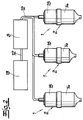
Im Ausführungsbeispiel nach Fig. 1 erfolgt die
Kommunikation zwischen der Zentralwarte 6 und den
Schmierstoffgebern 1 und/oder der Maschine drahtlos über
Funksignale. Hierzu weist die Zentralwarte 6 eine Sende- und
Empfangseinrichtung 9 auf. Es versteht sich, daß auch
die Schmierstoffgeber 1 und/oder die Maschine entsprechende
Sende- und Empfangseinrichtungen aufweisen. Im Ausführungsbeispiel
nach Fig. 1 ist mit Hilfe eines Pfeils 10
angedeutet worden, daß die Zentralwarte bzw. Zentralrechner
an einen Leitrechner 11 einer Leitzentrale, zweckmäßigerweise
über das Internet, angeschlossen ist. Die Leitzentrale
mit dem Leitrechner 11 dient vorzugsweise als
Servicezentrale, von der aus kundenspezifisch Einsätze
geplant und durchgeführt werden können.In the embodiment of FIG. 1, the
Communication between the central control room 6 and the
Lubricators 1 and / or the machine wirelessly
Radio signals. For this purpose, the central control room 6 has a transmission and
Receiving device 9. It is understood that too
the lubricator 1 and / or the machine accordingly
Have transmitting and receiving devices. In the embodiment
1 is by means of an arrow 10
has been indicated that the central control room or central computer
to a
Bei der in Fig. 2 dargestellten Ausführung des erfindungsgemäßen
Verfahrens ist der Zentralrechner 5 über ein
Bussystem 12 mit der Maschinensteuerung der zu schmierenden
Maschine 13 und mit Steuereinrichtungen der Schmierstoffgeber
1 verbunden. Die Schmierstoffgeber 1 werden auch von
der Zentralwarte aus mit Energie extern versorgt. Sie
können, was in Fig. 2 ebenfalls angedeutet ist, Schmierstoffvorratsbehälter
14 unterschiedlicher Größe aufweisen
und mit unterschiedlichen Schmierstoffen befüllt sein.In the embodiment of the invention shown in FIG. 2
The
Fig. 3 zeigt einen im Rahmen des erfindungsgemäßen
Verfahrens eingesetzten Schmierstoffgeber 1 mit Schmierstoffgebergehäuse
3, das aus einem Schmierstoffvorratsbehälter
14 als Gehäuseunterteil und einem Gehäuseoberteil
15 besteht. Dargestellt ist ferner der elektromotorische
Antrieb 4 mit zugeordneter Abtriebswelle. Ein Stellkolben
16 ist drehfest im Schmierstoffvorratsbehälter 14 angeordnet,
von einer Spindel 17 durchfaßt sowie durch eine
Drehbewegung der Spindel 17 in Ausstoßrichtung bewegbar. Im
Gehäuseoberteil 15 oberhalb des elektromotorischen Antriebs
4 ist eine Steuereinrichtung 18 auf einer Platine bzw.
Schaltplatine zur Steuerung des elektromotorischen Antriebs
4 angeordnet. Das Gehäuseoberteil 15 kann Batterien 19 zur
Spannungsversorgung enthalten. Es liegt jedoch auch im
Rahmen der Erfindung, daß die Spannungsversorgung des
Schmierstoffgebers von außen erfolgt. Es versteht sich, daß
der Schmierstoffgeber für einen Einsatz im Rahmen des
erfindungsgemäßen Verfahrens mit in Fig. 3 nicht dargestellten
Einrichtungen für die Kommunikation mit der
Zentralwarte bzw. mit dem Zentralrechner ausgerüstet ist.
Insoweit können nicht dargestellte elektrische Leitungen an
den Schmierstoffgeber bzw. an die Schaltplatine angeschlossen
sein. Der Schmierstoffgeber kann auch mit nicht
dargestellten Empfangs- und Sendeeinrichtungen für die
drahtlose Kommunikation ausgerüstet sein.Fig. 3 shows one in the context of the invention
Process used lubricator 1 with
Aufbau und Funktionsweise einer zur Durchführung des
erfindungsgemäßen Verfahrens eingerichteten Zentralschmieranlage
soll im folgenden anhand der in den Figuren 4 und 5
dargestellten Blockschaltbilder näher erläutert werden.
Kern der Zentralschmieranlage ist eine zentrale Steuereinheit
5, zuvor auch als Zentralrechner bezeichnet, mit
einem Mikrocomputer 20 und einer speicherprogrammierbaren
Steuerung 21. Die zentrale Steuereinheit 5 steht im
Datenaustausch mit der Maschinensteuerung 22 der zu
schmierenden Maschine. Die Datenkommunikation ist durch
Eingangssignalleitungen 23 angedeutet. Die zentrale Steuereinheit
5 steht ferner im Datenaustausch mit den Steuereinrichtungen
18 der Schmierstoffgeber 1, z. B. über ein Bussystem
24. Dem Blockschaltbild in Fig. 4 entnimmt man, daß
die zentrale Steuereinheit 5 ferner ein Netzteil 25 mit
einer Aufbereitung der Versorgungsspannung für die Schmierstoffgeber
1, ein Eingangsmodul 26 mit Eingängen für Sensoren
an der zu schmierenden Vorrichtung, eine Schnittstelle
27 für Download und Wartung, ein Bedienteil 28 mit Anzeige,
ein Ausgangsmodul 29 mit Ausgängen für das zu den Steuereinrichtungen
18 der Schmierstoffgeber 1 führende Bussystem
und (optional) eine Schnittstelle 30 für Fernwartung aufweist.Structure and functioning of one to carry out the
Central lubrication system set up according to the method
should be based on the in FIGS. 4 and 5
block diagrams shown are explained in more detail.
The core of the central lubrication system is a
Die zentrale Steuereinrichtung 5 ist über Ausgabevorrichtungen
31 für Ausgangssignale mit den Steuereinrichtungen
18 der Schmierstoffgeber 1 verbunden. Die Ausgabevorrichtungen
31 umfassen gemäß dem in Fig. 4 dargestellten
Blockschaltbild eine Spannungsaufbereitung 32 für
die externe Energieversorgung der Schmierstoffgeber 1,
einen Pegelwandler 33 sowie Einrichtungen 34 für eine
Signalaufbereitung.The
Aufbau und Funktionsweise der Steuereinrichtungen der
Schmierstoffgeber wird aus dem Blockschaltbild der Fig. 5
verständlich. Die Steuereinrichtung 18 ist auf einer im
Innern des Gehäuses, vorzugsweise oberhalb des elektromotorischen
Antriebs angeordneten Platine untergebracht und
weist als wesentliche Bestandteile einen Microcontroller
35, einen Datenspeicher 36 sowie einen Bewegungssensor 37
zur unmittelbaren oder mittelbaren Erfassung der
Drehbewegung der Abtriebswelle auf.Structure and functioning of the control devices of the
The lubricator is shown in the block diagram in FIG. 5
understandable. The
In dem in Fig. 5 dargestellten Blockschaltbild ist der
Bewegungssensor 37 als Lichtschranke dargestellt, die mit
einer von dem elektromotorischen Antrieb 4 angetriebenen
Signalscheibe 38 zusammenwirkt. Der Microcontroller 35 ist
über Schnittstellen mit dem Bewegungssensor 37 und dem
elektromechanischen Antrieb 4 verbunden und steht im
Datenaustausch mit dem Datenspeicher 36. Der Datenspeicher
36 behält seinen Speicherinhalt unabhängig von der
Stromversorgung des Microcontrollers 35. Der Speicherinhalt
ist les- und überschreibbar. Dem Datenspeicher 36 ist
ferner eine Schalteinrichtung 39 mit einem Reset-Schalter
40 zur Löschung des Datenspeichers zugeordnet.In the block diagram shown in Fig. 5 is the
Der Microcontroller 35 startet den elektromotorischen
Antrieb 4 aufgrund eines von der zentralen Steuereinheit 5
abgegebenen Steuerimpulses oder in von der Steuereinrichtung
vorgegebenen Intervallen. Die Anzahl der vom Bewegungssensor
37 abgegebenen Signale wird vom Microcontroller
35 gezählt und mit einer dort abgelegten Sollzahl
verglichen. Nach Erreichen der vorgegebenen Zahl wird der
Motor 4 gestoppt. Der Microcontroller 35 addiert die
Meßsignale n des Bewegungssensors 37 fortlaufend zu einem
im Datenspeicher 36 abgespeicherten Betriebswert und gibt
die Summe als neuen Betriebswert in den Datenspeicher 36
ein. Im Zuge des Datenaustauschs ist ferner die verstrichene
Spendezeit t im Datenspeicher 36 als Betriebswert
abspeicherbar.The
Der elektromotorische Antrieb 4 mit zugeordneter Steuereinrichtung
18 ist im Gehärnseoberteil 15 des Schmierstoffgebers
1 angeordnet, welches lösbar mit einem den Schmierstoffvorrat
3, den Kolben 16 und die Spindel 17 enthaltenden
Schmierstoffbehälter 14 verbunden ist. Der
Schmierstoffbehälter 14 mit Kolben 16 und Spindel 17 ist
ein Wegwerfteil. Beim Anschluß eines fabrikneuen, noch den
gesamten Schmierstoffvorrat 3 enthaltenden Schmierstoffbehälters
14 tritt der Reset-Schalter 40 mit dem Kolben 16
in Wechselwirkung und löst die Löschung des Datenspeichers
36 aus.The
An Eingabeschnittstellen des Microcontrollers sind Wahlschalter
für die Spendezeit t sowie für die Größe V des
Schmierstoffbehälters 14 angeschlossen. Mittels des Wahlschalters
für die Spendezeit t sind die Intervalle zwischen
den Schmierimpulsen veränderbar. Die Information über die
Größe V des Schmierstoffbehälters 14 kann ebenfalls im
Datenspeicher 36 abgelegt werden.Selector switches are located on the input interfaces of the microcontroller
for the dispensing time t and for the size V of the
An Ausgabeschnittstellen des Microcontrollers sind verschiedene
Signaleinrichtungen 41, 42 angeschlossen. Dazu
gehören eine Signaleinrichtung 41 zur Anzeige eines
erforderlichen Wechsels des Schmierstoffbehälters, welche
anspricht, wenn die Summe der vom Bewegungssensor 37 abgegebenen
Signale n einen Vorgabewert erreicht. Ferner ist
eine Signaleinrichtung 42 zur Anzeige eines Störsignals
angeschlossen, die anspricht, wenn die Frequenz f der vom
Bewegungssensor 37 abgegebenen Signalfolge während des
Betriebs des elektromotorischen Antriebs 4 einen vorgegebenen
Kontrollwert unterschreitet bzw. der zeitliche Abstand
zwischen zwei Signalen einen Grenzwert überschreitet.
Schließlich ist an einer Ausgabeschnittstelle des
Microcontrollers 35 eine die Betriebsbereitschaft signalisierende
Funktionsanzeige 43 angeschlossen, die den
Motorbetrieb und die Pausenintervalle mit unterschiedlichen
optischen Signalen anzeigt. Es erfolgt nicht nur eine
lokale Anzeige des Betriebszustandes des Schmierstoffgebers,
sondern die beschriebenen Signale 41, 42, 43
werden über die Datenkommunikationsleitung 24 an die
zentrale Steuereinheit 5 weitergemeldet.There are various output interfaces on the
Die Steuereinrichtungen 18 der Schmierstoffgeber 1 sind
modular aufgebaut. Grundmodule sind der elektromotorische
Antrieb 4 mit einem zugeordneten Bewegungssensor für die
mittelbare oder unmittelbare Erfassung der Spindelumdrehungen,
eine Schaltplatine mit dem Microcontroller 35
sowie ein Schnittstellenbaustein 44 für die Datenkommunikation
mit der zentralen Steuereinheit 5. Im
Ausführungsbeispiel sind weitere Module vorgesehen für eine
interne Spannungsversorgung 45, für die Einstellung der
Spendezeit 46, für die Signalisierung des Betriebszustandes
47, ein Speicherbaustein 48 mit dem Datenspeicher und einer
zugeordneten Schalteinrichtung mit Reset-Funktion für die
Löschung des Datenspeichers sowie eine Einrichtung 49 für
die Einstellung der Größe des Schmierstoffbehälters oder
ggf. für eine automatische Größenerkennung.The
Claims (22)
Priority Applications (4)
| Application Number | Priority Date | Filing Date | Title |
|---|---|---|---|
| JP10363343A JPH11287395A (en) | 1997-12-23 | 1998-12-21 | Lubricant supplying method for device having many place to be lubricated and centralized lubricating equipment for executing method |
| US09/218,410 US6125969A (en) | 1997-12-23 | 1998-12-22 | Method of and apparatus for lubricating an apparatus having a number of lubricant locations |
| CA002256150A CA2256150A1 (en) | 1997-12-23 | 1998-12-22 | Method of and apparatus for lubricating an apparatus having a number of lubricant locations |
| AU98169/98A AU739188B2 (en) | 1997-12-23 | 1998-12-23 | Method to lubricate a device with several lubrication points and a central lubricating equipment to carry out the method |
Applications Claiming Priority (2)
| Application Number | Priority Date | Filing Date | Title |
|---|---|---|---|
| DE19757546A DE19757546A1 (en) | 1997-12-23 | 1997-12-23 | Method for the central control and / or regulation of the lubrication of at least one machine |
| DE19757546 | 1997-12-23 |
Publications (2)
| Publication Number | Publication Date |
|---|---|
| EP0926426A1 true EP0926426A1 (en) | 1999-06-30 |
| EP0926426B1 EP0926426B1 (en) | 2003-04-02 |
Family
ID=7853193
Family Applications (1)
| Application Number | Title | Priority Date | Filing Date |
|---|---|---|---|
| EP98119208A Expired - Lifetime EP0926426B1 (en) | 1997-12-23 | 1998-10-12 | Method of lubrication of a device with a plurality of lubrication points and central lubrication system for carrying out said method |
Country Status (5)
| Country | Link |
|---|---|
| EP (1) | EP0926426B1 (en) |
| AT (1) | ATE236375T1 (en) |
| DE (2) | DE19757546A1 (en) |
| ES (1) | ES2193460T3 (en) |
| PT (1) | PT926426E (en) |
Cited By (8)
| Publication number | Priority date | Publication date | Assignee | Title |
|---|---|---|---|---|
| EP0994289A1 (en) * | 1998-10-12 | 2000-04-19 | Perma-Tec GmbH & Co. KG | Lubricant dispenser |
| WO2000036331A1 (en) * | 1998-12-13 | 2000-06-22 | Brückner Maschinenbau GmbH | Method for lubricating transport systems or parts thereof, the use of a lubricating device for carrying out the method, and an appropriate transport system with a corresponding lubricating device |
| WO2001002770A1 (en) * | 1999-07-02 | 2001-01-11 | Assalub Ab | Method in and device for the manual lubrication of a plurality of lubrication points |
| EP1291745A2 (en) * | 2001-09-07 | 2003-03-12 | Siemens Energy & Automation, Inc. | Programmable controller with RF wireless interface |
| BE1020552A5 (en) * | 2012-03-13 | 2013-12-03 | Cockerill Maintenance & Ingenierie Sa | DEVICE AND METHOD FOR CONTROLLING AND VALIDING MANUAL LUBRICATION. |
| US9441613B2 (en) | 2011-08-30 | 2016-09-13 | Stephania Holdings Inc. | Methods of controlling a lubricator apparatus, methods of communication, and apparatuses and systems |
| US10071756B2 (en) | 2012-04-27 | 2018-09-11 | Igralub North America, Llc | System and method for fleet wheel-rail lubrication and noise management |
| EP3483493A1 (en) * | 2017-11-10 | 2019-05-15 | Eugen Woerner GmbH & Co. KG | Lubricating installation with a communication network between main unit and at least one attachment |
Families Citing this family (3)
| Publication number | Priority date | Publication date | Assignee | Title |
|---|---|---|---|---|
| DE102004039719A1 (en) * | 2004-08-17 | 2006-02-23 | Adam Opel Ag | Pointer instrument for motor vehicle has rotation plane behind plane containing panel with tubular opening arranged so each position of pointer can be seen to read off display value, pointer hub covered by region of panel |
| DE102007033539A1 (en) | 2007-07-19 | 2009-01-22 | Perma-Tec Gmbh & Co. Kg | Multi-point lubrication, employs system of centrally-controlled, distributed lubricators containing gas generators, with delivery determined by current supplied |
| DE102017125307A1 (en) * | 2017-10-27 | 2019-05-02 | Baier & Köppel GmbH & Co. KG | Method of controlling a centralized lubrication system, computer readable storage medium, centralized lubrication system and system |
Citations (8)
| Publication number | Priority date | Publication date | Assignee | Title |
|---|---|---|---|---|
| US4368803A (en) * | 1980-08-07 | 1983-01-18 | Madison-Kipp Corporation | Apparatus for dispensing fluid onto a moving mechanical system |
| EP0374958A2 (en) * | 1988-12-23 | 1990-06-27 | Hitachi, Ltd. | Apparatus for supplying lubricant |
| EP0489603A2 (en) * | 1990-12-06 | 1992-06-10 | McNEIL (OHIO) CORPORATION | Apparatus for controlling and monitoring a lubricating system |
| EP0498242A2 (en) * | 1991-02-08 | 1992-08-12 | DROPSA S.p.A. | System for distributing lubricant to several users via remotely controlled distributors connected to the same lubricant delivery or distribution line |
| US5271528A (en) * | 1992-10-12 | 1993-12-21 | Hornche Trading Co., Ltd. | Automatic grease dispenser |
| EP0704654A1 (en) * | 1994-09-30 | 1996-04-03 | ORLITZKY, Anton | Auger-driven automatic lubricator |
| DE29715808U1 (en) * | 1997-09-03 | 1997-11-06 | Satzinger Gmbh & Co | Lubricant dispenser |
| EP0854314A2 (en) * | 1993-03-18 | 1998-07-22 | B a r m a g AG | Method and device for supplying a lubricant to an antifriction bearing |
-
1997
- 1997-12-23 DE DE19757546A patent/DE19757546A1/en not_active Withdrawn
-
1998
- 1998-10-12 PT PT98119208T patent/PT926426E/en unknown
- 1998-10-12 DE DE59807731T patent/DE59807731D1/en not_active Expired - Lifetime
- 1998-10-12 AT AT98119208T patent/ATE236375T1/en not_active IP Right Cessation
- 1998-10-12 EP EP98119208A patent/EP0926426B1/en not_active Expired - Lifetime
- 1998-10-12 ES ES98119208T patent/ES2193460T3/en not_active Expired - Lifetime
Patent Citations (8)
| Publication number | Priority date | Publication date | Assignee | Title |
|---|---|---|---|---|
| US4368803A (en) * | 1980-08-07 | 1983-01-18 | Madison-Kipp Corporation | Apparatus for dispensing fluid onto a moving mechanical system |
| EP0374958A2 (en) * | 1988-12-23 | 1990-06-27 | Hitachi, Ltd. | Apparatus for supplying lubricant |
| EP0489603A2 (en) * | 1990-12-06 | 1992-06-10 | McNEIL (OHIO) CORPORATION | Apparatus for controlling and monitoring a lubricating system |
| EP0498242A2 (en) * | 1991-02-08 | 1992-08-12 | DROPSA S.p.A. | System for distributing lubricant to several users via remotely controlled distributors connected to the same lubricant delivery or distribution line |
| US5271528A (en) * | 1992-10-12 | 1993-12-21 | Hornche Trading Co., Ltd. | Automatic grease dispenser |
| EP0854314A2 (en) * | 1993-03-18 | 1998-07-22 | B a r m a g AG | Method and device for supplying a lubricant to an antifriction bearing |
| EP0704654A1 (en) * | 1994-09-30 | 1996-04-03 | ORLITZKY, Anton | Auger-driven automatic lubricator |
| DE29715808U1 (en) * | 1997-09-03 | 1997-11-06 | Satzinger Gmbh & Co | Lubricant dispenser |
Cited By (12)
| Publication number | Priority date | Publication date | Assignee | Title |
|---|---|---|---|---|
| EP0994289A1 (en) * | 1998-10-12 | 2000-04-19 | Perma-Tec GmbH & Co. KG | Lubricant dispenser |
| WO2000036331A1 (en) * | 1998-12-13 | 2000-06-22 | Brückner Maschinenbau GmbH | Method for lubricating transport systems or parts thereof, the use of a lubricating device for carrying out the method, and an appropriate transport system with a corresponding lubricating device |
| WO2001002770A1 (en) * | 1999-07-02 | 2001-01-11 | Assalub Ab | Method in and device for the manual lubrication of a plurality of lubrication points |
| US6997286B1 (en) | 1999-07-02 | 2006-02-14 | Assalub Ab | Method in and device for the manual lubrication of a plurality of lubrication points |
| EP1291745A2 (en) * | 2001-09-07 | 2003-03-12 | Siemens Energy & Automation, Inc. | Programmable controller with RF wireless interface |
| EP1291745A3 (en) * | 2001-09-07 | 2004-03-24 | Siemens Energy & Automation, Inc. | Programmable controller with RF wireless interface |
| US6993298B2 (en) | 2001-09-07 | 2006-01-31 | Siemens Energy & Automation, Inc. | Programmable controller with RF wireless interface |
| EP1764665A1 (en) * | 2001-09-07 | 2007-03-21 | Siemens Energy & Automation, Inc. | Programmable controller with RF wireless interface |
| US9441613B2 (en) | 2011-08-30 | 2016-09-13 | Stephania Holdings Inc. | Methods of controlling a lubricator apparatus, methods of communication, and apparatuses and systems |
| BE1020552A5 (en) * | 2012-03-13 | 2013-12-03 | Cockerill Maintenance & Ingenierie Sa | DEVICE AND METHOD FOR CONTROLLING AND VALIDING MANUAL LUBRICATION. |
| US10071756B2 (en) | 2012-04-27 | 2018-09-11 | Igralub North America, Llc | System and method for fleet wheel-rail lubrication and noise management |
| EP3483493A1 (en) * | 2017-11-10 | 2019-05-15 | Eugen Woerner GmbH & Co. KG | Lubricating installation with a communication network between main unit and at least one attachment |
Also Published As
| Publication number | Publication date |
|---|---|
| ES2193460T3 (en) | 2003-11-01 |
| PT926426E (en) | 2003-08-29 |
| DE59807731D1 (en) | 2003-05-08 |
| EP0926426B1 (en) | 2003-04-02 |
| ATE236375T1 (en) | 2003-04-15 |
| DE19757546A1 (en) | 1999-07-01 |
Similar Documents
| Publication | Publication Date | Title |
|---|---|---|
| EP0994289B1 (en) | Lubricant dispenser | |
| DE4422407C2 (en) | Lubricant dispenser | |
| EP0926426B1 (en) | Method of lubrication of a device with a plurality of lubrication points and central lubrication system for carrying out said method | |
| DE60201646T2 (en) | Device for conveying a liquid | |
| EP1135645B1 (en) | Device for lubricating a rolling bearing | |
| EP0211212A2 (en) | Process and device for the determination and evaluation of machine parameters | |
| DE102017200481A1 (en) | Lubricant distribution system and method for its operation | |
| DE2823558C2 (en) | Device for monitoring complex machines such as compressor systems | |
| EP0749934A2 (en) | Method and apparatus for the determination of the dynamic stresses in parts, equipments and machines | |
| DE3232416A1 (en) | Data acquisition system for vehicles | |
| EP0102080B2 (en) | Oil quantity conditioning device in drive units | |
| DE3630327A1 (en) | CENTRAL LUBRICATION SYSTEM FOR VEHICLES | |
| EP1881204A1 (en) | Cylinder service module | |
| DE102015210716B4 (en) | Position sensor and method for operating a position sensor | |
| EP0026869B1 (en) | Device for the surveillance of the maintenance of an installation | |
| DE102017109403A1 (en) | Method and device for absolute position determination of a rotating about a rotation axis component of an actuator, in particular a clutch actuator | |
| DE3150313C2 (en) | Arrangement for determining and reporting the position of a number of switches and for monitoring the connection line | |
| DE102007033539A1 (en) | Multi-point lubrication, employs system of centrally-controlled, distributed lubricators containing gas generators, with delivery determined by current supplied | |
| EP0870728A1 (en) | Apparatus for distributing liquid fuel | |
| WO1981003233A1 (en) | Control device | |
| EP0126262A1 (en) | Device for the operation and monitoring of a dosage apparatus | |
| EP0353584B1 (en) | Machine tool or robot system with an absolute cyclic position measuring device | |
| DE102018109121A1 (en) | transmission | |
| DE2620113C3 (en) | Tariff device for the continuous recording and display of a value of the electrical consumption averaged over constant time intervals | |
| CH636969A5 (en) | Tariff device connected to an electricity meter and having a number of counting devices |
Legal Events
| Date | Code | Title | Description |
|---|---|---|---|
| PUAI | Public reference made under article 153(3) epc to a published international application that has entered the european phase |
Free format text: ORIGINAL CODE: 0009012 |
|
| AK | Designated contracting states |
Kind code of ref document: A1 Designated state(s): AT BE CH CY DE DK ES FI FR GB GR IE IT LI LU MC NL PT SE |
|
| AX | Request for extension of the european patent |
Free format text: AL;LT;LV;MK;RO;SI |
|
| RAP1 | Party data changed (applicant data changed or rights of an application transferred) |
Owner name: PERMA-TEC GMBH & CO. KG |
|
| 17P | Request for examination filed |
Effective date: 19990709 |
|
| AKX | Designation fees paid |
Free format text: AT BE CH CY DE DK ES FI FR GB GR IE IT LI LU MC NL PT SE |
|
| GRAH | Despatch of communication of intention to grant a patent |
Free format text: ORIGINAL CODE: EPIDOS IGRA |
|
| GRAH | Despatch of communication of intention to grant a patent |
Free format text: ORIGINAL CODE: EPIDOS IGRA |
|
| GRAA | (expected) grant |
Free format text: ORIGINAL CODE: 0009210 |
|
| AK | Designated contracting states |
Designated state(s): AT BE CH CY DE DK ES FI FR GB GR IE IT LI LU MC NL PT SE |
|
| PG25 | Lapsed in a contracting state [announced via postgrant information from national office to epo] |
Ref country code: NL Free format text: LAPSE BECAUSE OF FAILURE TO SUBMIT A TRANSLATION OF THE DESCRIPTION OR TO PAY THE FEE WITHIN THE PRESCRIBED TIME-LIMIT Effective date: 20030402 Ref country code: IE Free format text: LAPSE BECAUSE OF NON-PAYMENT OF DUE FEES Effective date: 20030402 |
|
| REG | Reference to a national code |
Ref country code: GB Ref legal event code: FG4D Free format text: NOT ENGLISH |
|
| REG | Reference to a national code |
Ref country code: CH Ref legal event code: EP |
|
| REG | Reference to a national code |
Ref country code: IE Ref legal event code: FG4D Free format text: GERMAN |
|
| REF | Corresponds to: |
Ref document number: 59807731 Country of ref document: DE Date of ref document: 20030508 Kind code of ref document: P |
|
| GBT | Gb: translation of ep patent filed (gb section 77(6)(a)/1977) |
Effective date: 20030520 |
|
| PG25 | Lapsed in a contracting state [announced via postgrant information from national office to epo] |
Ref country code: SE Free format text: LAPSE BECAUSE OF FAILURE TO SUBMIT A TRANSLATION OF THE DESCRIPTION OR TO PAY THE FEE WITHIN THE PRESCRIBED TIME-LIMIT Effective date: 20030702 Ref country code: GR Free format text: LAPSE BECAUSE OF FAILURE TO SUBMIT A TRANSLATION OF THE DESCRIPTION OR TO PAY THE FEE WITHIN THE PRESCRIBED TIME-LIMIT Effective date: 20030702 Ref country code: DK Free format text: LAPSE BECAUSE OF FAILURE TO SUBMIT A TRANSLATION OF THE DESCRIPTION OR TO PAY THE FEE WITHIN THE PRESCRIBED TIME-LIMIT Effective date: 20030702 |
|
| NLV1 | Nl: lapsed or annulled due to failure to fulfill the requirements of art. 29p and 29m of the patents act | ||
| PG25 | Lapsed in a contracting state [announced via postgrant information from national office to epo] |
Ref country code: LU Free format text: LAPSE BECAUSE OF NON-PAYMENT OF DUE FEES Effective date: 20031012 Ref country code: CY Free format text: LAPSE BECAUSE OF FAILURE TO SUBMIT A TRANSLATION OF THE DESCRIPTION OR TO PAY THE FEE WITHIN THE PRESCRIBED TIME-LIMIT Effective date: 20031012 Ref country code: AT Free format text: LAPSE BECAUSE OF NON-PAYMENT OF DUE FEES Effective date: 20031012 |
|
| PG25 | Lapsed in a contracting state [announced via postgrant information from national office to epo] |
Ref country code: MC Free format text: LAPSE BECAUSE OF NON-PAYMENT OF DUE FEES Effective date: 20031031 Ref country code: LI Free format text: LAPSE BECAUSE OF NON-PAYMENT OF DUE FEES Effective date: 20031031 Ref country code: CH Free format text: LAPSE BECAUSE OF NON-PAYMENT OF DUE FEES Effective date: 20031031 Ref country code: BE Free format text: LAPSE BECAUSE OF NON-PAYMENT OF DUE FEES Effective date: 20031031 |
|
| REG | Reference to a national code |
Ref country code: ES Ref legal event code: FG2A Ref document number: 2193460 Country of ref document: ES Kind code of ref document: T3 |
|
| REG | Reference to a national code |
Ref country code: IE Ref legal event code: FD4D Ref document number: 0926426E Country of ref document: IE |
|
| ET | Fr: translation filed | ||
| PLBE | No opposition filed within time limit |
Free format text: ORIGINAL CODE: 0009261 |
|
| STAA | Information on the status of an ep patent application or granted ep patent |
Free format text: STATUS: NO OPPOSITION FILED WITHIN TIME LIMIT |
|
| 26N | No opposition filed |
Effective date: 20040105 |
|
| BERE | Be: lapsed |
Owner name: *PERMA-TEC G.M.B.H. & CO. K.G. Effective date: 20031031 |
|
| REG | Reference to a national code |
Ref country code: CH Ref legal event code: PL |
|
| PGFP | Annual fee paid to national office [announced via postgrant information from national office to epo] |
Ref country code: PT Payment date: 20040920 Year of fee payment: 7 |
|
| PGFP | Annual fee paid to national office [announced via postgrant information from national office to epo] |
Ref country code: FI Payment date: 20041012 Year of fee payment: 7 |
|
| PG25 | Lapsed in a contracting state [announced via postgrant information from national office to epo] |
Ref country code: FI Free format text: LAPSE BECAUSE OF NON-PAYMENT OF DUE FEES Effective date: 20051012 |
|
| PG25 | Lapsed in a contracting state [announced via postgrant information from national office to epo] |
Ref country code: PT Free format text: LAPSE BECAUSE OF NON-PAYMENT OF DUE FEES Effective date: 20060412 |
|
| REG | Reference to a national code |
Ref country code: PT Ref legal event code: MM4A Effective date: 20060412 |
|
| PGFP | Annual fee paid to national office [announced via postgrant information from national office to epo] |
Ref country code: ES Payment date: 20081027 Year of fee payment: 11 |
|
| PGFP | Annual fee paid to national office [announced via postgrant information from national office to epo] |
Ref country code: IT Payment date: 20081025 Year of fee payment: 11 |
|
| PGFP | Annual fee paid to national office [announced via postgrant information from national office to epo] |
Ref country code: GB Payment date: 20081021 Year of fee payment: 11 |
|
| PG25 | Lapsed in a contracting state [announced via postgrant information from national office to epo] |
Ref country code: GB Free format text: LAPSE BECAUSE OF NON-PAYMENT OF DUE FEES Effective date: 20091012 |
|
| PG25 | Lapsed in a contracting state [announced via postgrant information from national office to epo] |
Ref country code: IT Free format text: LAPSE BECAUSE OF NON-PAYMENT OF DUE FEES Effective date: 20091012 |
|
| REG | Reference to a national code |
Ref country code: ES Ref legal event code: FD2A Effective date: 20110408 |
|
| PG25 | Lapsed in a contracting state [announced via postgrant information from national office to epo] |
Ref country code: ES Free format text: LAPSE BECAUSE OF NON-PAYMENT OF DUE FEES Effective date: 20110324 |
|
| PG25 | Lapsed in a contracting state [announced via postgrant information from national office to epo] |
Ref country code: ES Free format text: LAPSE BECAUSE OF NON-PAYMENT OF DUE FEES Effective date: 20091013 |
|
| PGFP | Annual fee paid to national office [announced via postgrant information from national office to epo] |
Ref country code: FR Payment date: 20121031 Year of fee payment: 15 |
|
| REG | Reference to a national code |
Ref country code: FR Ref legal event code: ST Effective date: 20140630 |
|
| PG25 | Lapsed in a contracting state [announced via postgrant information from national office to epo] |
Ref country code: FR Free format text: LAPSE BECAUSE OF NON-PAYMENT OF DUE FEES Effective date: 20131031 |
|
| PGFP | Annual fee paid to national office [announced via postgrant information from national office to epo] |
Ref country code: DE Payment date: 20170928 Year of fee payment: 20 |
|
| REG | Reference to a national code |
Ref country code: DE Ref legal event code: R071 Ref document number: 59807731 Country of ref document: DE |