EP2062831A2 - Capsule for preparing and delivering a drink by injecting a pressurized fluid into the capsule - Google Patents
Capsule for preparing and delivering a drink by injecting a pressurized fluid into the capsule Download PDFInfo
- Publication number
- EP2062831A2 EP2062831A2 EP09151919A EP09151919A EP2062831A2 EP 2062831 A2 EP2062831 A2 EP 2062831A2 EP 09151919 A EP09151919 A EP 09151919A EP 09151919 A EP09151919 A EP 09151919A EP 2062831 A2 EP2062831 A2 EP 2062831A2
- Authority
- EP
- European Patent Office
- Prior art keywords
- capsule
- fluid
- substance
- jet
- chamber
- Prior art date
- Legal status (The legal status is an assumption and is not a legal conclusion. Google has not performed a legal analysis and makes no representation as to the accuracy of the status listed.)
- Granted
Links
- 239000002775 capsule Substances 0.000 title claims abstract description 198
- 239000012530 fluid Substances 0.000 title claims abstract description 119
- 239000000126 substance Substances 0.000 claims abstract description 141
- 238000002347 injection Methods 0.000 claims abstract description 102
- 239000007924 injection Substances 0.000 claims abstract description 102
- 235000013305 food Nutrition 0.000 claims abstract description 31
- 239000007788 liquid Substances 0.000 claims abstract description 20
- 230000002829 reductive effect Effects 0.000 claims abstract description 7
- 239000012528 membrane Substances 0.000 claims description 37
- 239000000463 material Substances 0.000 claims description 19
- 235000016213 coffee Nutrition 0.000 claims description 18
- 235000013353 coffee beverage Nutrition 0.000 claims description 18
- 230000000694 effects Effects 0.000 claims description 12
- 238000002156 mixing Methods 0.000 claims description 10
- 239000011324 bead Substances 0.000 claims description 4
- 239000008187 granular material Substances 0.000 claims description 3
- 230000000452 restraining effect Effects 0.000 claims description 3
- 241001122767 Theaceae Species 0.000 claims 1
- 238000000605 extraction Methods 0.000 abstract description 12
- 238000009826 distribution Methods 0.000 abstract description 9
- 230000006872 improvement Effects 0.000 abstract description 2
- 238000003466 welding Methods 0.000 description 50
- 239000010410 layer Substances 0.000 description 29
- XLYOFNOQVPJJNP-UHFFFAOYSA-N water Substances O XLYOFNOQVPJJNP-UHFFFAOYSA-N 0.000 description 13
- 239000004033 plastic Substances 0.000 description 12
- 229920003023 plastic Polymers 0.000 description 12
- 239000004743 Polypropylene Substances 0.000 description 11
- -1 polypropylene Polymers 0.000 description 7
- 229920001155 polypropylene Polymers 0.000 description 7
- 239000000047 product Substances 0.000 description 7
- 230000008901 benefit Effects 0.000 description 6
- 238000004519 manufacturing process Methods 0.000 description 5
- 239000002245 particle Substances 0.000 description 5
- 238000003756 stirring Methods 0.000 description 5
- 244000269722 Thea sinensis Species 0.000 description 4
- 230000006835 compression Effects 0.000 description 4
- 238000007906 compression Methods 0.000 description 4
- 238000010438 heat treatment Methods 0.000 description 4
- 230000000977 initiatory effect Effects 0.000 description 4
- 238000002844 melting Methods 0.000 description 4
- 230000008018 melting Effects 0.000 description 4
- 238000000034 method Methods 0.000 description 4
- 239000011148 porous material Substances 0.000 description 4
- 239000007787 solid Substances 0.000 description 4
- 229920000742 Cotton Polymers 0.000 description 3
- 244000299461 Theobroma cacao Species 0.000 description 3
- 239000012141 concentrate Substances 0.000 description 3
- 238000011049 filling Methods 0.000 description 3
- 239000002184 metal Substances 0.000 description 3
- 229910052751 metal Inorganic materials 0.000 description 3
- 235000013336 milk Nutrition 0.000 description 3
- 239000008267 milk Substances 0.000 description 3
- 210000004080 milk Anatomy 0.000 description 3
- 230000000284 resting effect Effects 0.000 description 3
- 230000000630 rising effect Effects 0.000 description 3
- 238000003860 storage Methods 0.000 description 3
- 238000009736 wetting Methods 0.000 description 3
- 239000004793 Polystyrene Substances 0.000 description 2
- 235000009470 Theobroma cacao Nutrition 0.000 description 2
- 229920002678 cellulose Polymers 0.000 description 2
- 239000001913 cellulose Substances 0.000 description 2
- 238000010276 construction Methods 0.000 description 2
- 238000005520 cutting process Methods 0.000 description 2
- 230000001419 dependent effect Effects 0.000 description 2
- 238000000227 grinding Methods 0.000 description 2
- 235000020278 hot chocolate Nutrition 0.000 description 2
- 230000003100 immobilizing effect Effects 0.000 description 2
- 235000021539 instant coffee Nutrition 0.000 description 2
- 230000000670 limiting effect Effects 0.000 description 2
- 229920000642 polymer Polymers 0.000 description 2
- 229920000098 polyolefin Polymers 0.000 description 2
- 229920002223 polystyrene Polymers 0.000 description 2
- 239000000843 powder Substances 0.000 description 2
- 238000002360 preparation method Methods 0.000 description 2
- 238000007789 sealing Methods 0.000 description 2
- 239000000243 solution Substances 0.000 description 2
- 235000014347 soups Nutrition 0.000 description 2
- 239000004952 Polyamide Substances 0.000 description 1
- 239000004411 aluminium Substances 0.000 description 1
- 229910052782 aluminium Inorganic materials 0.000 description 1
- XAGFODPZIPBFFR-UHFFFAOYSA-N aluminium Chemical compound [Al] XAGFODPZIPBFFR-UHFFFAOYSA-N 0.000 description 1
- 238000013459 approach Methods 0.000 description 1
- 125000003118 aryl group Chemical group 0.000 description 1
- 235000013361 beverage Nutrition 0.000 description 1
- 230000015572 biosynthetic process Effects 0.000 description 1
- 235000015116 cappuccino Nutrition 0.000 description 1
- 230000015556 catabolic process Effects 0.000 description 1
- 230000008859 change Effects 0.000 description 1
- 235000019219 chocolate Nutrition 0.000 description 1
- 230000002301 combined effect Effects 0.000 description 1
- 239000002131 composite material Substances 0.000 description 1
- 238000011437 continuous method Methods 0.000 description 1
- 238000012864 cross contamination Methods 0.000 description 1
- 238000006731 degradation reaction Methods 0.000 description 1
- 230000003111 delayed effect Effects 0.000 description 1
- 229920001971 elastomer Polymers 0.000 description 1
- 239000000806 elastomer Substances 0.000 description 1
- 238000005516 engineering process Methods 0.000 description 1
- 235000015114 espresso Nutrition 0.000 description 1
- 238000001914 filtration Methods 0.000 description 1
- 238000005189 flocculation Methods 0.000 description 1
- 230000016615 flocculation Effects 0.000 description 1
- 235000015203 fruit juice Nutrition 0.000 description 1
- 239000000499 gel Substances 0.000 description 1
- 230000006698 induction Effects 0.000 description 1
- 238000003780 insertion Methods 0.000 description 1
- 230000037431 insertion Effects 0.000 description 1
- 239000000155 melt Substances 0.000 description 1
- 239000000203 mixture Substances 0.000 description 1
- 230000004048 modification Effects 0.000 description 1
- 238000012986 modification Methods 0.000 description 1
- 239000002991 molded plastic Substances 0.000 description 1
- 235000016709 nutrition Nutrition 0.000 description 1
- 238000004806 packaging method and process Methods 0.000 description 1
- 229920002647 polyamide Polymers 0.000 description 1
- 235000008476 powdered milk Nutrition 0.000 description 1
- 230000008569 process Effects 0.000 description 1
- 230000000717 retained effect Effects 0.000 description 1
- 239000000565 sealant Substances 0.000 description 1
- 239000002356 single layer Substances 0.000 description 1
- 239000002195 soluble material Substances 0.000 description 1
- 239000013589 supplement Substances 0.000 description 1
- 239000004753 textile Substances 0.000 description 1
- 238000002604 ultrasonography Methods 0.000 description 1
Images


Classifications
-
- B—PERFORMING OPERATIONS; TRANSPORTING
- B65—CONVEYING; PACKING; STORING; HANDLING THIN OR FILAMENTARY MATERIAL
- B65D—CONTAINERS FOR STORAGE OR TRANSPORT OF ARTICLES OR MATERIALS, e.g. BAGS, BARRELS, BOTTLES, BOXES, CANS, CARTONS, CRATES, DRUMS, JARS, TANKS, HOPPERS, FORWARDING CONTAINERS; ACCESSORIES, CLOSURES, OR FITTINGS THEREFOR; PACKAGING ELEMENTS; PACKAGES
- B65D85/00—Containers, packaging elements or packages, specially adapted for particular articles or materials
- B65D85/70—Containers, packaging elements or packages, specially adapted for particular articles or materials for materials not otherwise provided for
- B65D85/804—Disposable containers or packages with contents which are mixed, infused or dissolved in situ, i.e. without having been previously removed from the package
- B65D85/8043—Packages adapted to allow liquid to pass through the contents
- B65D85/8055—Means for influencing the liquid flow inside the package
-
- B—PERFORMING OPERATIONS; TRANSPORTING
- B65—CONVEYING; PACKING; STORING; HANDLING THIN OR FILAMENTARY MATERIAL
- B65D—CONTAINERS FOR STORAGE OR TRANSPORT OF ARTICLES OR MATERIALS, e.g. BAGS, BARRELS, BOTTLES, BOXES, CANS, CARTONS, CRATES, DRUMS, JARS, TANKS, HOPPERS, FORWARDING CONTAINERS; ACCESSORIES, CLOSURES, OR FITTINGS THEREFOR; PACKAGING ELEMENTS; PACKAGES
- B65D85/00—Containers, packaging elements or packages, specially adapted for particular articles or materials
- B65D85/70—Containers, packaging elements or packages, specially adapted for particular articles or materials for materials not otherwise provided for
- B65D85/804—Disposable containers or packages with contents which are mixed, infused or dissolved in situ, i.e. without having been previously removed from the package
- B65D85/8043—Packages adapted to allow liquid to pass through the contents
- B65D85/8061—Filters
Definitions
- the invention relates to a capsule configured to prepare and deliver a drink which is extracted and/or dissolved from a food substance contained in the said capsule and by injecting the pressurized fluid into the said capsule.
- capsules containing a food substance intended to be extracted under the pressure of a fluid generally water, in order to form a drink
- An example of a capsule is described in patent EP 0512468 .
- the capsule is designed to be inserted in an extraction machine.
- the closed end of the capsule comprises a tearable membrane which is opened, under the effect of the pressure of a fluid, upon contact with a membrane support equipped with reliefs in order to tear the membrane and with ducts to allow the liquid extract to pass.
- the capsule comprises a closed chamber containing the substance to be extracted or dissolved and also comprises means for opening the chamber.
- the opening of the chamber is achieved by increasing the pressure within the chamber; this pressure is increased by introducing a quantity of pressurized fluid into the chamber.
- the capsules may alternatively be permeable enclosures containing a filter or alternatively semi-permeable enclosures comprising a filter part.
- the various injection, mixing or wetting conditions may have a considerable influence over the quality of the drink produced.
- a substance to be extracted originating from a grinding, compacted into a capsule, or considering a substance to be dissolved or dispersed in a liquid, such as a soluble coffee or a milk-based substance such as a cappuccino, hot chocolate or the like
- the way in which the water circulates through the capsule has an influence over the extraction or mixing conditions and therefore on the end quality of the drink.
- a product such as coffee or chocolate needs preferably to dissolve or disperse quickly and fully, preferably producing some froth
- a soluble tea preferably needs to dissolve quickly without producing any froth.
- the dissolving or dispersing needs to be total, uniform, quick and without forming lumps or flocculation.
- the optimum wetting conditions are different.
- the product needs to be completely wetted uniformly, that is to say without creating preferred paths that the water follows through the bed of coffee.
- the way of injecting the drink may vary according to the type of substance contained in the capsule.
- co-pending European patent application No. 03019163.9 filed on 25 August 2003 relates to a method for preparing a drink by injecting a liquid through a capsule which contains a substance forming a vortex effect inside the capsule using at least one jet of pressurized water located eccentrically in the capsule.
- a jet of pressurized water causes turbulence which encourages the substance in the capsule to dissolve quickly and fully.
- the injecting of pressurized water in one or several jets in order to form turbulence is not suitable for extracting a drink from a bed of substance such as ground coffee or the like.
- the jet of water stirs up the substance and causes the fines (or small-sized particles) to settle to the bottom of the bed. The fines therefore collect near the orifices and obstruct them and considerably reduce, if not stop, the flow of the drink.
- Another problem encountered in the field of capsules relates to the reproducibility of the quality of the delivered product. This quality is particularly affected when the time taken for the drink to flow varies from one capsule to another. There are various factors that may influence this flow time including, in particular, the thickness, the flatness and/or the density of the bed of substance to be extracted. The thickness, the flatness and/or the density of the bed may vary as the capsule is transported and stored. For example, when the capsule is not kept horizontal, the bed of substance has a tendency to pile up on one side, which will form regions in which the fluid passes more quickly and other regions in which the fluid passes more slowly through the substance.
- the invention aims to provide a solution to these problems.
- the invention relates to a capsule for delivering a drink by injecting a pressurized fluid into the capsule comprising a hollow body and an injection wall attached to the body, a chamber containing a bed of at least one food substance to be extracted, means for retaining the internal pressure in the said chamber.
- the capsule comprises means configured to break the jet of fluid so as to reduce the speed of the jet of fluid injected into the capsule and distribute the fluid across the bed of substance at a reduced speed.
- food substance means any edible substance adapted for the preparation of a food, soup, beverage, medical, clinical and/or nutritional product.
- an injection space is provided, allowing an injection means in the form of at least one jet of pressurized fluid to be introduced through the injection wall.
- the fluid injection space is kept separate from the chamber by the means configured to break the jet and reduce the speed of the injected fluid jet and to distribute the distribution of fluid across the bed of substance.
- the capsule according to the invention may accept a fluid injected by means of an injection member which, in a normal capsule, would cause the substance in the capsule to be stirred up but which, by virtue of the means of breaking the jet and for distributing the flow at a reduced speed, prevents the mixing-up from happening within the substance, and in particular, does not cause the fines to settle out.
- the means for breaking the jet and for reducing the speed comprise a transversal wall which is configured to separate the injection space from the chamber containing the bed of substance in such a way as, directly or indirectly, to break the jet produced by the injection means introduced into the said injection space.
- the wall comprises welding edges which are welded against the internal surface of the hollow body in such a way as to position the said transversal wall inside the hollow body and back from the injection wall.
- a wall formed of a deformable flexible film comprises welded edges which are applied to an internal portion of the hollow body near the top surface of the food substance.
- the wall extends laterally in the form of welding edges bent up and welded against the internal surface of the body.
- the width of the welding edges is of the order of about 1 to 10 mm.
- the flexible film comprises at least one welding layer made of a material compatible with being welded to the hollow body of the capsule.
- the hollow body comprises a surface made of food grade polyolefin(s), most preferably polypropylene and the flexible film comprises a welding layer, itself made of food grade polyolefin(s), most preferably polypropylene.
- the welding layer is preferably arranged on the side of the wall facing the injection wall, set back from the edges therefrom.
- the wall of the means for breaking the injection jet may comprise one or more support layers for the welding layer.
- the support layer is not necessarily compatible with being welded to the hollow body. It may be a layer of polymer or a woven, a mat or the like, attached firmly to the welding layer.
- the wall may thus be a laminate such as PP/PET, PP/PE or PP/PA or alternatively, a monolayer such as PP or PE.
- the film may be both very fine and act as a jet breaker and splitter without rupturing.
- the thickness is less than 500 microns, preferably less than 200 microns, more preferably still, between 20 and 100 microns, for example 30-40 microns.
- the wall is equipped with a multitude of holes distributed uniformly over the surface to allow the injection liquid to pass through the bed of substance.
- the film may be applied to the body of the capsule by a continuous method after the paying out, from a roll, then the cutting of the wall and the application and welding of the edges by means of a welding die of appropriate size and shape so that it is at least partially inserted inside the body of the capsule.
- Welding can be carried out using suitable technologies such as thermal welding, ultrasonic or induction welding.
- the wall is orientated to face the said jet of fluid from the said injection means so as to break the jet directly.
- the said wall is thus positioned substantially parallel to or concave (the bulge being directed towards the closed end or bottom of the body) the injection wall.
- the expression orientated "facing" with respect to the jet is to be understood as meaning that the wall is arranged in such a way that the jet is directed in such a way as to enter into a direct impact against the wall, it being possible for the jet to arrive against this wall either with a certain angle of inclination or normal to the wall.
- the means for breaking the jet and distributing the distribution of fluid across the chamber comprise a multitude of openings passing through the said wall in such a way as to distribute the flow of fluid across the bed of substance.
- the wall serves directly or indirectly to break the jet or jets of fluid entering the capsule bound for the chamber, more specifically in the injection region provided for that purpose.
- the fluid therefore loses some of its kinetic energy as it strikes the wall directly or indirectly and then the fluid thus slowed splits into a multitude of streams through a plurality of openings so that the speed of the fluid passing through the wall is itself divided in proportion to the number of openings.
- a fluid piston is thus created that enters the chamber through the openings over practically the entire cross section of the bed of substance, and this encourages a rise in pressure in the chamber without creating an effect of turbulence in the substance.
- the fluid can therefore pass through the openings in a distributed manner at low speed, without creating turbulence, without significantly lifting the bed and without stirring up the substance itself.
- the distribution through a multitude of openings also contributes to the wetting of the substance uniformly while at the same time avoiding encouraging the creation of preferred paths through the substance.
- the openings of the perforated wall are distributed substantially uniformly across the wall so as to distribute the stream of fluid substantially uniformly across the bed of substance.
- Uniformity of the distribution of the openings is to be understood to mean a distribution of the openings over the entire surface of the wall, not necessarily symmetrically, but at least without any significant variation in the spacing between two adjacent openings.
- the holes could as well be placed in a random manner or in an organized but non-uniformed manner. For instance,the density of holes could be greater at the periphery than at the center of the capsule to favour entry of a larger amount of water in the bed from the periphery of the bed of substance toward the center line of the capsule.
- the number of openings must be enough to ensure good distribution of fluid across the substance. As a preference, the number of openings is greater than 10, preferably at least 20, more preferably still at least 50 or more.
- the shape of the openings is not critical. It may be circular, oblong, rectangular or some other shape. The size of the openings may vary. The surface area of each opening is preferably between 0.1 and 3 mm 2 .
- the wall may adopt numerous forms in order to fulfil the required functions of reducing the speed of the jet of fluid and distributing the fluid across the bed of substance.
- the perforated wall is chosen from a plastic wall with holes, a film with holes, a grating, a layer of woven or nonwoven material, a layer made of a porous material such as a layer of sponge, cotton or gauze or a combination of these.
- a layer of porous material can be inserted as a loose piece in the capsule.
- the substance to be extracted essentially occupies the entire chamber.
- the perforated wall is immobilized a distance 1 mm or less away or preferably actually in contact with the surface of the bed of substance in the chamber so as to confine the substance in the chamber. Immobilizing the wall is to be understood in the sense that the wall is arranged in the capsule in such a way that it can be neither moved nor significantly damaged upon contact with the jet of fluid entering in the injection region. Thus, the wall maintains its position and its physical integrity so that it plays its part in reducing the speed and distributing the fluid across the substance throughout injection into the capsule.
- the wall of the jet-breaking means is configured in the capsule to compress the bed of substance.
- the wall of the jet-breaking means is configured in the capsule to compress the bed of substance.
- keeping it under compression allows the bed of substance to keep its initial density substantially unchanged, in the non-hydrated state, from the time the capsule is sealed at the time of filling up to the moment when the capsule is used.
- the compression also prevents any mixing up of the substance and any possible movement of the smallest sized solid particles, particularly at the bottom of the bed.
- the means for breaking the jet of fluid and for distributing the fluid comprise a dish with a perforated wall which is inserted and immobilized in place inside the body.
- the dish shape presents certain advantages.
- the dish delimits within itself the injection region needed to accept the injection means.
- the depth of the dish is determined as a function of the injection means and of their arrangement within the intended injection space.
- the dish shape is more stable than a simple rigid sheet and is therefore better kept immobilized in the body of the capsule.
- the dish can thus be kept in contact with, or better still in compression against, the bed of substance by a membrane welded over the body of the capsule and which rests against the edges of the dish. The membrane can thus be punctured by the injection means so as to create one or more jets within the dish.
- Another advantage of the dish is its ease of insertion at the time of manufacture.
- the dish can simply be placed inside the capsule without fixing it.
- one disadvantage of the dish stems from the possibility of solid and/or liquid extract rising back up along the edges and out of the chamber. If the space intended for injection is soiled with, for example, coffee grounds, that leads to risks of the orifices in the wall itself becoming blocked, and therefore degradation of the distribution of the stream of water through the bed of substance and also a risk of the injection means becoming blocked.
- Another disadvantage stems from the industrial placement in the capsule, which requires space for several successive workstations: storage, picking, alignment and application of the dishes. The use of a dish therefore proves more expensive on an industrial scale than the use of a film, not to mention the additional cost associated with the material and manufacture of the dishes.
- jet-breaking means may include a simple sheet, flat, corrugated or otherwise, positioned in contact with the bed of substance and the cross section of which substantially corresponds to the cross section of the top surface of the bed of substance.
- the edges of the sheet are thus held in place by fixing means or simply butt against the internal walls of the body of the capsule.
- the wall is perhaps rigid so as to avoid any unwanted movement within the capsule, particularly any inclination due to transport or due to the force of the jet.
- One disadvantage is, however, the possibility of the extract rising back up along the edges because of a lack of sealing.
- the means for breaking the jet and distributing the fluid across the bed of substance comprises a flexible film equipped with orifices and welded against the edges of the body, which film has the ability to distend under the thrust of the injection fluid and press against the surface of the bed of substance.
- the distributing and jet-breaking means comprise a layer or a mass of discrete elements or at least one layer of spongy material which separates the fluid jet inlet from the surface of the bed of the substance.
- the layer or mass of discrete elements or spongy material then replaces or supplements the perforated wall and occupies substantially all or some of the "dead" volume of the chamber and/or of the injection space.
- the discrete elements may be in the form of beads, granules, sticks or the like. They are preferably made of expanded plastic.
- the plastic may be polystyrene, polypropylene or other appropriate materials.
- the density of the material used to form the discrete elements is preferably chosen to be lower than the density of the substance so as to prevent the elements, for example the beads, from settling down to the bottom of the capsule.
- the elements prevent the jet from striking the surface of the bed of substance directly and thus create a multitude of small empty spaces able to produce a flow network for the fluid entering the bed of substance.
- a spongy material can be a synthetic or natural sponge or textile such as gauze or cotton.
- the wall for breaking the jet may also be a simple flexible membrane but, in this case, it is preferable to anticipate immobilizing it in the capsule with respect to the bed of substance so as to prevent it from moving or curling up on itself, as this would render it ineffective. Immobilization may be achieved by various means such as by means of attachment to the body of the capsule or to the bed of substance itself.
- the wall forms a perforated package which holds the bed of substance in one block.
- the packaging may be made of a film material heat-shrunk around the bed, so as to keep the bed at the desired density.
- the wall is welded or bonded to the internal faces of the body.
- the capsule comprises pressure restraining means which allow the fluid inside the chamber to increase in pressure sufficiently to improve the extraction of the substance.
- These retaining means also filter the drink through at least one orifice obtained as a result of the rise in pressure in the capsule or through the construction in the capsule.
- the pressure retaining means therefore comprise at least one wall comprising at least one flow orifice or able to produce at least one flow orifice as a result of the pressure in the capsule such as by tearing, piercing, cutting of a wall for retaining the fluid in the chamber against appropriate raised means.
- the means for retaining the pressure in the capsule comprise:
- the capsule carries its own opening means, which therefore allows the opening characteristics to be tailored to suit the types of substance contained in the capsule and/or the types of drink to be produced. Another advantage is that it reduces the risk of cross-contamination when drinks of various kinds are prepared one after another.
- the raised elements are positioned on the outside of the chamber.
- the membrane then presses against the raised elements placed on the outside of the chamber.
- Such a construction has the advantage of better controlling, in particular, the opening time, the size of the punctures and the flow of the drink extract.
- the raised elements are in the chamber itself. The raised elements are pressurized by the fluid entering the chamber itself and the elements press against the puncturable membrane to create punctures and allow the drink extract to flow freely.
- the raised elements may be of different shapes, sizes and in different numbers according to the need.
- the shape, size and number of the raised elements determine the extraction characteristics, amongst other things, the rise in pressure inside the capsule, the delay to opening, the flow rate and flow time for the drink.
- the raised elements may comprise pyramids, domes, cone frustums, elongate ribs, spikes or blades.
- the raised elements are rather of non-salient shape; pyramids, cone frustums, ribs or domes will be chosen.
- salient elements such as spikes or blades are recommended.
- the number of raised elements is also dependent on the characteristics and nature of the desired drink. A higher number of raised elements has a tendency to delay the time before opening and the flow of the liquid extract. Their number may therefore vary between 1 and 200 elements.
- the pressure retaining means comprise a filter wall comprising pre-formed openings or lines or points of weakness.
- the pressure is restrained by a wall which by itself creates enough of a pressure drop to encourage a rise in pressure in the capsule and delay the flow of the drink.
- the pre-formed openings may be simple holes, pores, tortuous ducts or the like.
- the lines or points of weakness are intended to create openings once a determined pressure threshold has been exceeded, in order to allow the drink through. These may be points or lines of reduced thickness produced in the filter wall or precuts which open up and/or widen under the pressure of a fluid.
- the invention aims to avoid any significant stirring-up of the substance which could cause the fines to settle out and block these openings and impede the passage of the drink.
- the body comprises a collector for the drink and at least one pipe or passage for dispensing the drink.
- the collector comprises drink overflow means collaborating with the pipe so as to slow the stream of drink leaving the capsule.
- the invention also relates to a system for producing and delivering a plurality of drinks by injecting a pressurized fluid into capsules comprising:
- the injection device is configured to pierce the injection wall and introduce at least one injection nozzle configured to send at least one pressurized fluid jet in a direction of preference.
- a direction is preferably towards the bed of substance.
- the device is configured in such a way as to produce, in capsules without the said means for breaking this jet of fluid, turbulence in the substance which encourages rapid dissolving and/or the production of froth.
- the injection device introduces the injection nozzle eccentrically into the capsule so that it is closer to the edges of the capsule than it is to the middle of the capsule.
- Such a direction of injection further encourages the creation of swirling movements in capsules that do not have the said jet-breaking means, and this improves the dissolving of the substance and reduces the time taken to achieve this.
- the jet speed must be high enough to produce turbulence in the product inside the capsule in the absence of the jet-breaking means.
- the injection means produce at least one jet, the initial linear speed of which is at least 5 m/s, preferably at least 7 m/s.
- the invention also relates to a system for producing and delivering a plurality of drinks by injecting a pressurized fluid into capsules comprising:
- the system according to the invention therefore provides a solution in which the capsules can be tailored to a common injection device while at the same time, depending on the type of capsule, stirring up or, on the other hand, not stirring up, or at the very least significantly reducing the amount of stirring-up.
- the first capsules comprise a chamber in which the substance is confined without a head space; the second capsules comprise a chamber in which the substance occupies between 1 and 100% of the chamber.
- the first capsules the possibility of movement of particles of substance in the capsule are eliminated, whereas the second capsules have no particular constraint on the filling of their chamber, the fill rate then being dependent on factors such as the nature of the substance, the volume of drink to be produced, etc.
- the first capsules comprise a substance to be extracted, such as ground coffee or non-soluble tea; and the second capsules comprise a substance to be dissolved or dispersed in a liquid.
- the substance is wetted by the fluid at the time of extraction but the substance is kept confined in the chamber so that no significant stirring-up occurs.
- the volume of gas available may be great or small to start with (close to zero per cent) but, because of the complete dissolving of the substance combined with the flowing of the drink, a sufficient gas volume is always produced, making it possible to deliver frothy drinks.
- the jet of pressurized fluid encourages mixing in these second capsules so as to produce a great amount of stirring-up and therefore froth.
- the second capsules preferably contain soluble food gel, liquid or powder, which are substances for which good and quick dissolving or dispersing in a liquid, in order to deliver the drink in a few seconds, entails maintaining a sufficient level of turbulence in the capsule.
- the substances in the second capsules may comprise, for example, a soluble coffee concentrate, soluble tea concentrate, milk concentrate, soup or alternatively fruit juice, or a combination of these substances.
- the invention also relates to method for manufacturing a capsule for delivering a drink by injecting pressurized fluid into the capsule, the cartridge comprising a hollow body and an injection wall attached to the body, a chamber containing a bed of at least one food substance to be extracted, means for restraining the internal pressure in said chamber characterized in that a punctured element forming a jet-breaking and water distribution wall is placed transversal to the hollow body and welded to the internal side of the hollow body and at a distance from the injection wall.
- the welding operation of the punctured element is carried out after the hollow body has been filled with the food substance and before the injection wall is attached to the hollow body.
- the punctured element can be welded to the hollow body by effect of heat or ultrasound.
- the punctured element can be a membrane comprising a weldable side of lower welding initiation point or melting point than the opposite side.
- welding of the punctured element is carried out by holding the hollow body on a support die and engaging a welding die in the hollow body to position the punctured element and weld it to the internal side of the hollow body.
- the method may further comprises:
- FIGS 1 to 4 illustrate a first example of a capsule according to the principle of the invention.
- the capsule 1 comprises a body 2 in the form of a cup and an injection wall 3 which closes the open part of the cup.
- the body may be made of thermoformed plastic, for example. It comprises upper edges 20 against which the injection wall 3 rests and is welded and/or bonded.
- the injection wall 3 may advantageously be a plastic or aluminium membrane or a composite multilayer that can be punctured and is impermeable to liquids and to air.
- the body 2 comprises a chamber 4 in which the food substance to be extracted is housed.
- the food substance adopts a position in this chamber in the form of a bed of substance, of which the surfaces transverse to the passage of the fluid through the bed are delimited, on the one hand, by opening means 5 and, on the other hand, by a means 6 of breaking the injection fluid and of distributing this fluid across the chamber 4.
- the chamber is also delimited by the sides 21 of the body.
- the food substance generally contains a product to be extracted, such as ground coffee or tea. Coffee produces a fairly high percentage of fines, of the order of 5 to 30%, during the grinding process. The fines are particles of coffee the size of which is below the norm, generally below 90 microns.
- the means 6 of breaking the jet of injection fluid and of distributing this fluid in the chamber generally comprises a wall 60 able to break the jet or jets of fluid entering the capsule before the fluid reaches the substance to be extracted so as to avoid stirring this substance up.
- the means 6 for breaking the jet of injection fluid and for distributing this fluid is a perforated flexible membrane 60 comprising turned-up edges 61 welded against the internal face of the sides 21 of the body. The membrane thus forms a dish thus delimiting an injection space 7 allowing an injection device foreign to the capsule to be introduced.
- the membrane comprises a multitude of punctures or holes allowing the fluid to flow in a manner that is distributed across the bed of the substance 18 in the capsule.
- the element 6 for breaking the jet is an element in the form of a fine membrane welded against the internal wall of the body of the capsule after the said capsule has been filled with the food substance such as a dose of ground coffee, for example.
- the general steps in the method of manufacturing the capsule thus comprise:
- FIGS 2 to 4 more specifically illustrate step “b" of welding the element 6 in the capsule.
- the capsule having been filled with food substance (step a) is placed in a support die 12, the edges 20 of the body resting against bearing edges 120 of the support die.
- the element 6 is then interposed between the said support die and a welding die 13 comprising a welding die portion.
- the element 6 may thus be precut to the desired dimensions and held against the welding die by suction of air or a sucker effect or may simply be placed against the edges 20 of the body of the capsule or alternatively be held by being trapped slightly between the two die parts 12, 13.
- the welding die has a narrowed, for example truncoconical, welding portion 14 which fits against the shape of the wall of the body.
- a heating element 15 surrounds the die to supply the heat needed to the welding portion by conduction effect.
- the heating element may have passing through it or be connected to heating resistive elements (not depicted).
- Figure 3 shows the lowering of the welding die 13 into the body of the capsule in order to drive the membrane 6 back into a welding position and the actual welding of this membrane against the inside of the body.
- Welding takes place over a sufficient edge area 17 that it affords the element sufficient resistance to the fluid pressure.
- the welding is obtained by heating this edge portion until the surface of the film in contact with the internal surface of the body melts.
- the opposite surface of the film that is to say the surface in contact with the welding die, is not brought up to its melting or welding initiation point, so as to prevent the film from sticking to the die as the die is withdrawn, as this would have the effect of pulling the film off or tearing it.
- the welding initiation point refers here to the welding temperature of the material forming the sealant at which a minimum seal strength is obtained.
- Seal strength is the strength of the bond at a given welding temperature.
- the sealing is the ability of surfaces of films to form a bond or seal that is resistant to pulling apart, peeling, delaminating or otherwise failing under the effect of pressure and heat over a period of time.
- the film is therefore a laminate formed of several layers of polymers including a welding layer 600 (on the body internal wall side) made of a material with a lower melting point or welding initiation point than the external layer 601 of the film ( Figure 4 ).
- the inner welding layer is, for example, made of polypropylene when the body of the capsule is made of polypropylene; the outer layer then being made of a material such as a polyamide. If necessary, the central part of the die is cooled to prevent the film from sticking to the die, particularly as a result of melting of the layer 600, as this could then block the punctures and cause the film to stick to the die.
- the hot-welding means may be replaced by ultrasonic welding means or other appropriate means.
- the film forming the element 6 is brought in the form of a continuous sheet paid out by a roll or a plate and interposed between the jaw 12 and the die 13, then welded and cut. The welding may be done sequentially or simultaneously.
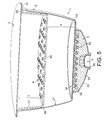
- FIGS 5 to 9 illustrate a second example of a capsule according to the principle of the invention.
- the capsule 1 comprises a body 2 in the form of a cup and an injection wall 3 which closes the open part of the cup.
- the means 6 for breaking the jet of injection fluid and distributing this fluid is a self-supporting plastic such as a rigid or semi-rigid plastic.
- the means 6 is a simple dish placed inside the body without welding.
- the injection device may be a puncturing nozzle 8 equipped with a spike 80 and with one or several orifices 81 as shown by Figure 5 .
- the injection device is thus configured to orientate one or more jets of pressurized fluid towards the inside of the space 7.
- the jet of pressurized fluid is preferably aimed towards the substance contained in the capsule, either downwards or at a certain angle of inclination (as illustrated).
- the jet is relatively powerful with a linear speed of at least 5 m/s, preferably at least 7 m/s.
- This device is configured to create turbulence, or swirling movement of fluid about the central axis of the capsule, I, or alternatively a movement directed towards this axis I.
- Such a device is particularly effective at dissolving powders or other soluble materials while generating a stirring-up of the substance within the capsule.
- the capsule according to the invention does, however, possess means for breaking this jet of fluid and therefore avoids the stirring-up of the substance in the chamber and thus allows the capsule also to be rendered suitable for receiving this type of injection means. It will therefore be understood that the capsule according to the invention suits injection means which, in principle, are designed, in the absence of the means 6 for reducing the speed of the jet and for distributing, to produce a stirring-up of the substance in the capsule as in the case of powdered coffee, cocoa and/or milk.
- the modification made to the present capsule allows these injection means to be used without the problems associated with the stirring-up of the substance because the stirring-up is eliminated by the means 6 which break the jet and by the passing of the fluid through the numerous openings provided.
- other substances such as ground roasted coffee can be extracted without the need to change the injection means.
- the dish 6 comprises a transverse or end wall 60 equipped with a multitude of holes 62 distributed across the said wall, preferably in such a way as uniformly to cover the entire surface of the said wall.
- a transverse or end wall 60 equipped with a multitude of holes 62 distributed across the said wall, preferably in such a way as uniformly to cover the entire surface of the said wall.
- the dish is inserted in the body simply by placement.
- the injection wall 3, preferably a membrane welded to the edges 20, serves to keep the dish 60 bearing either against the sides of the body along a line of bearing 64 of the dish when the body has a narrowed shape and/or the rims 65, or alternatively bearing directly against the substance, or alternatively preferably bearing both against the body and against the substance.
- the dish is thus immobilized by the resting or restings between the wall 3 and the body 2 and/or the top surface of the bed of substance (not depicted).
- the wall 60 of the dish can thus keep the substance confined and in compression in the chamber, which guarantees reproducible flow characteristics.
- the dish may advantageously be manufactured from a single piece of thermoformed or injection moulded plastic, or alternatively may be manufactured from a single piece of pressed or injected metal.
- the capsules in Figures 1 to 9 comprise pressure retaining means 5 which allow the liquid extract or drink to be released through a passage or pipe 9 when a certain pressure has been reached in the chamber.
- the opening means comprise a puncturable membrane 50 connected to internal rims 22 of the body which are situated at the lower limit of the chamber.
- the membrane may be connected by any appropriate means of sealed connection such as by welding, bonding or other equivalent means.
- the membrane collaborates for opening with a disc-shaped part 51 comprising raised elements 52 delimiting a series of ducts or spaces 53.
- FIG 10 shows an example of an opening piece comprising these raised elements.
- This piece 5A is an injection-moulded disc comprising raised elements of frustoconical shape 520 and spaces 530 for collecting the liquid extract crossing the membrane.
- rims 54 delimiting openings, passages or slots 55 to drain the drink between a collector 25 of the body and the opening piece 5A.
- Ribs may be provided under the piece to enhance the pressure withstand of the piece and make it easier to evacuate the drink towards the delivery pipe 9.
- the pipe 9 preferably comprises an overflow means in the form of an S-shaped rim, for example, which forces the stream of liquid to recentre itself, preserving the quality of the froth and thus limiting splashes.
- Figure 11 shows another example of a piece 5B used to open the membrane in which the raised elements 521 are pyramid shaped and separate ducts 522 forming a flow network over the surface of the piece.
- the rims 540 of the piece demarcate slots 550 for the passage of the drink.
- the capsule is opened in order to release the liquid extract when the pressure exerted on the membrane 50 is such that the membrane punctures at the sites of the raised elements, therefore creating a multitude of orifices in the membrane.
- the fluid can flow between the surface of the raised elements and the edges of the orifices of the membrane with a filter effect so that all the solid particles remain trapped within the chamber.
- the extract may therefore flow between the spaces 530 or ducts 522 then through the slots 55, 550, along the edges of the collector and/or of grooves (not depicted) situated under the piece as far as the pipe 9.
- Figure 12 shows another embodiment of the capsule according to the invention in which the difference compared with the previous embodiments stems from the retaining means 5 which have a filter wall 58 equipped with points or lines of weakness 580.
- the wall 58 with the injection wall 3 forms a closed enclosure.
- a support element 59 such as one comprising non-puncturing ribs, may be arranged in order to prevent the wall 58 from collapsing as a result of the pressure exerted in the chamber.
- the liquid can therefore flow through grooves or ducts 590 present in and/or under these support elements 59 and be discharged through the drink delivery pipe 9.
- Figure 13 shows another embodiment of a capsule in which the wall 581 of the pressure retaining means of the chamber 4 has pre-formed openings 582 configured to allow the fluid to pass above a certain pressure in the chamber.
- the wall is already open and creates a pressure drop that has to be overcome so that the fluid can be collected through the pipe 9.
- One disadvantage of such a capsule is that it requires overwrapping or at least a pealable seal that hermetically closes the pipe 9 so as to preserve the freshness of the substance it contains.
- Figure 14 shows an example in which the means for reducing the speed of the jet and for distributing the flow of the fluid consists of an element 66 comprising at least a layer of a woven or nonwoven material.
- a layer may be a woven, a mat, made of plastic, cellulose, cotton or some other material.
- the element may comprise other layers or webs providing the means with rigidity such as filaments, strips or metal and/or plastic ribs, layers of porous material or the like.
- the element 66 may have a disc shape as illustrated in Figure 10 or a dish shape as illustrated previously.
- the element 66 may alternatively be in the form of a disc which is placed in a support basket made of metal or plastic filaments the height of which defines the injection space 7.
- the wall of the means for breaking the jet comprises a flexible film, equipped with a multitude of orifices, secured to the body 2 and/or to the injection wall 3 and configured to distend under the effect of the injection of the fluid between its surface and the injection wall and spread the fluid out through its orifices.
- the film may advantageously be retained by its edges between in the weld line of the edge 20 of the body of the capsule and of the injection wall 3.
- the film may be a fine film (for example 100 to 600 microns thick) made of polypropylene or elastomer, for example, equipped with multiple orifices (for example between 30 and 100). When the injection nozzle is introduced through the wall 3, it pushes the film back towards the inside without puncturing it.
- the water then introduced between the wall 3 and the film allows the film to distend and therefore press against the surface of the bed of substance.
- the film can deform elastically from a smaller initial size and/or deploy if a film of a larger initial size is provided.
- the film therefore stabilizes the bed of substance and prevents a turbulence/stirring-up regime from becoming established within the chamber.
- the water flows uniformly through the orifices of the film and through the surface of the substance.
- the means for breaking the jet and distributing the fluid across the bed of substance may comprise a layer 67 which separates the entry of the jet of fluid from the surface of the bed of substance, which layer 67 comprises a plurality of macroscopic elements 670 such as beads, granules or sticks or other equivalent elements.
- These elements 670 are preferably in a material of a density lower than the density of the substance 18 contained in the capsule and/or the layer 67 has a mass per unit volume lower than the mass per unit volume of the bed of substance so that the elements remain on the surface of the bed of substance under dry conditions and under the hydraulic conditions of extraction.
- These may be elements made of expanded plastic or cellulose for example.
- the elements occupy all or some of the volume between the jet of fluid entering the capsule and the surface of the bed of substance while at the same time freeing up a network of gaps 671 between each contiguous element 670 for the passage of the fluid through the layer 67 at a speed that is reduced by comparison with the initial speed of the jet of fluid leaving the injection means.
- the elements are preferably made of food-grade material and are preferably inert under the heat, pressure and humidity conditions of extraction and under the conditions of storage in contact with the food substance.
- the size of the elements may vary and be of the order of 1 to 8 mm approximately, preferably 2.5 to 6 mm.
- These elements prevent the jet from striking the surface of the bed of substance 18 directly and thus create a multitude of small empty spaces able to produce a flow network for the fluid entering the bed of substance.
- They are preferably made of food grade plastic such as polypropylene, polystyrene or some other appropriate material.
- the invention also relates to a system for producing and delivering a plurality of drinks by injecting a pressurized fluid into capsules comprising an injection device of the type illustrated in Figure 9 or alternatively described and featured in detail in the co-pending European application EP No. 03019163.9 entitled: "Food preparation method".
- the injection device thus produces at least one jet of pressurized fluid in the said capsules.
- An assortment of first and second capsules is provided in the system, these being configured to be combined with the injection device.
- Each capsule in the assortment thus comprises a body and an injection wall, a chamber containing at least one food substance, means for retaining the internal pressure in the said chamber.
- the first capsules are of the type of those described in this application, that is to say that they comprise, in addition to the general means thus defined, means configured to break the jet of fluid injected and to split the flow as the fluid passes through the substance so as to reduce or eliminate the stirring-up of the substance in the chamber.
- the second capsules are, for their part, configured in the same general manner but without the said means 6, 60, 62 so as to encourage, unlike the said first capsules, a certain stirring-up of the substance in the chamber of the second capsules. Capsules not employing these means for breaking the jet of fluid are thus described and illustrated in detail in patent application WO 03/059778 , for example, which application is inserted here by reference.
Abstract
Description
- The invention relates to a capsule configured to prepare and deliver a drink which is extracted and/or dissolved from a food substance contained in the said capsule and by injecting the pressurized fluid into the said capsule.
- Numerous examples of capsules containing a food substance intended to be extracted under the pressure of a fluid, generally water, in order to form a drink are known. An example of a capsule is described in patent
EP 0512468 . The capsule is designed to be inserted in an extraction machine. The closed end of the capsule comprises a tearable membrane which is opened, under the effect of the pressure of a fluid, upon contact with a membrane support equipped with reliefs in order to tear the membrane and with ducts to allow the liquid extract to pass. - Another example of a capsule is described in application
WO 03/059778 A2 - The capsules may alternatively be permeable enclosures containing a filter or alternatively semi-permeable enclosures comprising a filter part. There are also capsules in existence that comprise one or more restrictions forming a jet of drink and which may or may not be associated with filtering walls.
- It is known practice to employ substances for mixing (soluble or dispersible) and to carry out extraction under pressure using the same machine so as to offer a greater variety of drinks. For example, one and the same machine can be used to prepare an "espresso" coffee when the capsule contains ground coffee or a hot chocolate when the substance contains a mixture of cocoa and powdered milk. However, it is found that filling a capsule with a substance of a different nature is not enough to obtain a drink of good quality in terms of aroma, taste and/or volume of froth for example.
- In particular, the various injection, mixing or wetting conditions may have a considerable influence over the quality of the drink produced. Whether considering a substance to be extracted, originating from a grinding, compacted into a capsule, or considering a substance to be dissolved or dispersed in a liquid, such as a soluble coffee or a milk-based substance such as a cappuccino, hot chocolate or the like, the way in which the water circulates through the capsule has an influence over the extraction or mixing conditions and therefore on the end quality of the drink. Thus, a product such as coffee or chocolate needs preferably to dissolve or disperse quickly and fully, preferably producing some froth, whereas a soluble tea preferably needs to dissolve quickly without producing any froth. The dissolving or dispersing needs to be total, uniform, quick and without forming lumps or flocculation. In the case of products to be extracted such as ground coffee, the optimum wetting conditions are different. The product needs to be completely wetted uniformly, that is to say without creating preferred paths that the water follows through the bed of coffee.
- Thus, the way of injecting the drink may vary according to the type of substance contained in the capsule. For example, co-pending European patent application No.
03019163.9 filed on 25 August 2003 - However, the injecting of pressurized water in one or several jets in order to form turbulence is not suitable for extracting a drink from a bed of substance such as ground coffee or the like. In particular, the jet of water stirs up the substance and causes the fines (or small-sized particles) to settle to the bottom of the bed. The fines therefore collect near the orifices and obstruct them and considerably reduce, if not stop, the flow of the drink.
- There is therefore a need for a capsule which is able to accept the fluid from the injection means of the water jet type but without presenting the problems associated with these means; namely without generating a mixing up of the bed and, therefore, without causing the fines to settle out and therefore without obstructing the openings through which the drink is supposed to pass.
- Another problem encountered in the field of capsules relates to the reproducibility of the quality of the delivered product. This quality is particularly affected when the time taken for the drink to flow varies from one capsule to another. There are various factors that may influence this flow time including, in particular, the thickness, the flatness and/or the density of the bed of substance to be extracted. The thickness, the flatness and/or the density of the bed may vary as the capsule is transported and stored. For example, when the capsule is not kept horizontal, the bed of substance has a tendency to pile up on one side, which will form regions in which the fluid passes more quickly and other regions in which the fluid passes more slowly through the substance.
- It is therefore important to ensure control over the thickness, the flatness and/or the density of the bed of substance to be extracted so as to guarantee good reproducibility of the extraction conditions.
- The present invention aims to provide a solution to these problems. Hence, the invention relates to a capsule for delivering a drink by injecting a pressurized fluid into the capsule comprising a hollow body and an injection wall attached to the body, a chamber containing a bed of at least one food substance to be extracted, means for retaining the internal pressure in the said chamber. According to an improvement of the invention, the capsule comprises means configured to break the jet of fluid so as to reduce the speed of the jet of fluid injected into the capsule and distribute the fluid across the bed of substance at a reduced speed.
- In the context of the invention, food substance means any edible substance adapted for the preparation of a food, soup, beverage, medical, clinical and/or nutritional product.
- In one embodiment of the invention, an injection space is provided, allowing an injection means in the form of at least one jet of pressurized fluid to be introduced through the injection wall. Thus, the fluid injection space is kept separate from the chamber by the means configured to break the jet and reduce the speed of the injected fluid jet and to distribute the distribution of fluid across the bed of substance.
- Hence, the capsule according to the invention may accept a fluid injected by means of an injection member which, in a normal capsule, would cause the substance in the capsule to be stirred up but which, by virtue of the means of breaking the jet and for distributing the flow at a reduced speed, prevents the mixing-up from happening within the substance, and in particular, does not cause the fines to settle out.
- According to one aspect of the invention, the means for breaking the jet and for reducing the speed comprise a transversal wall which is configured to separate the injection space from the chamber containing the bed of substance in such a way as, directly or indirectly, to break the jet produced by the injection means introduced into the said injection space.
- According to one embodiment of the invention, the wall comprises welding edges which are welded against the internal surface of the hollow body in such a way as to position the said transversal wall inside the hollow body and back from the injection wall.
- This particular embodiment combines several advantages:
- the jet-breaking means are close to the surface of the food substance, for example the bed of ground coffee, and this allows the bed of coffee to be held better in place;
- welding the edges of the means to the inside of the body makes it possible to prevent the liquid and/or solid extract from rising up along the edges of the body of the capsule, the bed of substance also remaining better compacted under the combined effect of the wall thus welded and the pressure of the fluid;
- the means are, by the same token, kept away from the injection wall, including along the edges, and this ensures injection by intrusive means which can be inserted into the capsule at any point, for example along the edges, without however damaging the wall of jet-breaking means, such as puncturing it for example,
- as a result, the injection wall can be made of a flexible and inexpensive material because it is not subjected to stretching or tearing caused by the injection means of the system.
- Hence, in this embodiment of the invention, it will be preferable to use a wall formed of a deformable flexible film. Such a wall comprises welded edges which are applied to an internal portion of the hollow body near the top surface of the food substance.
- The wall extends laterally in the form of welding edges bent up and welded against the internal surface of the body. The width of the welding edges is of the order of about 1 to 10 mm.
- The flexible film comprises at least one welding layer made of a material compatible with being welded to the hollow body of the capsule. In a preferred example, the hollow body comprises a surface made of food grade polyolefin(s), most preferably polypropylene and the flexible film comprises a welding layer, itself made of food grade polyolefin(s), most preferably polypropylene.
- The welding layer is preferably arranged on the side of the wall facing the injection wall, set back from the edges therefrom.
- The wall of the means for breaking the injection jet may comprise one or more support layers for the welding layer. The support layer is not necessarily compatible with being welded to the hollow body. It may be a layer of polymer or a woven, a mat or the like, attached firmly to the welding layer. The wall may thus be a laminate such as PP/PET, PP/PE or PP/PA or alternatively, a monolayer such as PP or PE.
- Surprisingly, the film may be both very fine and act as a jet breaker and splitter without rupturing. The thickness is less than 500 microns, preferably less than 200 microns, more preferably still, between 20 and 100 microns, for example 30-40 microns.
- The wall is equipped with a multitude of holes distributed uniformly over the surface to allow the injection liquid to pass through the bed of substance.
- The film may be applied to the body of the capsule by a continuous method after the paying out, from a roll, then the cutting of the wall and the application and welding of the edges by means of a welding die of appropriate size and shape so that it is at least partially inserted inside the body of the capsule.
- Welding can be carried out using suitable technologies such as thermal welding, ultrasonic or induction welding.
- In one configuration, the wall is orientated to face the said jet of fluid from the said injection means so as to break the jet directly. In one embodiment, the said wall is thus positioned substantially parallel to or concave (the bulge being directed towards the closed end or bottom of the body) the injection wall. The expression orientated "facing" with respect to the jet is to be understood as meaning that the wall is arranged in such a way that the jet is directed in such a way as to enter into a direct impact against the wall, it being possible for the jet to arrive against this wall either with a certain angle of inclination or normal to the wall.
- For preference, the means for breaking the jet and distributing the distribution of fluid across the chamber comprise a multitude of openings passing through the said wall in such a way as to distribute the flow of fluid across the bed of substance.
- Thus, the wall serves directly or indirectly to break the jet or jets of fluid entering the capsule bound for the chamber, more specifically in the injection region provided for that purpose. The fluid therefore loses some of its kinetic energy as it strikes the wall directly or indirectly and then the fluid thus slowed splits into a multitude of streams through a plurality of openings so that the speed of the fluid passing through the wall is itself divided in proportion to the number of openings. A fluid piston is thus created that enters the chamber through the openings over practically the entire cross section of the bed of substance, and this encourages a rise in pressure in the chamber without creating an effect of turbulence in the substance. The fluid can therefore pass through the openings in a distributed manner at low speed, without creating turbulence, without significantly lifting the bed and without stirring up the substance itself. The distribution through a multitude of openings also contributes to the wetting of the substance uniformly while at the same time avoiding encouraging the creation of preferred paths through the substance.
- As a preference, the openings of the perforated wall are distributed substantially uniformly across the wall so as to distribute the stream of fluid substantially uniformly across the bed of substance. Uniformity of the distribution of the openings is to be understood to mean a distribution of the openings over the entire surface of the wall, not necessarily symmetrically, but at least without any significant variation in the spacing between two adjacent openings. However, the holes could as well be placed in a random manner or in an organized but non-uniformed manner. For instance,the density of holes could be greater at the periphery than at the center of the capsule to favour entry of a larger amount of water in the bed from the periphery of the bed of substance toward the center line of the capsule.
- The number of openings must be enough to ensure good distribution of fluid across the substance. As a preference, the number of openings is greater than 10, preferably at least 20, more preferably still at least 50 or more. The shape of the openings is not critical. It may be circular, oblong, rectangular or some other shape. The size of the openings may vary. The surface area of each opening is preferably between 0.1 and 3 mm2 .
- The wall may adopt numerous forms in order to fulfil the required functions of reducing the speed of the jet of fluid and distributing the fluid across the bed of substance. In general, the perforated wall is chosen from a plastic wall with holes, a film with holes, a grating, a layer of woven or nonwoven material, a layer made of a porous material such as a layer of sponge, cotton or gauze or a combination of these. For instance, a layer of porous material can be inserted as a loose piece in the capsule.
- According to one aspect of the invention, the substance to be extracted essentially occupies the entire chamber. The perforated wall is immobilized a distance 1 mm or less away or preferably actually in contact with the surface of the bed of substance in the chamber so as to confine the substance in the chamber. Immobilizing the wall is to be understood in the sense that the wall is arranged in the capsule in such a way that it can be neither moved nor significantly damaged upon contact with the jet of fluid entering in the injection region. Thus, the wall maintains its position and its physical integrity so that it plays its part in reducing the speed and distributing the fluid across the substance throughout injection into the capsule.
- Confining the substance in the chamber makes it possible to avoid the substance being significantly stirred up during extraction and, during transport and storage, makes sure that the thickness of the bed is maintained regardless of the spatial orientation of the capsule.
- For preference even, the wall of the jet-breaking means is configured in the capsule to compress the bed of substance. Thus, keeping it under compression allows the bed of substance to keep its initial density substantially unchanged, in the non-hydrated state, from the time the capsule is sealed at the time of filling up to the moment when the capsule is used. The compression also prevents any mixing up of the substance and any possible movement of the smallest sized solid particles, particularly at the bottom of the bed.
- In one advantageous embodiment, the means for breaking the jet of fluid and for distributing the fluid comprise a dish with a perforated wall which is inserted and immobilized in place inside the body. The dish shape presents certain advantages. The dish delimits within itself the injection region needed to accept the injection means. Thus, the depth of the dish is determined as a function of the injection means and of their arrangement within the intended injection space. The dish shape is more stable than a simple rigid sheet and is therefore better kept immobilized in the body of the capsule. The dish can thus be kept in contact with, or better still in compression against, the bed of substance by a membrane welded over the body of the capsule and which rests against the edges of the dish. The membrane can thus be punctured by the injection means so as to create one or more jets within the dish. Another advantage of the dish is its ease of insertion at the time of manufacture. Thus, the dish can simply be placed inside the capsule without fixing it. However, one disadvantage of the dish stems from the possibility of solid and/or liquid extract rising back up along the edges and out of the chamber. If the space intended for injection is soiled with, for example, coffee grounds, that leads to risks of the orifices in the wall itself becoming blocked, and therefore degradation of the distribution of the stream of water through the bed of substance and also a risk of the injection means becoming blocked. Another disadvantage stems from the industrial placement in the capsule, which requires space for several successive workstations: storage, picking, alignment and application of the dishes. The use of a dish therefore proves more expensive on an industrial scale than the use of a film, not to mention the additional cost associated with the material and manufacture of the dishes.
- Other possible forms incorporating the jet-breaking means are possible without departing from the scope of the invention. These may include a simple sheet, flat, corrugated or otherwise, positioned in contact with the bed of substance and the cross section of which substantially corresponds to the cross section of the top surface of the bed of substance. The edges of the sheet are thus held in place by fixing means or simply butt against the internal walls of the body of the capsule. In this case, the wall is perhaps rigid so as to avoid any unwanted movement within the capsule, particularly any inclination due to transport or due to the force of the jet. One disadvantage is, however, the possibility of the extract rising back up along the edges because of a lack of sealing.
- In another possible form, the means for breaking the jet and distributing the fluid across the bed of substance comprises a flexible film equipped with orifices and welded against the edges of the body, which film has the ability to distend under the thrust of the injection fluid and press against the surface of the bed of substance.
- In another possible form, the distributing and jet-breaking means comprise a layer or a mass of discrete elements or at least one layer of spongy material which separates the fluid jet inlet from the surface of the bed of the substance. The layer or mass of discrete elements or spongy material then replaces or supplements the perforated wall and occupies substantially all or some of the "dead" volume of the chamber and/or of the injection space. The discrete elements may be in the form of beads, granules, sticks or the like. They are preferably made of expanded plastic. The plastic may be polystyrene, polypropylene or other appropriate materials. The density of the material used to form the discrete elements is preferably chosen to be lower than the density of the substance so as to prevent the elements, for example the beads, from settling down to the bottom of the capsule. The elements prevent the jet from striking the surface of the bed of substance directly and thus create a multitude of small empty spaces able to produce a flow network for the fluid entering the bed of substance. A spongy material can be a synthetic or natural sponge or textile such as gauze or cotton.
- As mentioned previously, the wall for breaking the jet may also be a simple flexible membrane but, in this case, it is preferable to anticipate immobilizing it in the capsule with respect to the bed of substance so as to prevent it from moving or curling up on itself, as this would render it ineffective. Immobilization may be achieved by various means such as by means of attachment to the body of the capsule or to the bed of substance itself. In one possible embodiment, the wall forms a perforated package which holds the bed of substance in one block. The packaging may be made of a film material heat-shrunk around the bed, so as to keep the bed at the desired density. In a preferred embodiment, the wall is welded or bonded to the internal faces of the body.
- According to one aspect of the invention, the capsule comprises pressure restraining means which allow the fluid inside the chamber to increase in pressure sufficiently to improve the extraction of the substance. These retaining means also filter the drink through at least one orifice obtained as a result of the rise in pressure in the capsule or through the construction in the capsule. The pressure retaining means therefore comprise at least one wall comprising at least one flow orifice or able to produce at least one flow orifice as a result of the pressure in the capsule such as by tearing, piercing, cutting of a wall for retaining the fluid in the chamber against appropriate raised means.
- Thus, according to one possible embodiment, the means for retaining the pressure in the capsule comprise:
- a puncturable membrane,
- raised elements which open the said membrane in order to create punctures and allow the liquid extract to pass through the said punctures; the punctures in the membrane being obtained under the effect of the rise in pressure of the fluid that is introduced into the chamber of the capsule.
- One of the advantages of this configuration is that the capsule carries its own opening means, which therefore allows the opening characteristics to be tailored to suit the types of substance contained in the capsule and/or the types of drink to be produced. Another advantage is that it reduces the risk of cross-contamination when drinks of various kinds are prepared one after another.
- In an advantageous embodiment, the raised elements are positioned on the outside of the chamber. The membrane then presses against the raised elements placed on the outside of the chamber. Such a construction has the advantage of better controlling, in particular, the opening time, the size of the punctures and the flow of the drink extract. In another embodiment, the raised elements are in the chamber itself. The raised elements are pressurized by the fluid entering the chamber itself and the elements press against the puncturable membrane to create punctures and allow the drink extract to flow freely.
- The raised elements may be of different shapes, sizes and in different numbers according to the need. The shape, size and number of the raised elements determine the extraction characteristics, amongst other things, the rise in pressure inside the capsule, the delay to opening, the flow rate and flow time for the drink. The raised elements may comprise pyramids, domes, cone frustums, elongate ribs, spikes or blades. For a more delayed opening which promotes extraction of certain aromatic components or molecules from the coffee, for example, the raised elements are rather of non-salient shape; pyramids, cone frustums, ribs or domes will be chosen. To accelerate the creation of the punctures, and therefore generate opening and flow, salient elements such as spikes or blades are recommended. The number of raised elements is also dependent on the characteristics and nature of the desired drink. A higher number of raised elements has a tendency to delay the time before opening and the flow of the liquid extract. Their number may therefore vary between 1 and 200 elements.
- According to another possible embodiment of the invention, the pressure retaining means comprise a filter wall comprising pre-formed openings or lines or points of weakness. Thus, instead of anticipating opening in order to allow the drink to flow, by puncturing a membrane in contact with raised elements, the pressure is restrained by a wall which by itself creates enough of a pressure drop to encourage a rise in pressure in the capsule and delay the flow of the drink. The pre-formed openings may be simple holes, pores, tortuous ducts or the like. The lines or points of weakness are intended to create openings once a determined pressure threshold has been exceeded, in order to allow the drink through. These may be points or lines of reduced thickness produced in the filter wall or precuts which open up and/or widen under the pressure of a fluid. Likewise, the invention aims to avoid any significant stirring-up of the substance which could cause the fines to settle out and block these openings and impede the passage of the drink.
- In an advantageous embodiment, the body comprises a collector for the drink and at least one pipe or passage for dispensing the drink. Likewise, the collector comprises drink overflow means collaborating with the pipe so as to slow the stream of drink leaving the capsule.
- The invention also relates to a system for producing and delivering a plurality of drinks by injecting a pressurized fluid into capsules comprising:
- an injection device configured to produce at least one pressurized fluid jet in the capsules;
- and at least one capsule as previously described.
- According to a preferred embodiment, the injection device is configured to pierce the injection wall and introduce at least one injection nozzle configured to send at least one pressurized fluid jet in a direction of preference. Such a direction is preferably towards the bed of substance. In such a case, the device is configured in such a way as to produce, in capsules without the said means for breaking this jet of fluid, turbulence in the substance which encourages rapid dissolving and/or the production of froth. The injection device introduces the injection nozzle eccentrically into the capsule so that it is closer to the edges of the capsule than it is to the middle of the capsule. Such a direction of injection further encourages the creation of swirling movements in capsules that do not have the said jet-breaking means, and this improves the dissolving of the substance and reduces the time taken to achieve this. The jet speed must be high enough to produce turbulence in the product inside the capsule in the absence of the jet-breaking means. To do that, the injection means produce at least one jet, the initial linear speed of which is at least 5 m/s, preferably at least 7 m/s.
- The invention also relates to a system for producing and delivering a plurality of drinks by injecting a pressurized fluid into capsules comprising:
- an injection device producing at least one pressurized fluid jet in the capsules;
- and an assortment of at least first and second capsules;
- each capsule in the assortment comprising:
- a body and an injection wall,
- a chamber containing at least one food substance,
- means for retaining the internal pressure in the said chamber,
- The system according to the invention therefore provides a solution in which the capsules can be tailored to a common injection device while at the same time, depending on the type of capsule, stirring up or, on the other hand, not stirring up, or at the very least significantly reducing the amount of stirring-up.
- According to a preferred embodiment of the system, the first capsules comprise a chamber in which the substance is confined without a head space;
the second capsules comprise a chamber in which the substance occupies between 1 and 100% of the chamber. Thus, in the first capsules, the possibility of movement of particles of substance in the capsule are eliminated, whereas the second capsules have no particular constraint on the filling of their chamber, the fill rate then being dependent on factors such as the nature of the substance, the volume of drink to be produced, etc. - According to another feature, the first capsules comprise a substance to be extracted, such as ground coffee or non-soluble tea; and the second capsules comprise a substance to be dissolved or dispersed in a liquid.
- Thus, in the first capsules, the substance is wetted by the fluid at the time of extraction but the substance is kept confined in the chamber so that no significant stirring-up occurs.
- By contrast, in the second capsules, the volume of gas available may be great or small to start with (close to zero per cent) but, because of the complete dissolving of the substance combined with the flowing of the drink, a sufficient gas volume is always produced, making it possible to deliver frothy drinks. The jet of pressurized fluid encourages mixing in these second capsules so as to produce a great amount of stirring-up and therefore froth.
- The second capsules preferably contain soluble food gel, liquid or powder, which are substances for which good and quick dissolving or dispersing in a liquid, in order to deliver the drink in a few seconds, entails maintaining a sufficient level of turbulence in the capsule. The substances in the second capsules may comprise, for example, a soluble coffee concentrate, soluble tea concentrate, milk concentrate, soup or alternatively fruit juice, or a combination of these substances.
- The invention also relates to method for manufacturing a capsule for delivering a drink by injecting pressurized fluid into the capsule, the cartridge comprising a hollow body and an injection wall attached to the body, a chamber containing a bed of at least one food substance to be extracted, means for restraining the internal pressure in said chamber characterized in that a punctured element forming a jet-breaking and water distribution wall is placed transversal to the hollow body and welded to the internal side of the hollow body and at a distance from the injection wall.
- In a mode of the invention, the welding operation of the punctured element is carried out after the hollow body has been filled with the food substance and before the injection wall is attached to the hollow body.
- The punctured element can be welded to the hollow body by effect of heat or ultrasound.
- The punctured element can be a membrane comprising a weldable side of lower welding initiation point or melting point than the opposite side.
- In one mode, welding of the punctured element is carried out by holding the hollow body on a support die and engaging a welding die in the hollow body to position the punctured element and weld it to the internal side of the hollow body.
- The method may further comprises:
- inserting the opening means in the hollow body then welding a first membrane to form a bottom of the chamber and separate the opening means from said chamber,
- metering out the food substance into the capsule up to a certain height in the capsule that is set back from the edge of the body,
- welding the punctured element in contact with the surface or flush with the surface of the food substance,
- attaching the injection wall to the hollow body.
- Possible embodiments of the invention will now be described in conjunction with the following figures:
-
Figure 1 depicts a view in cross section on a vertical mid-plane of a first embodiment of a capsule according to the invention; -
Figure 2 depicts a step of welding the flexible means for breaking the fluid jet in the capsule; -
Figure 3 depicts a second step of the welding operation; -
Figure 4 shows the body of the capsule after the said means has been welded; -
Figure 5 depicts a view in cross section on a vertical mid-plane of a second embodiment of a capsule according to the invention; -
Figure 6 depicts a view from above of one example of a means of reducing the speed of and distributing the injection fluid; -
Figure 7 depicts a perspective view from above of the means ofFigure 6 ; -
Figure 8 depicts a perspective view from below of the means ofFigures 6 and7 ; -
Figure 9 depicts a view in section showing the injection of a fluid into the capsule using an injection needle passing through the injection wall of the capsule; -
Figure 10 shows an example of a component comprising an arrangement of raised elements for opening the capsule configured to collaborate in opening with a membrane of the capsule; -
Figure 11 shows a second example of a component comprising an arrangement of raised elements for opening the capsule; -
Figure 12 depicts another embodiment of a capsule according to the invention, in which the opening means comprise a filter wall equipped with lines of weakness; -
Figure 13 depicts another embodiment of a capsule according to the invention, in which the opening means comprise a filter wall with pre-formed holes for the passage of the liquid extract; -
Figure 14 shows another example of a means for reducing the speed of the jet and for distributing for the capsule of the invention; -
Figure 15 shows a view in section on a vertical mid-plane of another embodiment of a capsule according to the invention. -
Figures 1 to 4 illustrate a first example of a capsule according to the principle of the invention. The capsule 1 comprises abody 2 in the form of a cup and aninjection wall 3 which closes the open part of the cup. The body may be made of thermoformed plastic, for example. It comprisesupper edges 20 against which theinjection wall 3 rests and is welded and/or bonded. Theinjection wall 3 may advantageously be a plastic or aluminium membrane or a composite multilayer that can be punctured and is impermeable to liquids and to air. - The
body 2 comprises achamber 4 in which the food substance to be extracted is housed. The food substance adopts a position in this chamber in the form of a bed of substance, of which the surfaces transverse to the passage of the fluid through the bed are delimited, on the one hand, by openingmeans 5 and, on the other hand, by ameans 6 of breaking the injection fluid and of distributing this fluid across thechamber 4. The chamber is also delimited by thesides 21 of the body. The food substance generally contains a product to be extracted, such as ground coffee or tea. Coffee produces a fairly high percentage of fines, of the order of 5 to 30%, during the grinding process. The fines are particles of coffee the size of which is below the norm, generally below 90 microns. - The
means 6 of breaking the jet of injection fluid and of distributing this fluid in the chamber generally comprises awall 60 able to break the jet or jets of fluid entering the capsule before the fluid reaches the substance to be extracted so as to avoid stirring this substance up. In the preferred, although non limiting, example illustrated, themeans 6 for breaking the jet of injection fluid and for distributing this fluid is a perforatedflexible membrane 60 comprising turned-upedges 61 welded against the internal face of thesides 21 of the body. The membrane thus forms a dish thus delimiting aninjection space 7 allowing an injection device foreign to the capsule to be introduced. The membrane comprises a multitude of punctures or holes allowing the fluid to flow in a manner that is distributed across the bed of thesubstance 18 in the capsule. - As
Figures 2 to 4 show, theelement 6 for breaking the jet is an element in the form of a fine membrane welded against the internal wall of the body of the capsule after the said capsule has been filled with the food substance such as a dose of ground coffee, for example. The general steps in the method of manufacturing the capsule thus comprise: - a - inserting opening means 5 in the
body 2 then welding afirst membrane 50 to isolate the opening means from the bottom of the chamber of the capsule; - b - metering out the
food substance 18 into the capsule up to a certain height in the capsule that is set back from the edges of the body; - c - welding the punctured
element 6 that serves to break the jet in the capsule in contact with the surface or flush with this surface of the food substance; - d - finally, welding the
injection wall 3 against theedges 20 of the capsule. -
Figures 2 to 4 more specifically illustrate step "b" of welding theelement 6 in the capsule. - To do that, the capsule, having been filled with food substance (step a) is placed in a
support die 12, theedges 20 of the body resting against bearingedges 120 of the support die. Theelement 6 is then interposed between the said support die and awelding die 13 comprising a welding die portion. Theelement 6 may thus be precut to the desired dimensions and held against the welding die by suction of air or a sucker effect or may simply be placed against theedges 20 of the body of the capsule or alternatively be held by being trapped slightly between the two dieparts - The welding die has a narrowed, for example truncoconical, welding
portion 14 which fits against the shape of the wall of the body. Aheating element 15 surrounds the die to supply the heat needed to the welding portion by conduction effect. The heating element may have passing through it or be connected to heating resistive elements (not depicted). -
Figure 3 shows the lowering of the welding die 13 into the body of the capsule in order to drive themembrane 6 back into a welding position and the actual welding of this membrane against the inside of the body. Welding takes place over asufficient edge area 17 that it affords the element sufficient resistance to the fluid pressure. The welding is obtained by heating this edge portion until the surface of the film in contact with the internal surface of the body melts. The opposite surface of the film, that is to say the surface in contact with the welding die, is not brought up to its melting or welding initiation point, so as to prevent the film from sticking to the die as the die is withdrawn, as this would have the effect of pulling the film off or tearing it. The welding initiation point refers here to the welding temperature of the material forming the sealant at which a minimum seal strength is obtained. Seal strength is the strength of the bond at a given welding temperature. The sealing is the ability of surfaces of films to form a bond or seal that is resistant to pulling apart, peeling, delaminating or otherwise failing under the effect of pressure and heat over a period of time. As a preference, the film is therefore a laminate formed of several layers of polymers including a welding layer 600 (on the body internal wall side) made of a material with a lower melting point or welding initiation point than theexternal layer 601 of the film (Figure 4 ). The inner welding layer is, for example, made of polypropylene when the body of the capsule is made of polypropylene; the outer layer then being made of a material such as a polyamide. If necessary, the central part of the die is cooled to prevent the film from sticking to the die, particularly as a result of melting of thelayer 600, as this could then block the punctures and cause the film to stick to the die. - It may be noted that the hot-welding means may be replaced by ultrasonic welding means or other appropriate means. In one possible variant, the film forming the
element 6 is brought in the form of a continuous sheet paid out by a roll or a plate and interposed between thejaw 12 and thedie 13, then welded and cut. The welding may be done sequentially or simultaneously. -
Figures 5 to 9 illustrate a second example of a capsule according to the principle of the invention. The capsule 1 comprises abody 2 in the form of a cup and aninjection wall 3 which closes the open part of the cup. In this case, themeans 6 for breaking the jet of injection fluid and distributing this fluid is a self-supporting plastic such as a rigid or semi-rigid plastic. Themeans 6 is a simple dish placed inside the body without welding. - As shown by
Figure 9 , the injection device may be a puncturingnozzle 8 equipped with aspike 80 and with one orseveral orifices 81 as shown byFigure 5 . The injection device is thus configured to orientate one or more jets of pressurized fluid towards the inside of thespace 7. The jet of pressurized fluid is preferably aimed towards the substance contained in the capsule, either downwards or at a certain angle of inclination (as illustrated). The jet is relatively powerful with a linear speed of at least 5 m/s, preferably at least 7 m/s. This device is configured to create turbulence, or swirling movement of fluid about the central axis of the capsule, I, or alternatively a movement directed towards this axis I. Such a device is particularly effective at dissolving powders or other soluble materials while generating a stirring-up of the substance within the capsule. The capsule according to the invention does, however, possess means for breaking this jet of fluid and therefore avoids the stirring-up of the substance in the chamber and thus allows the capsule also to be rendered suitable for receiving this type of injection means. It will therefore be understood that the capsule according to the invention suits injection means which, in principle, are designed, in the absence of themeans 6 for reducing the speed of the jet and for distributing, to produce a stirring-up of the substance in the capsule as in the case of powdered coffee, cocoa and/or milk. However, the modification made to the present capsule allows these injection means to be used without the problems associated with the stirring-up of the substance because the stirring-up is eliminated by themeans 6 which break the jet and by the passing of the fluid through the numerous openings provided. Hence, other substances such as ground roasted coffee can be extracted without the need to change the injection means. - Thus, the
dish 6 comprises a transverse or endwall 60 equipped with a multitude ofholes 62 distributed across the said wall, preferably in such a way as uniformly to cover the entire surface of the said wall. Such a configuration is aimed at distributing the streams of fluid entering the chamber and passing through the substance, thereby dividing the speed at which the fluid passes through the substance and avoiding the formation of preferred fluid circulation paths. - As illustrated in
Figure 5 , the dish is inserted in the body simply by placement. Theinjection wall 3, preferably a membrane welded to theedges 20, serves to keep thedish 60 bearing either against the sides of the body along a line of bearing 64 of the dish when the body has a narrowed shape and/or therims 65, or alternatively bearing directly against the substance, or alternatively preferably bearing both against the body and against the substance. The dish is thus immobilized by the resting or restings between thewall 3 and thebody 2 and/or the top surface of the bed of substance (not depicted). Thewall 60 of the dish can thus keep the substance confined and in compression in the chamber, which guarantees reproducible flow characteristics. - The dish may advantageously be manufactured from a single piece of thermoformed or injection moulded plastic, or alternatively may be manufactured from a single piece of pressed or injected metal.
- The capsules in
Figures 1 to 9 comprise pressure retaining means 5 which allow the liquid extract or drink to be released through a passage orpipe 9 when a certain pressure has been reached in the chamber. To do that, the opening means comprise apuncturable membrane 50 connected tointernal rims 22 of the body which are situated at the lower limit of the chamber. The membrane may be connected by any appropriate means of sealed connection such as by welding, bonding or other equivalent means. The membrane collaborates for opening with a disc-shapedpart 51 comprising raisedelements 52 delimiting a series of ducts orspaces 53. -
Figure 10 shows an example of an opening piece comprising these raised elements. Thispiece 5A is an injection-moulded disc comprising raised elements offrustoconical shape 520 andspaces 530 for collecting the liquid extract crossing the membrane. On the sides of the piece there arerims 54 delimiting openings, passages orslots 55 to drain the drink between acollector 25 of the body and theopening piece 5A. Ribs may be provided under the piece to enhance the pressure withstand of the piece and make it easier to evacuate the drink towards thedelivery pipe 9. Thepipe 9 preferably comprises an overflow means in the form of an S-shaped rim, for example, which forces the stream of liquid to recentre itself, preserving the quality of the froth and thus limiting splashes. -
Figure 11 shows another example of apiece 5B used to open the membrane in which the raised elements 521 are pyramid shaped andseparate ducts 522 forming a flow network over the surface of the piece. Therims 540 of the piece demarcateslots 550 for the passage of the drink. - The capsule is opened in order to release the liquid extract when the pressure exerted on the
membrane 50 is such that the membrane punctures at the sites of the raised elements, therefore creating a multitude of orifices in the membrane. The fluid can flow between the surface of the raised elements and the edges of the orifices of the membrane with a filter effect so that all the solid particles remain trapped within the chamber. The extract may therefore flow between thespaces 530 orducts 522 then through theslots pipe 9. In the absence of the jet-breaking means, for example of the punctured wall of the dish, some of the orifices soon become blocked and the drink no longer flows or at least no longer flows at a sufficient flow rate. Given the absence of stirring-up in the substance because of the presence of the means for reducing the speed of thejet 6, the fines do not have a tendency to settle out around the approaches or against these orifices or reliefs and the drink can therefore flow normally. -
Figure 12 shows another embodiment of the capsule according to the invention in which the difference compared with the previous embodiments stems from the retaining means 5 which have afilter wall 58 equipped with points or lines ofweakness 580. In the absence of pressurized fluid, thewall 58 with theinjection wall 3 forms a closed enclosure. When the fluid builds up in the chamber, the pressure increases to reach an opening pressure threshold which forces openings to form through the points orlines 580 and allows the drink extract to pass through. Asupport element 59, such as one comprising non-puncturing ribs, may be arranged in order to prevent thewall 58 from collapsing as a result of the pressure exerted in the chamber. The liquid can therefore flow through grooves orducts 590 present in and/or under thesesupport elements 59 and be discharged through thedrink delivery pipe 9. -
Figure 13 shows another embodiment of a capsule in which thewall 581 of the pressure retaining means of thechamber 4 haspre-formed openings 582 configured to allow the fluid to pass above a certain pressure in the chamber. In this case, the wall is already open and creates a pressure drop that has to be overcome so that the fluid can be collected through thepipe 9. One disadvantage of such a capsule is that it requires overwrapping or at least a pealable seal that hermetically closes thepipe 9 so as to preserve the freshness of the substance it contains. - Other possible embodiments of the pressure retaining means are conceivable without departing from the general scope of the invention.
-
Figure 14 shows an example in which the means for reducing the speed of the jet and for distributing the flow of the fluid consists of anelement 66 comprising at least a layer of a woven or nonwoven material. Such a layer may be a woven, a mat, made of plastic, cellulose, cotton or some other material. The element may comprise other layers or webs providing the means with rigidity such as filaments, strips or metal and/or plastic ribs, layers of porous material or the like. Theelement 66 may have a disc shape as illustrated inFigure 10 or a dish shape as illustrated previously. Theelement 66 may alternatively be in the form of a disc which is placed in a support basket made of metal or plastic filaments the height of which defines theinjection space 7. - In another embodiment (not depicted), the wall of the means for breaking the jet comprises a flexible film, equipped with a multitude of orifices, secured to the
body 2 and/or to theinjection wall 3 and configured to distend under the effect of the injection of the fluid between its surface and the injection wall and spread the fluid out through its orifices. The film may advantageously be retained by its edges between in the weld line of theedge 20 of the body of the capsule and of theinjection wall 3. The film may be a fine film (for example 100 to 600 microns thick) made of polypropylene or elastomer, for example, equipped with multiple orifices (for example between 30 and 100). When the injection nozzle is introduced through thewall 3, it pushes the film back towards the inside without puncturing it. The water then introduced between thewall 3 and the film allows the film to distend and therefore press against the surface of the bed of substance. The film can deform elastically from a smaller initial size and/or deploy if a film of a larger initial size is provided. The film therefore stabilizes the bed of substance and prevents a turbulence/stirring-up regime from becoming established within the chamber. The water flows uniformly through the orifices of the film and through the surface of the substance. - In another possible embodiment depicted in
Figure 15 , the means for breaking the jet and distributing the fluid across the bed of substance may comprise alayer 67 which separates the entry of the jet of fluid from the surface of the bed of substance, whichlayer 67 comprises a plurality ofmacroscopic elements 670 such as beads, granules or sticks or other equivalent elements. Theseelements 670 are preferably in a material of a density lower than the density of thesubstance 18 contained in the capsule and/or thelayer 67 has a mass per unit volume lower than the mass per unit volume of the bed of substance so that the elements remain on the surface of the bed of substance under dry conditions and under the hydraulic conditions of extraction. These may be elements made of expanded plastic or cellulose for example. The elements occupy all or some of the volume between the jet of fluid entering the capsule and the surface of the bed of substance while at the same time freeing up a network ofgaps 671 between eachcontiguous element 670 for the passage of the fluid through thelayer 67 at a speed that is reduced by comparison with the initial speed of the jet of fluid leaving the injection means. The elements are preferably made of food-grade material and are preferably inert under the heat, pressure and humidity conditions of extraction and under the conditions of storage in contact with the food substance. The size of the elements may vary and be of the order of 1 to 8 mm approximately, preferably 2.5 to 6 mm. These elements prevent the jet from striking the surface of the bed ofsubstance 18 directly and thus create a multitude of small empty spaces able to produce a flow network for the fluid entering the bed of substance. They are preferably made of food grade plastic such as polypropylene, polystyrene or some other appropriate material. - The invention also relates to a system for producing and delivering a plurality of drinks by injecting a pressurized fluid into capsules comprising an injection device of the type illustrated in
Figure 9 or alternatively described and featured in detail in the co-pending European applicationEP No. 03019163.9 WO 03/059778 - The present invention is not restricted to the embodiments strictly described and illustrated but includes any technical equivalent that falls within the scope of the claims that follow.
the first capsules comprise means configured to break the jet and distribute the flow of fluid across the substance in such a way as to reduce or eliminate the mixing of the substance in the chamber by comparison with the said second capsules which are themselves configured without these means so as to encourage, unlike the said first capsules, a certain mixing of the substance in the chamber of the second capsules.
Claims (15)
- Capsule (1) for delivering a drink by injecting a pressurized fluid into the capsule comprising:a hollow body (2) and an injection wall (3) attached to the body,a chamber (4) containing a bed of at least one food substance to be extracted,means (5) for retaining the internal pressure in the said chamber,characterized in that it comprises distributing and jet-breaking means comprising a layer or a mass (67) of discrete elements (670) or at least a layer of spongy material to break the jet of fluid so as to reduce the speed of the jet of fluid injected into the capsule and distribute the fluid across the bed of substance at a reduced speed.
- Capsule according to Claim 1, characterized in that
it comprises an injection space (7) allowing an injection means (8) in the form of at least one jet of pressurized fluid to be introduced through the injection wall (3), and in that the fluid injection space (7) is kept separate from the chamber by the means (6, 60, 62) of reducing the speed of the jet. - Capsule according to Claims 1 or 2, characterized in that
the discrete elements (670) are in the form of beads, granules or sticks. - Capsule according to any one of the preceding claims, characterized in that
the pressure-retaining means (5) comprise:a puncturable membrane (50),raised elements (52) which open the said membrane in order to create punctures and allow the liquid extract to pass through the punctures; the punctures in the membrane (50) being obtained under the effect of the rise in pressure in the chamber of the capsule. - Capsule according to Claim 4, characterized in that
the raised elements (52) are positioned on the outside of the chamber (4). - Capsule according to Claim 5, characterized in that
the raised elements (52) are positioned on the inside of the chamber (4). - Capsule according to Claim 5 or 6, characterized in that
the raised elements are distributed over a plate (5, 5A, 5B) which comprises ducts (53, 530, 522) leading to openings, passages or slots (55, 550) through which the drink can flow. - Capsule according to any one of Claims 17 to 20,
characterized in that
the raised elements (52, 520, 521) are pyramids, cone frustums, domes, elongate ribs, spikes or blades. - Capsule according to any one of Claims 1 to 8,
characterized in that
the retaining means (5) comprise:a filter wall (58) comprising pre-formed openings (582) or lines or points of weakness (580). - Capsule according to any one of the preceding claims, characterized in that
the body (2) comprises a collector (25) for the drink and at least one passage or pipe (9) for dispensing the drink. - Capsule according to Claim 10, characterized in that
the collector (25) comprises drink overflow means (90) bordering the passage or pipe so as to slow the stream of drink leaving the capsule. - Capsule according to any one of the preceding claims, characterized in that
the food substance contains ground coffee or tea. - System for producing and delivering a plurality of drinks by injecting a pressurized fluid into capsules comprising:an injection device (8) configured to produce at least one pressurized fluid jet in the capsules,wherein the injection device is configured to introduce at least one injection nozzle configured to send at least one pressurized fluid jet in a direction of preference; wherein the injection device pierces the injection wall so as to introduce the nozzle into the capsule;
and a capsule (1) for delivering a drink by injecting a pressurized fluid into the capsule comprising:a hollow body (2) and an injection wall (3) attached to the body,a chamber (4) containing a bed of at least one food substance to be extracted,means (5) for retaining the internal pressure in the said chamber and,means (6, 60, 62, 67) configured to break the jet of fluid so as to reduce the speed of the jet of fluid injected into the capsule and distribute the fluid across the bed of substance at a reduced speed,wherein the jet of fluid from the injection device is sent at a linear speed of at least 5 m/s. - System according to Claim 13, characterized in that
the injection device introduces the injection nozzle eccentrically into the capsule so that it is closer to the edges of the capsule than it is to the middle of the capsule. - System for producing and delivering a plurality of drinks by injecting a pressurized fluid into capsules comprising:an injection device (8) configured to produce at least one pressurized fluid jet in the capsules;an assortment of at least first and second capsules;each capsule in the assortment comprising:characterized in thata body (2) and an injection wall (3),a chamber (4) containing at least one food substance,means (5) for restraining the internal pressure in the said chamber,
the first capsules comprise means (6, 60, 62) configured to break the jet and distribute the flow of fluid across the substance in such a way as to reduce or eliminate the mixing of the substance in the chamber by comparison with the said second capsules which are themselves configured without these means (6, 60, 62) so as to encourage, unlike the said first capsules, a certain mixing of the substance in the chamber of the second capsules.
Priority Applications (4)
| Application Number | Priority Date | Filing Date | Title |
|---|---|---|---|
| EP09151919A EP2062831B1 (en) | 2004-08-23 | 2005-08-22 | Capsule for preparing and delivering a drink by injecting a pressurized fluid into the capsule |
| PL09151919T PL2062831T3 (en) | 2004-08-23 | 2005-08-22 | Capsule for preparing and delivering a drink by injecting a pressurized fluid into the capsule |
| SI200531243T SI2062831T1 (en) | 2004-08-23 | 2005-08-22 | Capsule for preparing and delivering a drink by injecting a pressurized fluid into the capsule |
| EP10180561A EP2298667A1 (en) | 2004-08-23 | 2005-08-22 | System and capsule for preparing and delivering a drink by injecting a pressurized fluid into the capsule |
Applications Claiming Priority (3)
| Application Number | Priority Date | Filing Date | Title |
|---|---|---|---|
| EP04019930 | 2004-08-23 | ||
| EP09151919A EP2062831B1 (en) | 2004-08-23 | 2005-08-22 | Capsule for preparing and delivering a drink by injecting a pressurized fluid into the capsule |
| EP05786368A EP1784344B1 (en) | 2004-08-23 | 2005-08-22 | Capsule for preparing and delivering a drink by injecting a pressurized fluid into the capsule |
Related Parent Applications (2)
| Application Number | Title | Priority Date | Filing Date |
|---|---|---|---|
| EP05786368A Division EP1784344B1 (en) | 2004-08-23 | 2005-08-22 | Capsule for preparing and delivering a drink by injecting a pressurized fluid into the capsule |
| EP05786368.0 Division | 2005-08-22 |
Related Child Applications (1)
| Application Number | Title | Priority Date | Filing Date |
|---|---|---|---|
| EP10180561.2 Division-Into | 2010-09-28 |
Publications (4)
| Publication Number | Publication Date |
|---|---|
| EP2062831A2 true EP2062831A2 (en) | 2009-05-27 |
| EP2062831A3 EP2062831A3 (en) | 2009-08-05 |
| EP2062831A8 EP2062831A8 (en) | 2010-06-02 |
| EP2062831B1 EP2062831B1 (en) | 2011-03-02 |
Family
ID=34926260
Family Applications (3)
| Application Number | Title | Priority Date | Filing Date |
|---|---|---|---|
| EP05786368A Active EP1784344B1 (en) | 2004-08-23 | 2005-08-22 | Capsule for preparing and delivering a drink by injecting a pressurized fluid into the capsule |
| EP09151919A Active EP2062831B1 (en) | 2004-08-23 | 2005-08-22 | Capsule for preparing and delivering a drink by injecting a pressurized fluid into the capsule |
| EP10180561A Withdrawn EP2298667A1 (en) | 2004-08-23 | 2005-08-22 | System and capsule for preparing and delivering a drink by injecting a pressurized fluid into the capsule |
Family Applications Before (1)
| Application Number | Title | Priority Date | Filing Date |
|---|---|---|---|
| EP05786368A Active EP1784344B1 (en) | 2004-08-23 | 2005-08-22 | Capsule for preparing and delivering a drink by injecting a pressurized fluid into the capsule |
Family Applications After (1)
| Application Number | Title | Priority Date | Filing Date |
|---|---|---|---|
| EP10180561A Withdrawn EP2298667A1 (en) | 2004-08-23 | 2005-08-22 | System and capsule for preparing and delivering a drink by injecting a pressurized fluid into the capsule |
Country Status (19)
| Country | Link |
|---|---|
| US (1) | US9242791B2 (en) |
| EP (3) | EP1784344B1 (en) |
| JP (1) | JP4879898B2 (en) |
| CN (2) | CN101014513A (en) |
| AR (1) | AR052640A1 (en) |
| AT (2) | ATE500164T1 (en) |
| AU (1) | AU2005276627B2 (en) |
| CA (1) | CA2579475C (en) |
| DE (2) | DE602005013790D1 (en) |
| DK (2) | DK1784344T3 (en) |
| ES (2) | ES2360920T3 (en) |
| MY (1) | MY139660A (en) |
| NZ (1) | NZ553063A (en) |
| PL (2) | PL1784344T3 (en) |
| PT (2) | PT2062831E (en) |
| RU (1) | RU2379225C2 (en) |
| SI (1) | SI2062831T1 (en) |
| TW (1) | TWI347293B (en) |
| WO (1) | WO2006021405A2 (en) |
Cited By (38)
| Publication number | Priority date | Publication date | Assignee | Title |
|---|---|---|---|---|
| EP2444339A1 (en) | 2010-10-25 | 2012-04-25 | Nestec S.A. | A capsule for preparation of a beverage |
| EP2460449A1 (en) | 2010-12-06 | 2012-06-06 | Nestec S.A. | A beverage preparation machine with automatic cleaning system |
| EP2462850A1 (en) | 2010-12-13 | 2012-06-13 | Nestec S.A. | A beverage preparation machine |
| EP2481330A1 (en) | 2011-02-01 | 2012-08-01 | Nestec S.A. | A barcode for a beverage preparation capsule |
| EP2528044A1 (en) | 2011-05-26 | 2012-11-28 | Nestec S.A. | A beverage preparation system |
| EP2559636A1 (en) | 2011-08-19 | 2013-02-20 | Nestec S.A. | An in-mould labelled capsule for beverage preparation |
| EP2562101A1 (en) | 2011-08-22 | 2013-02-27 | Nestec S.A. | A capsule for use in a beverage preparation machine |
| EP2570059A1 (en) | 2011-09-16 | 2013-03-20 | Nestec S.A. | A beverage preparation machine |
| US20130125762A1 (en) * | 2010-07-28 | 2013-05-23 | Nestec S.A. | Capsule for food preparation |
| EP2599412A1 (en) | 2011-12-01 | 2013-06-05 | Nestec S.A. | A beverage preparation machine |
| EP2604547A1 (en) | 2011-12-12 | 2013-06-19 | Nestec S.A. | A capsule for descaling a beverage preparation machine |
| EP2606784A1 (en) | 2011-12-22 | 2013-06-26 | Nestec S.A. | A heating unit for a beverage preparation machine |
| EP2612579A1 (en) | 2012-01-05 | 2013-07-10 | Nestec S.A. | A beverage preparation machine |
| WO2013160091A1 (en) | 2012-04-24 | 2013-10-31 | Nestec S.A. | A capsule holder for a beverage preparation machine |
| EP2662315A1 (en) | 2012-05-07 | 2013-11-13 | Nestec S.A. | An ingredient capsule for beverage preparation |
| EP2662314A1 (en) | 2012-05-07 | 2013-11-13 | Nestec S.A. | An ingredient capsule for beverage preparation |
| EP2662316A1 (en) | 2012-05-07 | 2013-11-13 | Nestec S.A. | An ingredient capsule for beverage preparation |
| WO2014016208A1 (en) | 2012-07-24 | 2014-01-30 | Nestec S.A. | A capsule for use in a food preparation machine |
| WO2014029803A1 (en) | 2012-08-24 | 2014-02-27 | Nestec S.A. | A capsule for use in a food preparation machine |
| WO2014037341A1 (en) | 2012-09-05 | 2014-03-13 | Nestec S.A. | A beverage capsule with safety feature |
| WO2014037339A1 (en) | 2012-09-05 | 2014-03-13 | Nestec S.A. | A beverage capsule with anti-dripping membrane |
| WO2014053614A1 (en) | 2012-10-05 | 2014-04-10 | Nestec S.A. | Beverage capsule with an opening system |
| WO2014053638A1 (en) | 2012-10-05 | 2014-04-10 | Nestec S.A. | A beverage capsule with spraying-prevention means |
| WO2014056802A1 (en) | 2012-10-12 | 2014-04-17 | Nestec S.A. | A capsule-based food preparation system |
| WO2015004259A1 (en) | 2013-07-10 | 2015-01-15 | Nestec S.A. | A capsule for beverage preparation |
| WO2015117892A1 (en) * | 2014-02-06 | 2015-08-13 | Nestec S.A. | A capsule for improved beverage quality |
| US9493298B2 (en) | 2013-05-10 | 2016-11-15 | Juicero, Inc. | Juicing systems and methods |
| US9592952B2 (en) | 2010-06-01 | 2017-03-14 | Koninklijke Douwe Egberts B.V. | Composition for preparing a beverage or food product comprising a plurality insoluble material bodies |
| US9783361B2 (en) | 2013-03-14 | 2017-10-10 | Starbucks Corporation | Stretchable beverage cartridges and methods |
| US9877495B2 (en) | 2015-01-09 | 2018-01-30 | Starbucks Corporation | Method of making a sweetened soluble beverage product |
| US9919864B2 (en) | 2010-06-11 | 2018-03-20 | Koninklijke Douwe Egberts B.V. | Cartridge and method for the preparation of beverages |
| WO2019096721A1 (en) | 2017-11-14 | 2019-05-23 | Nestec S.A. | Assembly adapted to be embedded in a mixing head of a food or beverage preparation machine |
| US10442610B2 (en) | 2014-03-11 | 2019-10-15 | Starbucks Corporation | Pod-based restrictors and methods |
| US10538380B2 (en) | 2013-05-28 | 2020-01-21 | Societe Des Produits Nestle S.A. | Capsule for beverage preparation |
| US10543652B2 (en) | 2016-03-03 | 2020-01-28 | Fresh Press LLC | Press |
| WO2020104402A1 (en) | 2018-11-20 | 2020-05-28 | Société des Produits Nestlé S.A. | Capsule for food or beverage preparation comprising an oversized membrane |
| WO2020120432A1 (en) | 2018-12-12 | 2020-06-18 | Société des Produits Nestlé S.A. | Capsule for food or beverage preparation having a displaceable membrane for engagement with opening means |
| US11597587B2 (en) | 2013-06-24 | 2023-03-07 | Societe Des Produits Nestle S.A. | Capsule for preparing edible compositions |
Families Citing this family (199)
| Publication number | Priority date | Publication date | Assignee | Title |
|---|---|---|---|---|
| US7640843B2 (en) | 2003-01-24 | 2010-01-05 | Kraft Foods R & D, Inc. | Cartridge and method for the preparation of beverages |
| US8327754B2 (en) | 2003-07-22 | 2012-12-11 | The Coca-Cola Company | Coffee and tea pod |
| US8505440B2 (en) | 2003-07-22 | 2013-08-13 | The Coca-Cola Company | System for varying coffee intensity |
| US8557950B2 (en) | 2005-06-16 | 2013-10-15 | Grupo Petrotemex, S.A. De C.V. | High intrinsic viscosity melt phase polyester polymers with acceptable acetaldehyde generation rates |
| ATE512098T1 (en) * | 2005-06-22 | 2011-06-15 | Friesland Brands Bv | HOLDING DEVICE AND CUP WITH CONCENTRATE FOR PRODUCING HOT DRINKS |
| GB2468047B (en) * | 2006-04-27 | 2010-12-08 | Kraft Foods R & D Inc | System, pod and method for preparing a beverage |
| PT1864917E (en) | 2006-06-06 | 2008-10-08 | Nestec Sa | Capsule with reduced dripping |
| US7947316B2 (en) | 2006-08-04 | 2011-05-24 | The Coca-Cola Company | Pod for dispersible materials |
| EP1886942B1 (en) * | 2006-08-04 | 2009-11-11 | Luigi Lavazza S.p.A. | Sealed capsule for the preparation of a beverage, in particular espresso coffee |
| US7964230B2 (en) | 2006-08-04 | 2011-06-21 | The Coca-Cola Company | Method of sealing a pod for dispersible materials |
| EP1894850B1 (en) * | 2006-08-30 | 2009-05-06 | Nestec S.A. | Capsule for the preparation of a beverage |
| NL2000399C2 (en) * | 2006-12-22 | 2008-06-24 | Friesland Brands Bv | Cup with space for recording pad. |
| NL2000400C2 (en) * | 2006-12-22 | 2008-06-24 | Friesland Brands Bv | Cup for concentrate and method for preparation of a liquid product. |
| EP1975087B2 (en) * | 2007-03-19 | 2018-05-16 | Nestec S.A. | Capsule with flow regulating technology |
| NZ579245A (en) | 2007-03-23 | 2011-03-31 | Nestec Sa | Beverage ingredient capsule with opening plate having capilliary pressure-relief openings |
| ITRM20070074U1 (en) * | 2007-03-27 | 2008-09-28 | Espressaroma Spa | IMPROVEMENT TO PODS FOR FEEDING MACHINES FOR EXPRESS DRINKS |
| ITMO20070143A1 (en) * | 2007-04-27 | 2008-10-28 | Massimiliano Pineschi | CAPSULE TO CONTAIN DOSAGES OF SOLUBLE BEVERAGES |
| EP2000063B2 (en) * | 2007-06-05 | 2019-06-05 | Caffitaly System S.P.A. | Method for preparing a drink and apparatus and capsule for application of this method |
| US10722066B2 (en) * | 2010-12-04 | 2020-07-28 | Adrian Rivera | Windowed single serving brewing material holder |
| US11832755B2 (en) * | 2007-07-13 | 2023-12-05 | Adrian Rivera | Brewing material container for a beverage brewer |
| KR20100108606A (en) * | 2008-01-24 | 2010-10-07 | 네스텍 소시에테아노님 | Capsule with integrated antimicrobial filter |
| DE502008003326D1 (en) | 2008-02-06 | 2011-06-01 | Nestec Sa | LABYRINTH CAPSULE FOR BEVERAGE POWDER |
| EP2095716B1 (en) * | 2008-02-19 | 2011-05-25 | Nestec S.A. | Culinary capsule |
| PT2100824E (en) | 2008-03-12 | 2011-07-27 | Nestec Sa | Capsule with flow control and filtering member( |
| JP5341174B2 (en) * | 2008-04-24 | 2013-11-13 | テコンセプト カンパニー エス.ペー.エール.エル. | Capsule, apparatus and method for making brewed beverages |
| AU2009242119A1 (en) * | 2008-04-30 | 2009-11-05 | Nestec S.A. | Sealed capsule for containing beverage ingredients and having an inlet-side membrane |
| US8043645B2 (en) | 2008-07-09 | 2011-10-25 | Starbucks Corporation | Method of making beverages with enhanced flavors and aromas |
| FR2938417B1 (en) * | 2008-11-17 | 2013-07-12 | Tirouvady Moutty | CAPSULE FOR PERCOLATING AROMATIC PRODUCT SUCH AS COFFEE |
| MX2011005991A (en) * | 2008-12-03 | 2011-06-27 | Nestec Sa | Capsule for the preparation of a beverage by centrifugation. |
| AU2009326131B2 (en) * | 2008-12-09 | 2015-10-08 | Société des Produits Nestlé S.A. | Capsule for preparing a beverage by centrifugation in a beverage preparation device and device adapted therefore |
| RU2560053C2 (en) * | 2009-01-05 | 2015-08-20 | Нестек С.А. | Capsule with filter element for flow regulation |
| DK2952125T3 (en) | 2009-06-17 | 2021-06-28 | Douwe Egberts Bv | Capsule FOR PREPARING A BEVERAGE |
| EP2745750B1 (en) * | 2009-11-09 | 2017-07-26 | MDS Global Holding p.l.c. | Beverage brewing devices |
| KR200452779Y1 (en) | 2010-03-19 | 2011-03-24 | 주식회사 탐앤탐스 | Capsules Containing Powdered Compositions for Beverages |
| IT1399104B1 (en) * | 2010-03-26 | 2013-04-05 | Coffee Star S A | CAPSULE CONTAINING A DOSE OF A SUBSTANCE FOR THE PREPARATION OF A BEVERAGE, AND A METHOD FOR PREPARING A BEVERAGE USING THIS CAPSULE. |
| IT1399364B1 (en) * | 2010-04-07 | 2013-04-16 | Technology For Beverage Srl | DISPOSABLE CAPSULE FOR THE PRODUCTION OF AN AROMATIC DRINK, PROCEDURE AND PROCESSING MACHINE FOR ITS REALIZATION |
| EP2384996A1 (en) * | 2010-05-04 | 2011-11-09 | Luna Technology Systems LTS GmbH | Capsule for coffee, method for its production and device for brewing coffee |
| PL2404844T3 (en) † | 2010-07-07 | 2013-02-28 | Nestec Sa | A capsule for preparation of a food product from a food preparation machine |
| EP2409931A1 (en) * | 2010-07-22 | 2012-01-25 | Nestec S.A. | A capsule for the preparation of a food product in a food preparation machine at high pressure |
| WO2012010317A1 (en) | 2010-07-22 | 2012-01-26 | Krüger Gmbh & Co. Kg | Portion capsule having an identifier |
| ES2399024T3 (en) | 2010-07-22 | 2013-03-25 | Nestec S.A. | A capsule holder or an adapter, to adapt a capsule in a capsule holder, in a beverage preparation machine |
| EP2418065A1 (en) | 2010-08-09 | 2012-02-15 | Nestec S.A. | An in-mould labelled container |
| EP2420374A1 (en) | 2010-08-20 | 2012-02-22 | Nestec S.A. | An in-mould labelled container |
| USD637484S1 (en) | 2010-09-02 | 2011-05-10 | Keurig, Incorporated | Beverage cartridge |
| US8361527B2 (en) | 2010-09-02 | 2013-01-29 | Keurig, Incorporated | Beverage cartridge |
| KR20180037065A (en) * | 2010-09-15 | 2018-04-10 | 네스텍 소시에테아노님 | Method for preparing a beverage from a capsule, capsule and beverage preparing system |
| CN103209908B (en) * | 2010-09-15 | 2016-02-17 | 雀巢产品技术援助有限公司 | There is the capsule of the product delivery system of enhancing |
| DE102011012881A1 (en) | 2010-09-22 | 2012-03-22 | Krüger Gmbh & Co. Kg | Portion capsule and method of making a beverage with a portion capsule |
| US8895090B2 (en) * | 2010-09-22 | 2014-11-25 | K-Fee System Gmbh | Portion capsule and method for producing the same |
| KR200457227Y1 (en) * | 2010-12-17 | 2011-12-09 | 컨벡스코리아(주) | A foam generation member of espresso coffee-machine |
| KR101284562B1 (en) * | 2011-04-08 | 2013-07-11 | 주식회사 다인씨앤에프 | Capsule |
| BR112013030988A2 (en) * | 2011-06-01 | 2019-09-24 | Frydman Alain | capsule for the extraction of a baby under pressure |
| US20130045307A1 (en) * | 2011-08-17 | 2013-02-21 | Medora Safai | Brew Cartridge |
| WO2013066154A1 (en) * | 2011-08-30 | 2013-05-10 | Biserkon Holdings Ltd. | Capsule, device and method for preparing a beverage by extraction |
| US9428328B2 (en) | 2011-09-01 | 2016-08-30 | 2266170 Ontario Inc. | Beverage capsule |
| CN104245540B (en) * | 2012-04-11 | 2016-08-17 | 皇家飞利浦有限公司 | beverage production system and capsule |
| DE102012011204A1 (en) * | 2012-06-06 | 2013-12-12 | Aquis Wasser-Luft-Systeme Gmbh, Lindau, Zweigniederlassung Rebstein | cleaner capsule |
| DE102012105282A1 (en) | 2012-06-18 | 2013-12-19 | K-Fee System Gmbh | Portion capsule and method of making a beverage with a portion capsule |
| BR112015003865A2 (en) | 2012-08-24 | 2017-07-04 | Nestec Sa | capsule for use with food preparation machine |
| ES2398276B2 (en) | 2012-08-28 | 2014-09-29 | Cocatech, S.L.U. | Beverage capsule |
| ES2398277B2 (en) | 2012-08-28 | 2013-12-18 | Unión Tostadora, S.A. | Beverage capsule and capsule manufacturing method |
| ES2398278B2 (en) | 2012-08-28 | 2013-12-18 | Unión Tostadora, S.A. | Capsule for beverage preparation machine |
| ES2446641B1 (en) * | 2012-09-06 | 2015-02-03 | Francisco NAVARRO ALCÁNTARA | CONTAINER FOR THE PREPARATION OF A DRINK UNDER THE PRESSURE OF A FLUID. |
| CA2885568A1 (en) | 2012-10-25 | 2014-05-01 | Nestec S.A. | A food preparation system |
| BR112015008457A2 (en) * | 2012-10-25 | 2017-07-04 | Nestec Sa | food preparation brewing unit |
| EP2730523B1 (en) | 2012-11-12 | 2016-04-06 | 2266170 Ontario, Inc. | Beverage capsule and process and system for making same |
| WO2014092595A1 (en) * | 2012-12-11 | 2014-06-19 | Oleynov Gennady Aleksandrovich | Power device |
| DE102012223291A1 (en) | 2012-12-14 | 2014-06-18 | K-Fee System Gmbh | Portion capsule and method of making a beverage with a portion capsule |
| WO2014097203A1 (en) * | 2012-12-21 | 2014-06-26 | Psr Profitable Strategic Redeployment Sàrl | Capsule for preparing a beverage |
| ES2472341B2 (en) * | 2012-12-31 | 2015-11-03 | Cocatech, S.L.U. | DRINK CAPSULE |
| WO2014131779A1 (en) * | 2013-02-26 | 2014-09-04 | K-Fee System Gmbh | Portion capsule and method for producing a beverage by means of a portion capsule |
| CA2905217C (en) | 2013-04-03 | 2016-11-08 | 2266170 Ontario Inc. | Capsule machine and components |
| GB2514138A (en) * | 2013-05-14 | 2014-11-19 | Kraft Foods R & D Inc | Coffee product |
| US20140342059A1 (en) * | 2013-05-17 | 2014-11-20 | 2266170 Ontario Inc. | Capsule for preparing consumable product |
| ES2423832B2 (en) * | 2013-05-17 | 2014-05-19 | Unión Tostadora, S.A. | Beverage preparation capsule structure |
| ITTO20130404A1 (en) * | 2013-05-21 | 2014-11-22 | Lavazza Luigi Spa | PROCEDURE, INFUSION AND CARTRIDGE GROUP FOR THE PREPARATION OF A LIQUID PRODUCT |
| CA2912723C (en) | 2013-05-23 | 2017-02-07 | 2266170 Ontario Inc. | Capsule housing |
| WO2014191413A1 (en) * | 2013-05-29 | 2014-12-04 | K-Fee System Gmbh | Single serve capsule having a liquid distributor |
| ITBS20130081A1 (en) | 2013-05-30 | 2014-12-01 | Capitani Srl | CAPSULE FOR THE PRODUCTION OF AN INFUSED DRINK |
| ITMI20130906A1 (en) * | 2013-06-03 | 2014-12-04 | Illycaffe Spa | CARTRIDGE FOR DRAWING A BEVERAGE. |
| PT107051B (en) * | 2013-07-09 | 2020-07-13 | Novadelta - Comércio E Indústria De Cafés, Lda | PORTION PACKAGE AND BEVERAGE PREPARATION SYSTEM UNDERSTANDING DIFFERENT TYPES OF THE REFERRED PORTION PACKAGE |
| ITTO20130612A1 (en) | 2013-07-18 | 2013-10-17 | Bisio Progetti Spa | CAPSULE FOR THE PREPARATION OF BEVERAGES WITH INFUSION. |
| US9428329B2 (en) | 2013-08-20 | 2016-08-30 | 2266170 Ontario Inc. | System for making capsule containing a dosing agent |
| EP2868597B1 (en) * | 2013-10-29 | 2016-09-21 | Mitaca Srl | Single-portion package, system and process for preparing liquid products based upon said single-portion packages |
| US10314319B2 (en) * | 2013-11-20 | 2019-06-11 | 2266170 Ontario Inc. | Method and apparatus for accelerated or controlled degassing of roasted coffee |
| ITVR20130276A1 (en) * | 2013-12-11 | 2015-06-12 | Caffita System Spa | CAPSULE FOR THE PREPARATION OF DRINKS |
| NL2012062C2 (en) * | 2014-01-08 | 2015-07-09 | Koninkl Douwe Egberts Bv | Form-retaining pad for use in a coffee maker. |
| ES2897923T3 (en) * | 2014-02-12 | 2022-03-03 | Bisio Progetti Spa | Capsule to prepare infusion drinks |
| EP3063080B1 (en) * | 2014-02-12 | 2017-09-13 | Bisio Progetti S.p.a. | Capsule for preparing infusion beverages |
| CH709861A1 (en) * | 2014-07-09 | 2016-01-15 | Delica Ag | Capsule comprising a preferably rotationally symmetrical capsule body. |
| SG11201605744SA (en) | 2014-03-07 | 2016-09-29 | Nestec Sa | Packs and machine for preparing beverages |
| CA2937508C (en) * | 2014-03-12 | 2022-08-02 | Sarong Societa' Per Azioni | Capsule for beverages |
| WO2015139140A1 (en) | 2014-03-21 | 2015-09-24 | 2266170 Ontario Inc. | Capsule with steeping chamber |
| WO2015162556A1 (en) * | 2014-04-22 | 2015-10-29 | Macchiavelli S.R.L. | Capsule for infusion products, in particular coffee |
| US10575674B2 (en) | 2014-06-25 | 2020-03-03 | Societe Des Produits Nestle S.A. | Food or beverage preparation machine |
| CH709860A1 (en) | 2014-07-09 | 2016-01-15 | Delica Ag | Capsule with a preferably rotationally symmetrical capsule body. |
| CN106660676A (en) * | 2014-07-21 | 2017-05-10 | 意利咖啡股份公司 | Cartridge for extracting a beverage |
| EP3172149B1 (en) * | 2014-07-21 | 2018-06-27 | Abbott Laboratories | Pod with spray nozzle and method of use |
| AU2015325097B2 (en) * | 2014-10-01 | 2019-12-05 | Kraft Foods Group Brands Llc | Coffee pod |
| CN105564843B (en) * | 2014-10-10 | 2020-06-05 | 广东美的生活电器制造有限公司 | Beverage capsule |
| WO2016085361A1 (en) * | 2014-11-24 | 2016-06-02 | Teixeira E Silva Cardoso Paulo Alexandre | Single dose capsole, system and process for preparing edible products using said single dose capsule |
| ES2538740B1 (en) * | 2014-12-26 | 2016-05-13 | Fast Eurocafe, S.A. | Capsules and system for the preparation of beverages with activatable opening means |
| CN104586261B (en) * | 2015-02-11 | 2017-11-21 | 海口万客食品有限公司 | For preparing the capsule of beverage |
| BR112017016590A2 (en) | 2015-02-27 | 2018-04-10 | K-Fee System Gmbh | single dose capsule with a sealingly connected filter element |
| MX2017010987A (en) * | 2015-02-27 | 2017-10-18 | Bisio Progetti Spa | Capsule for the preparation of infused or soluble beverages. |
| US10919690B2 (en) * | 2015-03-31 | 2021-02-16 | Societe Des Produits Nestle S.A. | Capsule having a membrane and method for preparing a nutritional product |
| JP6959867B2 (en) | 2015-04-30 | 2021-11-05 | ソシエテ・デ・プロデュイ・ネスレ・エス・アー | System code and container for preparing beverages or foods |
| CN107533655B (en) | 2015-04-30 | 2021-12-17 | 雀巢产品有限公司 | Code and container for a system for preparing beverages or food products |
| KR20180004124A (en) | 2015-04-30 | 2018-01-10 | 네스텍 소시에테아노님 | Code arrangement and vessel of a system for producing beverage or food |
| JP6580714B2 (en) * | 2015-06-10 | 2019-09-25 | ケイ‐フィー システム ゲーエムベーハー | Potion capsule using 3-layer nonwoven fabric |
| US10737876B2 (en) | 2015-07-13 | 2020-08-11 | K-Fee System Gmbh | Filter element having a cut-out |
| ITUB20152103A1 (en) * | 2015-07-13 | 2017-01-13 | Gian Luca Ruffa | CAPS FOR THE PREPARATION OF A LIQUID FOOD PRODUCT THROUGH A PREPARATION MACHINE |
| FR3040050B1 (en) | 2015-08-13 | 2018-12-07 | Brain Corp S A | CAPSULE FOR PREPARING A BEVERAGE |
| ES2741630T3 (en) | 2015-08-14 | 2020-02-11 | Nestle Sa | A beverage preparation machine with individual motor drive |
| RU2018113775A (en) | 2015-09-18 | 2019-10-18 | К-Фее Зюстем Гмбх | ADAPTER FOR PORTION CAPSULE |
| DE102016104407A1 (en) * | 2015-09-23 | 2017-03-23 | Melitta Single Portions Gmbh & Co. Kg | Capsule for cleaning a beverage preparation machine and method for cleaning a brewing chamber |
| ITUB20155389A1 (en) * | 2015-11-09 | 2017-05-09 | Sarong Spa | CAPPULE FOR BEVERAGES |
| CN108348094B (en) | 2015-11-27 | 2022-07-01 | 雀巢产品有限公司 | Beverage or food container consumption monitoring method |
| ITUB20169866A1 (en) * | 2016-01-07 | 2017-07-07 | Tecnostampi S R L | SPONTANEOUS OPENING CAPS FOR THE PRODUCTION OF COFFEE AND / OR INFUSIONS OF THE SHAPED INTERNAL FILTER TYPE |
| ITUB20160670A1 (en) * | 2016-02-11 | 2017-08-11 | Tecnostampi S R L | CAPSULE WITH SPONTANEOUS OPENING FOR THE CONSTRUCTION OF COFFEE AND / OR INFUSIONS OF THE TYPE AT LEAST TWO ASSEMBLABLE COMPONENTS BETWEEN THEM. |
| TWI788279B (en) | 2016-02-23 | 2023-01-01 | 瑞士商雀巢製品股份有限公司 | Code, method and container of system for preparing a beverage or foodstuff, code and method for encoding preparation information, and non-transitory computer readable medium including computer program |
| PL3420497T3 (en) | 2016-02-23 | 2022-02-07 | Société des Produits Nestlé S.A. | Code and container of system for preparing a beverage or foodstuff |
| TW201741203A (en) | 2016-02-23 | 2017-12-01 | Nestec Sa | Code and container of system for preparing a beverage or foodstuff |
| TWI722097B (en) | 2016-02-23 | 2021-03-21 | 瑞士商雀巢製品股份有限公司 | Container for a beverage preparation machine or foodstuff preparation machine, attachment attached to the container and method of encoding preparation information |
| TWI642395B (en) | 2016-02-23 | 2018-12-01 | 耐斯泰克公司 | A container and a computer program executable on one or more processors of a code processing subsystem of a beverage or foodstuff preparation machine, a beverage or foodstuff preparation system and a method of preparing a beverage or foodstuff using the |
| TWI721084B (en) | 2016-02-23 | 2021-03-11 | 瑞士商雀巢製品股份有限公司 | Container for a beverage or foodstuff preparation machine, attachment configured for attachment to the container, beverage or foodstuff preparation system, attachment configured for attachment to the machine, method of encoding preparation information, method of preparing the beverage or foodstuff, use of a code for encoding preparation information on the container, and computer program product |
| ITUA20161940A1 (en) * | 2016-03-23 | 2017-09-23 | Macchiavelli Srl | Capsule for infusion products, in particular for coffee. |
| ITUA20162081A1 (en) * | 2016-03-29 | 2017-09-29 | Medys S R L | DISPOSABLE CAPSULE FOR BEVERAGE DELIVERY MACHINES IN THE FORM OF INFUSED |
| GB2549701A (en) * | 2016-04-19 | 2017-11-01 | Tata Global Beverages Gb Ltd | Capsule for producing a beverage |
| CN106073502B (en) * | 2016-06-03 | 2017-06-30 | 深圳鼎加弘思饮品科技有限公司 | The beverage ingredient storage container and component of outlet are punctured with dynamic |
| WO2018001903A1 (en) * | 2016-06-28 | 2018-01-04 | Nestec S.A. | Capsule for beverage preparation machine |
| CN109689531B (en) * | 2016-07-14 | 2020-07-24 | 雀巢产品有限公司 | Coffee capsule for preparing turkish coffee |
| NL2019216B1 (en) * | 2016-08-03 | 2018-05-04 | Douwe Egberts Bv | System for preparing a quantity of beverage suitable for consumption |
| WO2018024587A1 (en) | 2016-08-03 | 2018-02-08 | Nestec S.A. | Capsule for the preparation of a beverage containing pellets |
| IT201600082459A1 (en) * | 2016-08-04 | 2018-02-04 | Bisio Progetti Spa | Capsule for the preparation of infusion and soluble drinks |
| CN106241081A (en) * | 2016-08-18 | 2016-12-21 | 徐根彪 | Capsule for beverage preparation machine |
| IT201600095975A1 (en) * | 2016-09-23 | 2018-03-23 | Caffitaly System Spa | CAPSULE FOR THE PREPARATION OF DRINKS |
| NL2017587B1 (en) * | 2016-10-07 | 2018-04-16 | Douwe Egberts Bv | Capsule, system and method for preparing a beverage |
| AU2017357497B2 (en) | 2016-11-08 | 2023-04-13 | Société des Produits Nestlé S.A. | Beverage or foodstuff preparation system |
| CA3041722A1 (en) | 2016-11-09 | 2018-05-17 | Pepsico, Inc. | Carbonated beverage makers, methods, and systems |
| IT201600117435A1 (en) * | 2016-11-21 | 2018-05-21 | Tecnostampi S R L | CAPSULES FOR THE CONTAINMENT OF A FOOD SUBSTANCE THAT CAN INTERACT WITH A FLUID IN PRESSURE INJECTED WITH THE CAPSULE FOR OBTAINING A DRINK OUTSIDE THIS CAP. |
| WO2018109018A1 (en) | 2016-12-16 | 2018-06-21 | Nestle Skin Health Sa | Capsule comprising a probiotic microorganism for use in a device for producing and distributing compositions |
| IT201600127714A1 (en) * | 2016-12-16 | 2018-06-16 | Tecnostampi S R L | CAPSULES FOR THE CONTAINMENT OF A FOOD SUBSTANCE THAT CAN INTERACT WITH A FLUID IN PRESSURE INJECTED WITH THE CAPSULE FOR OBTAINING A DRINK OUTSIDE THIS CAP. |
| EP3568362B1 (en) | 2017-01-16 | 2020-10-14 | Société des Produits Nestlé S.A. | Cartridge and machine for multi-component beverage preparation |
| CN106859347B (en) * | 2017-02-23 | 2020-04-24 | 深圳鼎加弘思饮品科技有限公司 | Beverage ingredient container with stable pressure output |
| IT201700029991A1 (en) | 2017-03-17 | 2018-09-17 | Caffitaly System Spa | CAPSULE FOR THE PREPARATION OF A BEVERAGE |
| KR102530842B1 (en) * | 2017-03-17 | 2023-05-09 | 카피탈리 시스템 에스.피.에이 | capsules for beverage preparation |
| FR3064252B1 (en) | 2017-03-23 | 2021-04-30 | Cie Mediterraneenne Des Cafes | INFUSION POD |
| MA49089A (en) * | 2017-05-12 | 2020-03-18 | Kaffa Armazens De Cafe Ltda | CAPSULE WITH FILTER AND CAPSULE SYSTEM FOR THE PREPARATION OF EDIBLE PRODUCTS |
| CN107212755B (en) * | 2017-07-24 | 2020-07-14 | 深圳鼎加弘思饮品科技有限公司 | Beverage capsule structure and accelerated dissolution brewing method thereof |
| US11518606B2 (en) | 2017-08-08 | 2022-12-06 | Societe Des Produits Nestle S.A. | Container with a code encoding a sequence of foodstuff or beverage preparation operations |
| TWI638607B (en) * | 2017-08-11 | 2018-10-21 | 統一企業股份有限公司 | Filling mold for beverage with gel content and manufacturing method |
| WO2019068610A1 (en) | 2017-10-06 | 2019-04-11 | Nestec Sa | Container, preparation machine and system using a binary code for encoding preparation information |
| CN107826521A (en) * | 2017-10-17 | 2018-03-23 | 佛山市艾妙思智能科技有限公司 | A kind of capsule of use on capsule extracter |
| IT201800004732A1 (en) * | 2018-04-19 | 2019-10-19 | CAPSULE FOR THE PREPARATION OF BEVERAGES | |
| ES2887626T3 (en) * | 2017-12-21 | 2021-12-23 | Gruppo Gimoka S R L | Beverage preparation capsule |
| EP3536637B1 (en) | 2018-03-05 | 2020-09-16 | Nootrie AG | Capsule for preparing a beverage |
| WO2019172757A1 (en) | 2018-03-07 | 2019-09-12 | Euro-Caps Holding B.V. | Capsules for containing a substance from which a beverage can be produced |
| CN108313542A (en) * | 2018-04-04 | 2018-07-24 | 叶辛 | A kind of coffee capsule |
| GB201807484D0 (en) * | 2018-05-08 | 2018-06-20 | Douwe Egberts Bv | Beverage preparation devices, apparatus and methods |
| IT201800005646A1 (en) * | 2018-05-23 | 2019-11-23 | Device for containing and storing beverages and a machine for preparing beverages comprising this device. | |
| US11117738B2 (en) * | 2018-06-01 | 2021-09-14 | Richard White | Drinkware flavor applicator |
| IT201800006861A1 (en) * | 2018-07-02 | 2020-01-02 | Capsule for the preparation of products | |
| EP3817992B1 (en) * | 2018-07-05 | 2024-01-10 | Euro-Caps Holding BV | Capsule for containing a substance from which a beverage can be produced having a retainer for a direct-flow-preventing filter disc and method associated |
| ES2929417T3 (en) * | 2018-09-14 | 2022-11-29 | Nestle Sa | Capsule with foaming media |
| WO2020064887A1 (en) * | 2018-09-27 | 2020-04-02 | Eric Favre | Capsule for beverage machine and injector head thereof |
| ES2758898A1 (en) * | 2018-11-05 | 2020-05-06 | Posadas Saday Florez | CAPSULES WITH COMPOSITIONS FOR THE PREPARATION OF TEA BEVERAGES FOR COFFEE MACHINES OR THE LIKE (Machine-translation by Google Translate, not legally binding) |
| GB2584610B (en) * | 2019-05-07 | 2023-02-15 | Alexander Charles Gort Barten | Beverage capsule |
| IT201900001734U1 (en) * | 2019-06-06 | 2020-12-06 | Giovanni Iovine | Improved capsule with pre-brewing system and operating mode |
| EP4003882B1 (en) * | 2019-07-31 | 2023-05-31 | Société des Produits Nestlé S.A. | Container for beverage preparation |
| WO2020039411A2 (en) | 2019-09-28 | 2020-02-27 | Famatek Gmbh | Capsule comprising a main and a supplemental precursor ingredient, method for production of said capsule and method for preparing a beverage |
| KR102283676B1 (en) * | 2019-12-17 | 2021-07-29 | 권혁창 | Machine for drip coffee |
| US20230098835A1 (en) | 2020-01-27 | 2023-03-30 | Weadd, Lda | Capsule for a nutritional substance with enhanced flow distribution means |
| IT202000014233A1 (en) * | 2020-06-15 | 2021-12-15 | Cafes Silvestre S L | INFUSION CAPSULE AND SYSTEM FOR PREPARING AN INFUSION DRINK FROM SUCH CAPSULE |
| CN111802916B (en) * | 2020-07-03 | 2022-09-02 | 深圳市西啡科技有限公司 | Cracking plate and beverage extraction equipment |
| WO2022053672A1 (en) | 2020-09-14 | 2022-03-17 | Société des Produits Nestlé S.A. | A capsule for use in a beverage preparation machine |
| BR112023004242A2 (en) | 2020-10-05 | 2023-04-11 | Nestle Sa | BIODEGRADABLE TOP MEMBRANE FOR A BEVERAGE CAPSULE |
| US11805934B1 (en) * | 2020-10-21 | 2023-11-07 | Adrian Rivera | Brewing material lid and container for a beverage brewer |
| WO2023285378A1 (en) | 2021-07-16 | 2023-01-19 | Societe Des Produits Nestle S.A. | Beverage or foodstuff preparation system |
| IL309158A (en) | 2021-07-16 | 2024-02-01 | Nestle Sa | Beverage or foodstuff preparation system |
| WO2023285370A1 (en) | 2021-07-16 | 2023-01-19 | Societe Des Produits Nestle S.A. | Container, beverage or foodstuff preparation system, use of said container and method of forming a container |
| IL309156A (en) | 2021-07-16 | 2024-02-01 | Nestle Sa | Container and beverage or foodstuff preparation system comprising the container |
| WO2023031095A1 (en) | 2021-08-30 | 2023-03-09 | Société des Produits Nestlé S.A. | Capsule for producing a beverage and method for manufacturing a capsule |
| TW202319009A (en) | 2021-09-22 | 2023-05-16 | 瑞士商雀巢製品股份有限公司 | Beverage or foodstuff preparation system |
| TW202329857A (en) | 2021-09-30 | 2023-08-01 | 瑞士商雀巢製品股份有限公司 | Beverage or foodstuff preparation system |
| TW202327498A (en) | 2021-09-30 | 2023-07-16 | 瑞士商雀巢製品股份有限公司 | Beverage or foodstuff preparation system |
| TW202315822A (en) | 2021-09-30 | 2023-04-16 | 瑞士商雀巢製品股份有限公司 | Beverage or foodstuff preparation system |
| TW202322735A (en) | 2021-09-30 | 2023-06-16 | 瑞士商雀巢製品股份有限公司 | Beverage or foodstuff container and preparation system |
| TW202329858A (en) | 2021-09-30 | 2023-08-01 | 瑞士商雀巢製品股份有限公司 | Beverage or foodstuff preparation system |
| TW202329860A (en) | 2021-12-01 | 2023-08-01 | 瑞士商雀巢製品股份有限公司 | Beverage or foodstuff container and preparation system |
| WO2023118100A1 (en) | 2021-12-22 | 2023-06-29 | Société des Produits Nestlé S.A. | Beverage or foodstuff preparation system |
| TW202402222A (en) | 2022-03-31 | 2024-01-16 | 瑞士商雀巢製品股份有限公司 | Beverage or foodstuff preparation system |
| WO2024008621A1 (en) | 2022-07-05 | 2024-01-11 | Société des Produits Nestlé S.A. | Capsule, water distribution wall for such a capsule, and method for manufacturing such a capsule |
| WO2024023021A1 (en) | 2022-07-25 | 2024-02-01 | Société des Produits Nestlé S.A. | Beverage or foodstuff container and preparation system |
| WO2024023356A1 (en) | 2022-07-29 | 2024-02-01 | Société des Produits Nestlé S.A. | Beverage or foodstuff preparation system |
| WO2024023355A1 (en) | 2022-07-29 | 2024-02-01 | Société des Produits Nestlé S.A. | Beverage or foodstuff preparation system |
| WO2024023357A1 (en) | 2022-07-29 | 2024-02-01 | Société des Produits Nestlé S.A. | Beverage or foodstuff preparation system |
| WO2024023358A1 (en) | 2022-07-29 | 2024-02-01 | Société des Produits Nestlé S.A. | Beverage or foodstuff preparation system |
| WO2024052328A1 (en) | 2022-09-05 | 2024-03-14 | Société des Produits Nestlé S.A. | Beverage or foodstuff preparation system |
Citations (3)
| Publication number | Priority date | Publication date | Assignee | Title |
|---|---|---|---|---|
| EP0512468A1 (en) | 1991-05-10 | 1992-11-11 | Societe Des Produits Nestle S.A. | Closed cartridge for making a beverage |
| WO2003059778A2 (en) | 2002-01-16 | 2003-07-24 | Societe Des Produits Nestle S.A. | Closed capsule with opening mean |
| EP1510159A1 (en) | 2003-08-25 | 2005-03-02 | Nestec S.A. | Procedure for making a food product |
Family Cites Families (23)
| Publication number | Priority date | Publication date | Assignee | Title |
|---|---|---|---|---|
| US3083101A (en) * | 1959-04-06 | 1963-03-26 | Noury Jean | Refill for filtration coffee-pot |
| FR1231110A (en) | 1959-04-06 | 1960-09-27 | Perforated box containing coffee powder (ground or in the soluble state) intended to be placed inside individual or collective filters | |
| US3309980A (en) * | 1964-03-03 | 1967-03-21 | Continental Can Co | Disposable coffee container |
| US3446624A (en) * | 1967-07-28 | 1969-05-27 | William David Luedtke | Disposable coffee drip brewer |
| ATE142974T1 (en) * | 1990-07-27 | 1996-10-15 | Nestle Sa | CLOSED CARTRIDGE FOR PREPARING A BEVERAGE AND METHOD AND DEVICE FOR PRODUCING THE SAME |
| CH682909C1 (en) * | 1990-10-31 | 1997-11-28 | Coffea Sa | Apparatus for the preparation of a liquid product by introducing a liquid and / or a vapor into a cartridge and cartridge usable in such an apparatus. |
| JPH06315349A (en) * | 1991-12-27 | 1994-11-15 | Gureesu Sangyo Kk | Capsule containing coffee powder sealed therein for coffee extractor |
| ATE112227T1 (en) * | 1992-01-28 | 1994-10-15 | Nestle Sa | CLOSED CAPSULE FOR PREPARING A DRINK. |
| JPH0646815A (en) * | 1992-07-02 | 1994-02-22 | Gureesu Sangyo Kk | Capsule containing material to be extracted |
| US5505120A (en) * | 1994-12-12 | 1996-04-09 | Albertson; David V. | Water filter |
| ES2151226T3 (en) * | 1997-07-14 | 2000-12-16 | Nestle Sa | DEVICE FOR THE MAKING OF BEVERAGES. |
| JP2000262405A (en) * | 1999-03-18 | 2000-09-26 | Soc Prod Nestle Sa | Sealed cartridge for drink extraction |
| JP2001061663A (en) * | 1999-08-24 | 2001-03-13 | Toyo Seikan Kaisha Ltd | Sealed container for beverage preparation |
| GB0003355D0 (en) * | 2000-02-14 | 2000-04-05 | Kraft Jacobs Suchard Limited | Cartridge and method for the preparation of whipped beverages |
| CA2354778C (en) * | 2000-09-28 | 2007-02-27 | George Kataoka | Filter device for coffee or the like |
| DE20100166U1 (en) * | 2001-01-05 | 2001-03-29 | Melitta Haushaltsprodukte | Portion pack for the production of a brewed beverage |
| US6758130B2 (en) * | 2001-03-16 | 2004-07-06 | The Procter + Gamble Co. | Beverage brewing devices for preparing creamy beverages |
| DE20105672U1 (en) * | 2001-03-31 | 2001-09-13 | Eugster Frismag Ag Romanshorn | Espresso brewing device |
| CA2421128C (en) * | 2002-03-14 | 2008-05-20 | Robert Hale | Beverage cartridge and filter assembly |
| DE20221780U1 (en) * | 2002-03-14 | 2007-10-18 | Caffita System S.P.A., Gaggio Montano | Portion capsule with a particulate extractable by water substance for the preparation of a beverage |
| WO2003082065A1 (en) | 2002-03-28 | 2003-10-09 | Nexsol Technologies, Inc. | Sealed container for extracting liquid food and extractor of the sealed container |
| BRPI0407994A (en) * | 2003-03-03 | 2006-03-07 | Procter & Gamble | liquid infusion pouches containing insoluble materials |
| DK1580144T3 (en) * | 2004-03-26 | 2007-12-10 | Illycaffe Spa | Integrated effort to extract a beverage from a particulate matter |
-
2005
- 2005-08-22 RU RU2007110638/12A patent/RU2379225C2/en not_active IP Right Cessation
- 2005-08-22 SI SI200531243T patent/SI2062831T1/en unknown
- 2005-08-22 PT PT09151919T patent/PT2062831E/en unknown
- 2005-08-22 WO PCT/EP2005/009055 patent/WO2006021405A2/en active Application Filing
- 2005-08-22 DK DK05786368T patent/DK1784344T3/en active
- 2005-08-22 CN CNA2005800281593A patent/CN101014513A/en active Pending
- 2005-08-22 CN CN201410608629.4A patent/CN104528167A/en active Pending
- 2005-08-22 DK DK09151919.9T patent/DK2062831T3/en active
- 2005-08-22 US US11/574,054 patent/US9242791B2/en active Active
- 2005-08-22 ES ES09151919T patent/ES2360920T3/en active Active
- 2005-08-22 JP JP2007528717A patent/JP4879898B2/en not_active Expired - Fee Related
- 2005-08-22 DE DE602005013790T patent/DE602005013790D1/en active Active
- 2005-08-22 ES ES05786368T patent/ES2323379T3/en active Active
- 2005-08-22 DE DE602005026733T patent/DE602005026733D1/en active Active
- 2005-08-22 PL PL05786368T patent/PL1784344T3/en unknown
- 2005-08-22 EP EP05786368A patent/EP1784344B1/en active Active
- 2005-08-22 CA CA002579475A patent/CA2579475C/en not_active Expired - Fee Related
- 2005-08-22 AT AT09151919T patent/ATE500164T1/en active
- 2005-08-22 EP EP09151919A patent/EP2062831B1/en active Active
- 2005-08-22 PT PT05786368T patent/PT1784344E/en unknown
- 2005-08-22 AU AU2005276627A patent/AU2005276627B2/en not_active Ceased
- 2005-08-22 EP EP10180561A patent/EP2298667A1/en not_active Withdrawn
- 2005-08-22 PL PL09151919T patent/PL2062831T3/en unknown
- 2005-08-22 NZ NZ553063A patent/NZ553063A/en not_active IP Right Cessation
- 2005-08-22 AT AT05786368T patent/ATE427900T1/en active
- 2005-08-23 MY MYPI20053937A patent/MY139660A/en unknown
- 2005-08-23 AR ARP050103527A patent/AR052640A1/en not_active Application Discontinuation
- 2005-08-23 TW TW094128773A patent/TWI347293B/en not_active IP Right Cessation
Patent Citations (3)
| Publication number | Priority date | Publication date | Assignee | Title |
|---|---|---|---|---|
| EP0512468A1 (en) | 1991-05-10 | 1992-11-11 | Societe Des Produits Nestle S.A. | Closed cartridge for making a beverage |
| WO2003059778A2 (en) | 2002-01-16 | 2003-07-24 | Societe Des Produits Nestle S.A. | Closed capsule with opening mean |
| EP1510159A1 (en) | 2003-08-25 | 2005-03-02 | Nestec S.A. | Procedure for making a food product |
Cited By (58)
| Publication number | Priority date | Publication date | Assignee | Title |
|---|---|---|---|---|
| US9592952B2 (en) | 2010-06-01 | 2017-03-14 | Koninklijke Douwe Egberts B.V. | Composition for preparing a beverage or food product comprising a plurality insoluble material bodies |
| US9919864B2 (en) | 2010-06-11 | 2018-03-20 | Koninklijke Douwe Egberts B.V. | Cartridge and method for the preparation of beverages |
| US20130125762A1 (en) * | 2010-07-28 | 2013-05-23 | Nestec S.A. | Capsule for food preparation |
| WO2012055751A2 (en) | 2010-10-25 | 2012-05-03 | Nestec S.A. | A capsule for preparation of a beverage |
| EP2444339A1 (en) | 2010-10-25 | 2012-04-25 | Nestec S.A. | A capsule for preparation of a beverage |
| EP2460449A1 (en) | 2010-12-06 | 2012-06-06 | Nestec S.A. | A beverage preparation machine with automatic cleaning system |
| WO2012076483A2 (en) | 2010-12-06 | 2012-06-14 | Nestec S.A. | A beverage preparation machine with automatic cleaning system |
| EP2462850A1 (en) | 2010-12-13 | 2012-06-13 | Nestec S.A. | A beverage preparation machine |
| WO2012080204A1 (en) | 2010-12-13 | 2012-06-21 | Nestec S.A. | A beverage preparation machine |
| EP2481330A1 (en) | 2011-02-01 | 2012-08-01 | Nestec S.A. | A barcode for a beverage preparation capsule |
| WO2012160190A1 (en) | 2011-05-26 | 2012-11-29 | Nestec S.A. | A beverage preparation system |
| EP2528044A1 (en) | 2011-05-26 | 2012-11-28 | Nestec S.A. | A beverage preparation system |
| WO2013026651A1 (en) | 2011-08-19 | 2013-02-28 | Nestec S.A. | An in-mould labelled capsule for beverage preparation |
| EP2559636A1 (en) | 2011-08-19 | 2013-02-20 | Nestec S.A. | An in-mould labelled capsule for beverage preparation |
| WO2013026650A1 (en) | 2011-08-22 | 2013-02-28 | Nestec S.A. | A capsule for use in a beverage preparation machine |
| EP2562101A1 (en) | 2011-08-22 | 2013-02-27 | Nestec S.A. | A capsule for use in a beverage preparation machine |
| WO2013037678A2 (en) | 2011-09-16 | 2013-03-21 | Nestec S.A. | A beverage preparation machine |
| EP2570059A1 (en) | 2011-09-16 | 2013-03-20 | Nestec S.A. | A beverage preparation machine |
| WO2013079384A1 (en) | 2011-12-01 | 2013-06-06 | Nestec S.A. | A beverage preparation machine |
| EP2599412A1 (en) | 2011-12-01 | 2013-06-05 | Nestec S.A. | A beverage preparation machine |
| EP2604547A1 (en) | 2011-12-12 | 2013-06-19 | Nestec S.A. | A capsule for descaling a beverage preparation machine |
| WO2013087474A1 (en) | 2011-12-12 | 2013-06-20 | Nestec S.A. | A capsule for descaling a beverage preparation machine |
| EP2606784A1 (en) | 2011-12-22 | 2013-06-26 | Nestec S.A. | A heating unit for a beverage preparation machine |
| WO2013092235A1 (en) | 2011-12-22 | 2013-06-27 | Nestec S.A. | A heating unit for a beverage preparation machine |
| US10136756B2 (en) | 2011-12-22 | 2018-11-27 | Nestec S.A. | Heating unit for a beverage preparation machine |
| EP2612579A1 (en) | 2012-01-05 | 2013-07-10 | Nestec S.A. | A beverage preparation machine |
| WO2013102557A1 (en) | 2012-01-05 | 2013-07-11 | Nestec S.A. | A beverage preparation machine |
| WO2013160091A1 (en) | 2012-04-24 | 2013-10-31 | Nestec S.A. | A capsule holder for a beverage preparation machine |
| WO2013167434A1 (en) | 2012-05-07 | 2013-11-14 | Nestec S.A. | An ingredient capsule for beverage preparation |
| EP2662316A1 (en) | 2012-05-07 | 2013-11-13 | Nestec S.A. | An ingredient capsule for beverage preparation |
| WO2013167435A1 (en) | 2012-05-07 | 2013-11-14 | Nestec S.A. | An ingredient capsule for beverage preparation |
| EP2662315A1 (en) | 2012-05-07 | 2013-11-13 | Nestec S.A. | An ingredient capsule for beverage preparation |
| EP2662314A1 (en) | 2012-05-07 | 2013-11-13 | Nestec S.A. | An ingredient capsule for beverage preparation |
| WO2013167437A1 (en) | 2012-05-07 | 2013-11-14 | Nestec S.A. | An ingredient capsule for beverage preparation |
| WO2014016208A1 (en) | 2012-07-24 | 2014-01-30 | Nestec S.A. | A capsule for use in a food preparation machine |
| WO2014029803A1 (en) | 2012-08-24 | 2014-02-27 | Nestec S.A. | A capsule for use in a food preparation machine |
| WO2014037341A1 (en) | 2012-09-05 | 2014-03-13 | Nestec S.A. | A beverage capsule with safety feature |
| WO2014037339A1 (en) | 2012-09-05 | 2014-03-13 | Nestec S.A. | A beverage capsule with anti-dripping membrane |
| WO2014053614A1 (en) | 2012-10-05 | 2014-04-10 | Nestec S.A. | Beverage capsule with an opening system |
| WO2014053638A1 (en) | 2012-10-05 | 2014-04-10 | Nestec S.A. | A beverage capsule with spraying-prevention means |
| WO2014056802A1 (en) | 2012-10-12 | 2014-04-17 | Nestec S.A. | A capsule-based food preparation system |
| US9783361B2 (en) | 2013-03-14 | 2017-10-10 | Starbucks Corporation | Stretchable beverage cartridges and methods |
| US9493298B2 (en) | 2013-05-10 | 2016-11-15 | Juicero, Inc. | Juicing systems and methods |
| US10046904B2 (en) | 2013-05-10 | 2018-08-14 | Fresh Press LLC | Juicer including a juicer cartridge reader |
| US10046903B2 (en) | 2013-05-10 | 2018-08-14 | Fresh Press LLC | Juicer cartridge including a secondary compartment associated with an outlet |
| US10099443B1 (en) | 2013-05-10 | 2018-10-16 | Fresh Press LLC | Press |
| US10538380B2 (en) | 2013-05-28 | 2020-01-21 | Societe Des Produits Nestle S.A. | Capsule for beverage preparation |
| US11597587B2 (en) | 2013-06-24 | 2023-03-07 | Societe Des Produits Nestle S.A. | Capsule for preparing edible compositions |
| WO2015004259A1 (en) | 2013-07-10 | 2015-01-15 | Nestec S.A. | A capsule for beverage preparation |
| WO2015117892A1 (en) * | 2014-02-06 | 2015-08-13 | Nestec S.A. | A capsule for improved beverage quality |
| CN105939943A (en) * | 2014-02-06 | 2016-09-14 | 雀巢产品技术援助有限公司 | A capsule for improved beverage quality |
| US10442610B2 (en) | 2014-03-11 | 2019-10-15 | Starbucks Corporation | Pod-based restrictors and methods |
| US10820607B2 (en) | 2015-01-09 | 2020-11-03 | Starbucks Corporation | Soluble beverages with enhanced flavors and aromas |
| US9877495B2 (en) | 2015-01-09 | 2018-01-30 | Starbucks Corporation | Method of making a sweetened soluble beverage product |
| US10543652B2 (en) | 2016-03-03 | 2020-01-28 | Fresh Press LLC | Press |
| WO2019096721A1 (en) | 2017-11-14 | 2019-05-23 | Nestec S.A. | Assembly adapted to be embedded in a mixing head of a food or beverage preparation machine |
| WO2020104402A1 (en) | 2018-11-20 | 2020-05-28 | Société des Produits Nestlé S.A. | Capsule for food or beverage preparation comprising an oversized membrane |
| WO2020120432A1 (en) | 2018-12-12 | 2020-06-18 | Société des Produits Nestlé S.A. | Capsule for food or beverage preparation having a displaceable membrane for engagement with opening means |
Also Published As
Similar Documents
| Publication | Publication Date | Title |
|---|---|---|
| US9242791B2 (en) | Capsule for preparing and delivering a drink by injecting a pressurized fluid into the capsule | |
| US8431175B2 (en) | Method for preparing a beverage or food liquid and system using brewing centrifugal force | |
| JP5600348B2 (en) | Capsule and system for preparing beverages containing soluble substances | |
| ES2365642T3 (en) | CAPSULE WITH FLOW CONTROL AND FILTER ELEMENT. | |
| KR101380071B1 (en) | Capsule for the preparation of a beverage | |
| EP2444339A1 (en) | A capsule for preparation of a beverage | |
| US8445047B2 (en) | Apparatus for preparing a beverage from a capsule | |
| KR20160005009A (en) | Portion capsule and method for producing a beverage by means of a portion capsule | |
| KR20140095577A (en) | System, method and capsule for preparing a beverage |
Legal Events
| Date | Code | Title | Description |
|---|---|---|---|
| PUAI | Public reference made under article 153(3) epc to a published international application that has entered the european phase |
Free format text: ORIGINAL CODE: 0009012 |
|
| AC | Divisional application: reference to earlier application |
Ref document number: 1784344 Country of ref document: EP Kind code of ref document: P |
|
| AK | Designated contracting states |
Kind code of ref document: A2 Designated state(s): AT BE BG CH CY CZ DE DK EE ES FI FR GB GR HR HU IE IS IT LI LT LU LV MC NL PL PT RO SE SI SK TR |
|
| PUAL | Search report despatched |
Free format text: ORIGINAL CODE: 0009013 |
|
| AK | Designated contracting states |
Kind code of ref document: A3 Designated state(s): AT BE BG CH CY CZ DE DK EE ES FI FR GB GR HR HU IE IS IT LI LT LU LV MC NL PL PT RO SE SI SK TR |
|
| 17P | Request for examination filed |
Effective date: 20100205 |
|
| 17Q | First examination report despatched |
Effective date: 20100305 |
|
| AKX | Designation fees paid |
Designated state(s): AT BE BG CH CY CZ DE DK EE ES FI FR GB GR HR HU IE IS IT LI LT LU LV MC NL PL PT RO SE SI SK TR |
|
| RBV | Designated contracting states (corrected) |
Designated state(s): AT BE BG CH CY CZ DE DK EE ES FI FR GB GR HU IE IS IT LI LT LU LV MC NL PL PT RO SE SI SK TR |
|
| GRAP | Despatch of communication of intention to grant a patent |
Free format text: ORIGINAL CODE: EPIDOSNIGR1 |
|
| GRAS | Grant fee paid |
Free format text: ORIGINAL CODE: EPIDOSNIGR3 |
|
| GRAA | (expected) grant |
Free format text: ORIGINAL CODE: 0009210 |
|
| AC | Divisional application: reference to earlier application |
Ref document number: 1784344 Country of ref document: EP Kind code of ref document: P |
|
| AK | Designated contracting states |
Kind code of ref document: B1 Designated state(s): AT BE BG CH CY CZ DE DK EE ES FI FR GB GR HU IE IS IT LI LT LU LV MC NL PL PT RO SE SI SK TR |
|
| REG | Reference to a national code |
Ref country code: GB Ref legal event code: FG4D |
|
| REG | Reference to a national code |
Ref country code: PT Ref legal event code: SC4A Free format text: AVAILABILITY OF NATIONAL TRANSLATION Effective date: 20110303 |
|
| REG | Reference to a national code |
Ref country code: CH Ref legal event code: EP |
|
| REG | Reference to a national code |
Ref country code: IE Ref legal event code: FG4D |
|
| REF | Corresponds to: |
Ref document number: 602005026733 Country of ref document: DE Date of ref document: 20110414 Kind code of ref document: P |
|
| REG | Reference to a national code |
Ref country code: DE Ref legal event code: R096 Ref document number: 602005026733 Country of ref document: DE Effective date: 20110414 |
|
| REG | Reference to a national code |
Ref country code: DK Ref legal event code: T3 |
|
| REG | Reference to a national code |
Ref country code: RO Ref legal event code: EPE |
|
| REG | Reference to a national code |
Ref country code: NL Ref legal event code: T3 |
|
| REG | Reference to a national code |
Ref country code: ES Ref legal event code: FG2A Ref document number: 2360920 Country of ref document: ES Kind code of ref document: T3 Effective date: 20110610 |
|
| REG | Reference to a national code |
Ref country code: SE Ref legal event code: TRGR |
|
| REG | Reference to a national code |
Ref country code: GR Ref legal event code: EP Ref document number: 20110401243 Country of ref document: GR Effective date: 20110614 |
|
| PG25 | Lapsed in a contracting state [announced via postgrant information from national office to epo] |
Ref country code: LV Free format text: LAPSE BECAUSE OF FAILURE TO SUBMIT A TRANSLATION OF THE DESCRIPTION OR TO PAY THE FEE WITHIN THE PRESCRIBED TIME-LIMIT Effective date: 20110302 Ref country code: LT Free format text: LAPSE BECAUSE OF FAILURE TO SUBMIT A TRANSLATION OF THE DESCRIPTION OR TO PAY THE FEE WITHIN THE PRESCRIBED TIME-LIMIT Effective date: 20110302 |
|
| REG | Reference to a national code |
Ref country code: PL Ref legal event code: T3 |
|
| REG | Reference to a national code |
Ref country code: SK Ref legal event code: T3 Ref document number: E 9307 Country of ref document: SK |
|
| LTIE | Lt: invalidation of european patent or patent extension |
Effective date: 20110302 |
|
| PG25 | Lapsed in a contracting state [announced via postgrant information from national office to epo] |
Ref country code: CY Free format text: LAPSE BECAUSE OF FAILURE TO SUBMIT A TRANSLATION OF THE DESCRIPTION OR TO PAY THE FEE WITHIN THE PRESCRIBED TIME-LIMIT Effective date: 20110302 |
|
| REG | Reference to a national code |
Ref country code: HU Ref legal event code: AG4A Ref document number: E011024 Country of ref document: HU |
|
| PG25 | Lapsed in a contracting state [announced via postgrant information from national office to epo] |
Ref country code: EE Free format text: LAPSE BECAUSE OF FAILURE TO SUBMIT A TRANSLATION OF THE DESCRIPTION OR TO PAY THE FEE WITHIN THE PRESCRIBED TIME-LIMIT Effective date: 20110302 |
|
| PG25 | Lapsed in a contracting state [announced via postgrant information from national office to epo] |
Ref country code: IS Free format text: LAPSE BECAUSE OF FAILURE TO SUBMIT A TRANSLATION OF THE DESCRIPTION OR TO PAY THE FEE WITHIN THE PRESCRIBED TIME-LIMIT Effective date: 20110702 |
|
| PLBE | No opposition filed within time limit |
Free format text: ORIGINAL CODE: 0009261 |
|
| STAA | Information on the status of an ep patent application or granted ep patent |
Free format text: STATUS: NO OPPOSITION FILED WITHIN TIME LIMIT |
|
| 26N | No opposition filed |
Effective date: 20111205 |
|
| REG | Reference to a national code |
Ref country code: DE Ref legal event code: R097 Ref document number: 602005026733 Country of ref document: DE Effective date: 20111205 |
|
| PG25 | Lapsed in a contracting state [announced via postgrant information from national office to epo] |
Ref country code: MC Free format text: LAPSE BECAUSE OF NON-PAYMENT OF DUE FEES Effective date: 20110831 |
|
| PG25 | Lapsed in a contracting state [announced via postgrant information from national office to epo] |
Ref country code: LU Free format text: LAPSE BECAUSE OF NON-PAYMENT OF DUE FEES Effective date: 20110822 |
|
| REG | Reference to a national code |
Ref country code: FR Ref legal event code: PLFP Year of fee payment: 12 |
|
| PGFP | Annual fee paid to national office [announced via postgrant information from national office to epo] |
Ref country code: BG Payment date: 20160614 Year of fee payment: 12 |
|
| PGFP | Annual fee paid to national office [announced via postgrant information from national office to epo] |
Ref country code: PL Payment date: 20160614 Year of fee payment: 12 |
|
| PGFP | Annual fee paid to national office [announced via postgrant information from national office to epo] |
Ref country code: DK Payment date: 20160810 Year of fee payment: 12 Ref country code: FI Payment date: 20160809 Year of fee payment: 12 Ref country code: IE Payment date: 20160809 Year of fee payment: 12 |
|
| PGFP | Annual fee paid to national office [announced via postgrant information from national office to epo] |
Ref country code: SK Payment date: 20160802 Year of fee payment: 12 Ref country code: AT Payment date: 20160725 Year of fee payment: 12 Ref country code: RO Payment date: 20160708 Year of fee payment: 12 Ref country code: CZ Payment date: 20160729 Year of fee payment: 12 Ref country code: GR Payment date: 20160722 Year of fee payment: 12 Ref country code: SE Payment date: 20160811 Year of fee payment: 12 Ref country code: PT Payment date: 20160819 Year of fee payment: 12 Ref country code: HU Payment date: 20160715 Year of fee payment: 12 Ref country code: SI Payment date: 20160721 Year of fee payment: 12 |
|
| PGFP | Annual fee paid to national office [announced via postgrant information from national office to epo] |
Ref country code: TR Payment date: 20160720 Year of fee payment: 12 |
|
| REG | Reference to a national code |
Ref country code: FR Ref legal event code: PLFP Year of fee payment: 13 |
|
| REG | Reference to a national code |
Ref country code: DK Ref legal event code: EBP Effective date: 20170831 |
|
| REG | Reference to a national code |
Ref country code: AT Ref legal event code: MM01 Ref document number: 500164 Country of ref document: AT Kind code of ref document: T Effective date: 20170822 |
|
| PG25 | Lapsed in a contracting state [announced via postgrant information from national office to epo] |
Ref country code: CZ Free format text: LAPSE BECAUSE OF NON-PAYMENT OF DUE FEES Effective date: 20170822 Ref country code: HU Free format text: LAPSE BECAUSE OF NON-PAYMENT OF DUE FEES Effective date: 20170823 Ref country code: SE Free format text: LAPSE BECAUSE OF NON-PAYMENT OF DUE FEES Effective date: 20170823 Ref country code: FI Free format text: LAPSE BECAUSE OF NON-PAYMENT OF DUE FEES Effective date: 20170822 Ref country code: RO Free format text: LAPSE BECAUSE OF NON-PAYMENT OF DUE FEES Effective date: 20170822 |
|
| REG | Reference to a national code |
Ref country code: SK Ref legal event code: MM4A Ref document number: E 9307 Country of ref document: SK Effective date: 20170822 |
|
| REG | Reference to a national code |
Ref country code: IE Ref legal event code: MM4A |
|
| PG25 | Lapsed in a contracting state [announced via postgrant information from national office to epo] |
Ref country code: GR Free format text: LAPSE BECAUSE OF NON-PAYMENT OF DUE FEES Effective date: 20180305 Ref country code: PT Free format text: LAPSE BECAUSE OF NON-PAYMENT OF DUE FEES Effective date: 20180222 Ref country code: SI Free format text: LAPSE BECAUSE OF NON-PAYMENT OF DUE FEES Effective date: 20170823 Ref country code: SK Free format text: LAPSE BECAUSE OF NON-PAYMENT OF DUE FEES Effective date: 20170822 Ref country code: AT Free format text: LAPSE BECAUSE OF NON-PAYMENT OF DUE FEES Effective date: 20170822 |
|
| REG | Reference to a national code |
Ref country code: SI Ref legal event code: KO00 Effective date: 20180416 |
|
| REG | Reference to a national code |
Ref country code: FR Ref legal event code: PLFP Year of fee payment: 14 |
|
| PG25 | Lapsed in a contracting state [announced via postgrant information from national office to epo] |
Ref country code: IE Free format text: LAPSE BECAUSE OF NON-PAYMENT OF DUE FEES Effective date: 20170822 Ref country code: DK Free format text: LAPSE BECAUSE OF NON-PAYMENT OF DUE FEES Effective date: 20170831 |
|
| PG25 | Lapsed in a contracting state [announced via postgrant information from national office to epo] |
Ref country code: BG Free format text: LAPSE BECAUSE OF NON-PAYMENT OF DUE FEES Effective date: 20180306 Ref country code: PL Free format text: LAPSE BECAUSE OF NON-PAYMENT OF DUE FEES Effective date: 20170822 |
|
| REG | Reference to a national code |
Ref country code: NL Ref legal event code: PD Owner name: SOCIETE DES PRODUITS NESTLE S.A.; CH Free format text: DETAILS ASSIGNMENT: CHANGE OF OWNER(S), MERGE; FORMER OWNER NAME: NESTEC S.A. Effective date: 20190620 |
|
| REG | Reference to a national code |
Ref country code: CH Ref legal event code: PFUS Owner name: SOCIETE DES PRODUITS NESTLE S.A., CH Free format text: FORMER OWNER: NESTEC S.A., CH |
|
| REG | Reference to a national code |
Ref country code: GB Ref legal event code: 732E Free format text: REGISTERED BETWEEN 20190801 AND 20190807 |
|
| PGFP | Annual fee paid to national office [announced via postgrant information from national office to epo] |
Ref country code: BE Payment date: 20190617 Year of fee payment: 15 |
|
| PGFP | Annual fee paid to national office [announced via postgrant information from national office to epo] |
Ref country code: NL Payment date: 20190814 Year of fee payment: 15 |
|
| REG | Reference to a national code |
Ref country code: BE Ref legal event code: PD Owner name: SOCIETE DES PRODUITS NESTLE S.A.; CH Free format text: DETAILS ASSIGNMENT: CHANGE OF OWNER(S), CESSION Effective date: 20190712 |
|
| REG | Reference to a national code |
Ref country code: ES Ref legal event code: PC2A Owner name: SOCIETE DES PRODUITS NESTLE S.A. Effective date: 20191204 |
|
| REG | Reference to a national code |
Ref country code: DE Ref legal event code: R082 Ref document number: 602005026733 Country of ref document: DE Representative=s name: MITSCHERLICH, PATENT- UND RECHTSANWAELTE PARTM, DE Ref country code: DE Ref legal event code: R081 Ref document number: 602005026733 Country of ref document: DE Owner name: SOCIETE DES PRODUITS NESTLE S.A., CH Free format text: FORMER OWNER: NESTEC S.A., VEVEY, CH |
|
| REG | Reference to a national code |
Ref country code: NL Ref legal event code: MM Effective date: 20200901 |
|
| REG | Reference to a national code |
Ref country code: BE Ref legal event code: MM Effective date: 20200831 |
|
| PG25 | Lapsed in a contracting state [announced via postgrant information from national office to epo] |
Ref country code: BE Free format text: LAPSE BECAUSE OF NON-PAYMENT OF DUE FEES Effective date: 20200831 |
|
| PG25 | Lapsed in a contracting state [announced via postgrant information from national office to epo] |
Ref country code: NL Free format text: LAPSE BECAUSE OF NON-PAYMENT OF DUE FEES Effective date: 20200901 |
|
| PG25 | Lapsed in a contracting state [announced via postgrant information from national office to epo] |
Ref country code: TR Free format text: LAPSE BECAUSE OF NON-PAYMENT OF DUE FEES Effective date: 20170822 |
|
| P01 | Opt-out of the competence of the unified patent court (upc) registered |
Effective date: 20230527 |
|
| PGFP | Annual fee paid to national office [announced via postgrant information from national office to epo] |
Ref country code: GB Payment date: 20230629 Year of fee payment: 19 Ref country code: ES Payment date: 20230908 Year of fee payment: 19 Ref country code: CH Payment date: 20230902 Year of fee payment: 19 Ref country code: IT Payment date: 20230711 Year of fee payment: 19 |
|
| PGFP | Annual fee paid to national office [announced via postgrant information from national office to epo] |
Ref country code: FR Payment date: 20230703 Year of fee payment: 19 Ref country code: DE Payment date: 20230627 Year of fee payment: 19 |