EP2333397A1 - Automatic lubricator - Google Patents
Automatic lubricator Download PDFInfo
- Publication number
- EP2333397A1 EP2333397A1 EP09398019A EP09398019A EP2333397A1 EP 2333397 A1 EP2333397 A1 EP 2333397A1 EP 09398019 A EP09398019 A EP 09398019A EP 09398019 A EP09398019 A EP 09398019A EP 2333397 A1 EP2333397 A1 EP 2333397A1
- Authority
- EP
- European Patent Office
- Prior art keywords
- piston
- lubricant fluid
- automatic lubricator
- cylinders
- microcontroller
- Prior art date
- Legal status (The legal status is an assumption and is not a legal conclusion. Google has not performed a legal analysis and makes no representation as to the accuracy of the status listed.)
- Granted
Links
Images

Classifications
-
- F—MECHANICAL ENGINEERING; LIGHTING; HEATING; WEAPONS; BLASTING
- F16—ENGINEERING ELEMENTS AND UNITS; GENERAL MEASURES FOR PRODUCING AND MAINTAINING EFFECTIVE FUNCTIONING OF MACHINES OR INSTALLATIONS; THERMAL INSULATION IN GENERAL
- F16N—LUBRICATING
- F16N11/00—Arrangements for supplying grease from a stationary reservoir or the equivalent in or on the machine or member to be lubricated; Grease cups
- F16N11/08—Arrangements for supplying grease from a stationary reservoir or the equivalent in or on the machine or member to be lubricated; Grease cups with mechanical drive, other than directly by springs or weights
Definitions
- the present invention describes an automatic lubricator. Specifically, this device is intended to periodically release a quantity of lubricant fluid, according to the operating period set in the equipment, from 2 weeks to 52 weeks, with weekly increments. The device also allows the reprogramming of the previously programmed timing. Another added value of the presented automatic lubricator is the guarantee that the lubricating fluid is not subjected to high pressure when the system is on stand-by, thereby maintaining the fluids properties unchanged.
- the mechanical components with the exception of electrical devices and some screws, are made of compatible plastic materials, uncontaminabled by lubricant fluid, provided that the fluids percentage is reduced. allowing the process of recycling plastics. These can be mixed and grinded at the same time, allowing the plastics recycling process. All electronic components and batteries will also have an appropriated recycling process.
- the lubricant fluid When the lubricant fluid is composed of lubricant grease it's necessary to ensure that the piston does not put the lubrication circuit in high pressure, so it doesn't change the grease properties, for example: the separation between oil, which is about 90% of the contents, and the absorbent material contained in the grease, such as lithium and sodium bentonite. To reduce this effect we contemplate reversing the electric motors rotation direction in order to relieve the grease from high pressure after an injection, through pistons withdraw. Lubricators are currently limited to inject the lubricant fluid without withdrawing the piston, thereby, the fluid is under high pressure over an extended period of time. The frequency in which a given amount of lubricant fluid is injected, is time variable, and depends on the characteristics of the mechanism to be lubricated.
- this lubricator contemplates operation period adjustment in weekly increments, to improve the lubricant fluid dispensing for a given mechanism.
- the existent lubricators include monthly programmable periods.
- the electromechanical automatic lubricators are not currently allowing that functionality.
- Most of the existing electromechanical lubricators use manufacturer exclusive batteries with specific formats, to put the equipment in operation, which requires the user to buy batteries from the product manufacturer.
- the lubricator developed uses two lithium AA batteries 1.5 Volt each, facilitating the exchange of the same, provided that the replacement batteries have the equivalent characteristics to the originals.
- OFF mode where the lubricator is totally inactive and electrically disconnected from the battery 32
- RESET mode R
- P which after 5 seconds in this position the system resets elapsed time and the number of shots done
- a selection range period is graduated to allow programming periods from 2 weeks to 52 weeks, with weekly increments.
- Potentiometer information 25 is communicated to a microcontroller 28, which processes analog reading to digital data.
- the microcontroller 28 is the component which performs all calculations for lubricant fluid distribution within the scheduled period, being possible also, to change operating cycle during its function and recalculate the dispense frequency considering remaining quantity of lubricant fluid in the reservoir. This device monitorize also, the value of batteries voltage 32, in order to indicate when they have low tension. Lubricant fluid outer pressure is also monitorized based on the current consumed by the electrical motor 2.
- the microcontroller 28 activates periodically the electric motor 2, to dispense lubricant fluid during the scheduled period. Given the mentioned variables, and through the microcontroller calculation 28, is possible to generate alarm indicators related to malfunctions, such as: tension cells 32 under to 2.4V; depleted lubricant fluid and 10 bar injection pressure. Warning signals are represented by LEDs 29 and 30.
- the motor runs in both rotational directions, because, each time the engine advances the piston 10, and after this action is completed, it will perform a reverse rotational direction to retract the piston slightly 10, in order to prevent the lubricant fluid to remain on high pressure.
- an optical sensor 31 which checks the number of rotation increments in the last gear 7, by counting to count through and by the shaft slots 22, which are coupled with referred gear.
- the movement transmission to the last gear 7 is carried out by a sequence of gears meshed 3,4,5,6,18,19,20 and 21, which transmit the rotational movement of the engine to the last gear 7, having these, appropriated features to achieve the desired final torque.
- a square hole 8 which fits with one spindle with the same shape belonging to the telescopical spindle.
- All above components are housed in a support structure 23, which has at its base a number of slots, which prevent rotation between the structure 23 of the lubricant fluid reservoir 12.
- Using multiple grooves 23 relates to the fact that the square of the telecopical spindle shaft fit into the square hole 8, which means they will only fit in steps of 90 degrees in 90 degrees, so a system with multiple slots is necessary in order to be possible in any position from square hole 8, there is always necessary to block between 23 and 12 the rotational movement.
- the telescopic system consists of several hollow cylinders with inner and outer thread, with the exception of the first 17, which is solid, with external thread and the last 13, which contains only internal threads.
- the last cylinder 13 is coupled to the piston 10, which contains an anti-rotation via alignment guides 33.
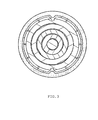
- the alignment guides 33 shown in Figure 3 , are rounded bumps placed along the inside of the reservoir 12, in which they match the existing recesses in the piston. In this way the piston moves along the reservoir 12 guided by the alignment guides 33.
- the telescopical spindle, the guide leaders 33 and the piston 10 are placed inside the reservoir, being that the piston 10 and the reservoir structure 12 form a container 34 for the lubricant fluid.
- the pistons 10 compression over the lubricant fluid the last exits through the sprue channel, and enters in the lubrication channels path.
- the telescopical spindle is referred as composed by 4 threaded cylinders.
- the applied number of cylinders of the telescopical spindle may vary, depending on the required pistons linear stroke, in order completely deplete the lubricant fluid.
- This versatility can also be applied to the gearboxes number of gears to achieve the desired transmission ratio.
- the reservoirs volume can also be modified depending on the amount of lubricant fluid desired.
Abstract
Description
- The present invention describes an automatic lubricator. Specifically, this device is intended to periodically release a quantity of lubricant fluid, according to the operating period set in the equipment, from 2 weeks to 52 weeks, with weekly increments. The device also allows the reprogramming of the previously programmed timing. Another added value of the presented automatic lubricator is the guarantee that the lubricating fluid is not subjected to high pressure when the system is on stand-by, thereby maintaining the fluids properties unchanged.
- The development of this automatic lubricator is related to the need to develop a device to bridge the functional disadvantages, described in the text that follows, of same type of equipments already in market.
- Most lubricators on the market are made up of plastic materials not compatible with each other and some mixed with metallic components, difficulting the recycling process.
- In the presented automatic lubricator, the mechanical components with the exception of electrical devices and some screws, are made of compatible plastic materials, uncontaminabled by lubricant fluid, provided that the fluids percentage is reduced. allowing the process of recycling plastics. These can be mixed and grinded at the same time, allowing the plastics recycling process. All electronic components and batteries will also have an appropriated recycling process.
- When the lubricant fluid is composed of lubricant grease it's necessary to ensure that the piston does not put the lubrication circuit in high pressure, so it doesn't change the grease properties, for example: the separation between oil, which is about 90% of the contents, and the absorbent material contained in the grease, such as lithium and sodium bentonite. To reduce this effect we contemplate reversing the electric motors rotation direction in order to relieve the grease from high pressure after an injection, through pistons withdraw. Lubricators are currently limited to inject the lubricant fluid without withdrawing the piston, thereby, the fluid is under high pressure over an extended period of time. The frequency in which a given amount of lubricant fluid is injected, is time variable, and depends on the characteristics of the mechanism to be lubricated. Considering the lubricator reservoirs dispensage in quantities that meet the lubrication mechanism needs, it's possible that the operations perfect period does not match with a known time unit. Therefore this lubricator contemplates operation period adjustment in weekly increments, to improve the lubricant fluid dispensing for a given mechanism. In general, the existent lubricators include monthly programmable periods.
- In addition to the devices operation setting period it can be reprogrammed, if it is not well adapted to the needs of the mechanism to lubricate. The electromechanical automatic lubricators are not currently allowing that functionality. Most of the existing electromechanical lubricators use manufacturer exclusive batteries with specific formats, to put the equipment in operation, which requires the user to buy batteries from the product manufacturer. The lubricator developed uses two lithium AA batteries 1.5 Volt each, facilitating the exchange of the same, provided that the replacement batteries have the equivalent characteristics to the originals.
- The operation and advantages of this invention will become clear with the detailed description that follows. To help understand the systems operation, the descriptions below have references to details in the showed pictures:
-
FIG.1 - Vertical section cut of the present invention; -
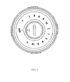
FIG.2 - View of the present invention user interface; -
FIG.3 - Planar view profile of the alignment guides, the telescopical system and the piston of the present invention. - In
picture 1 is possible to identify the several mechanical,electronics 24 and electrics systems and components automatic lubricator24. Starting from the initial OFF position when therotary programmer 26, shown inFigure 2 , is subject to rotation, theinternal power switch 1 is pressed by the action of an entrance ramp, whilepotentiometer 25 is also activated simultaneously. Following therotary programmer 26 rotational movement, from the point where theswitch 1 is pressed, will became able to turnprogrammer selector 26 to a maximum of 300 degrees being the output tension proportional the selector cursor. Circling thedial 26 is a graduated scale indicating the several operation modes, as well operating programmable time. From the possible operations mode, we are able to identify: OFF mode, where the lubricator is totally inactive and electrically disconnected from the battery 32; RESET mode (R), which after 5 seconds in this position the system resets elapsed time and the number of shots done; and a P mode, where the lubricator dispense on an ongoing basis until the occurrence of an alarm or inactivation of this feature. A selection range period is graduated to allow programming periods from 2 weeks to 52 weeks, with weekly increments.Potentiometer information 25 is communicated to amicrocontroller 28, which processes analog reading to digital data. Themicrocontroller 28 is the component which performs all calculations for lubricant fluid distribution within the scheduled period, being possible also, to change operating cycle during its function and recalculate the dispense frequency considering remaining quantity of lubricant fluid in the reservoir. This device monitorize also, the value of batteries voltage 32, in order to indicate when they have low tension. Lubricant fluid outer pressure is also monitorized based on the current consumed by the electrical motor 2. - Regarding the various parameters above mentioned, the
microcontroller 28 activates periodically the electric motor 2, to dispense lubricant fluid during the scheduled period. Given the mentioned variables, and through themicrocontroller calculation 28, is possible to generate alarm indicators related to malfunctions, such as: tension cells 32 under to 2.4V; depleted lubricant fluid and 10 bar injection pressure. Warning signals are represented byLEDs - Through the
device 27 andmicrocontroller 28 the motor runs in both rotational directions, because, each time the engine advances thepiston 10, and after this action is completed, it will perform a reverse rotational direction to retract the piston slightly 10, in order to prevent the lubricant fluid to remain on high pressure. To measure the linear advance of thepiston 10, which is primarily reflected in the amount of lubricant fluid depleted, there is anoptical sensor 31 which checks the number of rotation increments in the last gear 7, by counting to count through and by theshaft slots 22, which are coupled with referred gear. The movement transmission to the last gear 7 is carried out by a sequence of gears meshed 3,4,5,6,18,19,20 and 21, which transmit the rotational movement of the engine to the last gear 7, having these, appropriated features to achieve the desired final torque. In the last gear 7 exists asquare hole 8, which fits with one spindle with the same shape belonging to the telescopical spindle. - All above components are housed in a
support structure 23, which has at its base a number of slots, which prevent rotation between thestructure 23 of thelubricant fluid reservoir 12. Usingmultiple grooves 23 relates to the fact that the square of the telecopical spindle shaft fit into thesquare hole 8, which means they will only fit in steps of 90 degrees in 90 degrees, so a system with multiple slots is necessary in order to be possible in any position fromsquare hole 8, there is always necessary to block between 23 and 12 the rotational movement. To engage thesupport structure 23 to thereservoir 12, there is a capsule surrounding the 9outer structure 23, which by screwing on theexternal thread 15 located on top ofreservoir 12, performs the mechanical linkage between the two components. - Knowing that the electric motor 2 runs periodically controlled by the
microcontroller 28, and taking into account, that the motion transmission from the engine 2 to the final gear 7 is ensured by theintermediate gears square hole 8 will have a rotational movement transmitted to the telescopical spindle. - The telescopic system consists of several hollow cylinders with inner and outer thread, with the exception of the first 17, which is solid, with external thread and the last 13, which contains only internal threads. The
last cylinder 13 is coupled to thepiston 10, which contains an anti-rotation viaalignment guides 33. Thealignment guides 33, shown inFigure 3 , are rounded bumps placed along the inside of thereservoir 12, in which they match the existing recesses in the piston. In this way the piston moves along thereservoir 12 guided by thealignment guides 33. - Initially all
cylinders piston 10 is in the top. The rotational movement is transmitted to the telescopical spindlesfirst cylinder 17. When the first cylinder starts the movement, considering that theremaining cylinders last cylinder 13 is connected to thepiston 10, which does not rotate, means that thefirst cylinder 17 will begin to unscrew inside of thesecond cylinder 16 until it reaches a travel limiter characterized by a thread discontinuity. At this point, the first and second cylinders (17 and 16) become solidarily bounded, meaning that they will run together as one, and begin to unscrew inside thethird cylinder 14. This operation is repeated between all cylinders threaded till thepiston 10 reaches its maximum displacement. During unscrewing process for thevarious cylinders piston 10 moves proportionally to the cylinders thread pitch, and the rotation speed provided by the electrical motor, divided by the gearbox ratio. - The telescopical spindle, the
guide leaders 33 and thepiston 10 are placed inside the reservoir, being that thepiston 10 and thereservoir structure 12 form acontainer 34 for the lubricant fluid. By thepistons 10 compression over the lubricant fluid, the last exits through the sprue channel, and enters in the lubrication channels path. - Up until now, the telescopical spindle is referred as composed by 4 threaded cylinders. However, the applied number of cylinders of the telescopical spindle may vary, depending on the required pistons linear stroke, in order completely deplete the lubricant fluid. This versatility can also be applied to the gearboxes number of gears to achieve the desired transmission ratio. The reservoirs volume can also be modified depending on the amount of lubricant fluid desired.
Claims (7)
- The automatic lubricator with telescopical spindle, which functioning is characterized in the detailed description, composed by an appropriate number of cylinders with variable dimensions that convert a rotational motion into a linear one in order to promote the pistons stroke.
- The automatic lubricator defined by the fact that has a rotating selector that works as a programming device for the dispensing period, as well as the desirable functioning mode.
- The automatic lubricator mentioned in the previous claim prepared equally to accept weekly programmed values.
- The automatic lubricator defined by the fact that has a microcontroller developed in a way that allows the reprogramming of the functioning period and the consequent temporal redistribution of the remaining amount of lubricant fluid.
- The automatic lubricator defined by the fact that has microcontroller programmed to allow the withdrawal of the piston, after each lubricant fluid dispense, by inversion of the electrical motors rotation direction, in order to relieve the lubricant fluid from high pressures.
- The automatic lubricator equipped with a mechanical system that uses a gearbox free electrical motor, and uses coupled gears that confer a specific torque to the piston causing higher or lower pressure at the lubricant fluids exit, depending on the gears specification.
- The automatic lubricator defined by be equipped with an anti-rotating system for the piston, composed by rounded shape guide leaders, placed along the interior of the lubricant fluid reservoir, being that the piston will have slots disposed in the same direction, in order to fit in the reservoirs interior, and move linear wise, guided by the mentioned guide leaders.
Priority Applications (2)
| Application Number | Priority Date | Filing Date | Title |
|---|---|---|---|
| EP20090398019 EP2333397B1 (en) | 2009-12-11 | 2009-12-11 | Automatic lubricator |
| PT09398019T PT2333397E (en) | 2009-12-11 | 2009-12-11 | Automatic lubricator |
Applications Claiming Priority (1)
| Application Number | Priority Date | Filing Date | Title |
|---|---|---|---|
| EP20090398019 EP2333397B1 (en) | 2009-12-11 | 2009-12-11 | Automatic lubricator |
Publications (2)
| Publication Number | Publication Date |
|---|---|
| EP2333397A1 true EP2333397A1 (en) | 2011-06-15 |
| EP2333397B1 EP2333397B1 (en) | 2013-03-20 |
Family
ID=42121401
Family Applications (1)
| Application Number | Title | Priority Date | Filing Date |
|---|---|---|---|
| EP20090398019 Not-in-force EP2333397B1 (en) | 2009-12-11 | 2009-12-11 | Automatic lubricator |
Country Status (2)
| Country | Link |
|---|---|
| EP (1) | EP2333397B1 (en) |
| PT (1) | PT2333397E (en) |
Cited By (2)
| Publication number | Priority date | Publication date | Assignee | Title |
|---|---|---|---|---|
| JP2015507730A (en) * | 2012-01-03 | 2015-03-12 | ペルマ−テク・ゲゼルシヤフト・ミト・ベシユレンクテル・ハフツング・ウント・コンパニー・コマンデイトゲゼルシヤフト | Lubricant dispenser |
| CN113574306A (en) * | 2019-03-15 | 2021-10-29 | 佩玛技术两合有限公司 | Lubricant distributor |
Citations (4)
| Publication number | Priority date | Publication date | Assignee | Title |
|---|---|---|---|---|
| US5271528A (en) * | 1992-10-12 | 1993-12-21 | Hornche Trading Co., Ltd. | Automatic grease dispenser |
| US6125969A (en) * | 1997-12-23 | 2000-10-03 | Perma-Tec Gmbh & Co. Kg | Method of and apparatus for lubricating an apparatus having a number of lubricant locations |
| EP1213529A1 (en) * | 2000-12-07 | 2002-06-12 | Perma-Tec GmbH & Co. KG | Lubricant dispenser |
| WO2004001279A1 (en) * | 2002-06-19 | 2003-12-31 | Perma-Tec Gmbh & Co. Kg | Dosing device for lubricant |
-
2009
- 2009-12-11 PT PT09398019T patent/PT2333397E/en unknown
- 2009-12-11 EP EP20090398019 patent/EP2333397B1/en not_active Not-in-force
Patent Citations (4)
| Publication number | Priority date | Publication date | Assignee | Title |
|---|---|---|---|---|
| US5271528A (en) * | 1992-10-12 | 1993-12-21 | Hornche Trading Co., Ltd. | Automatic grease dispenser |
| US6125969A (en) * | 1997-12-23 | 2000-10-03 | Perma-Tec Gmbh & Co. Kg | Method of and apparatus for lubricating an apparatus having a number of lubricant locations |
| EP1213529A1 (en) * | 2000-12-07 | 2002-06-12 | Perma-Tec GmbH & Co. KG | Lubricant dispenser |
| WO2004001279A1 (en) * | 2002-06-19 | 2003-12-31 | Perma-Tec Gmbh & Co. Kg | Dosing device for lubricant |
Cited By (3)
| Publication number | Priority date | Publication date | Assignee | Title |
|---|---|---|---|---|
| JP2015507730A (en) * | 2012-01-03 | 2015-03-12 | ペルマ−テク・ゲゼルシヤフト・ミト・ベシユレンクテル・ハフツング・ウント・コンパニー・コマンデイトゲゼルシヤフト | Lubricant dispenser |
| CN113574306A (en) * | 2019-03-15 | 2021-10-29 | 佩玛技术两合有限公司 | Lubricant distributor |
| CN113574306B (en) * | 2019-03-15 | 2023-10-03 | 佩玛技术两合有限公司 | Lubricant dispenser |
Also Published As
| Publication number | Publication date |
|---|---|
| EP2333397B1 (en) | 2013-03-20 |
| PT2333397E (en) | 2013-06-20 |
Similar Documents
| Publication | Publication Date | Title |
|---|---|---|
| US10201830B2 (en) | Dispensing device | |
| US6601738B2 (en) | Lubricant dispenser | |
| CN100444908C (en) | Injection device | |
| US20170259485A1 (en) | Extrusion device | |
| KR101546379B1 (en) | Oil injection device | |
| CN104010736A (en) | Driving device of a dosing and mixing device | |
| EP2333397A1 (en) | Automatic lubricator | |
| JP2003528277A (en) | Lubrication device | |
| CN104080545A (en) | A motorized viscous material dispenser and a method of operating a dispenser | |
| US20210015996A1 (en) | Method and devices for delivering insulin | |
| US20140224587A1 (en) | Fluid Holder And Electromechanical Lubricator Employing Same | |
| CN201636514U (en) | Quantitative oil filling machine | |
| US20150114992A1 (en) | Grease gun with sensing capability and variable speed | |
| WO2005017356A1 (en) | Dispensing pump having servo driven linear actuator | |
| DE4321452C1 (en) | Automatically dispensing lubricant or other media or suitable for metering electromechanically driven device | |
| US20100217446A1 (en) | Fluid Holder And Electromechanical Lubricator Employing Same | |
| CN202660207U (en) | Automatic lubricating device | |
| CN211502275U (en) | Part oiling equipment in gap for machining | |
| CN209210350U (en) | The extruding injection device of high-viscosity paste | |
| CN212080823U (en) | Oil ejector | |
| CN219063066U (en) | Multi-channel lubricating grease filling intelligent distributing valve | |
| CN109437075A (en) | The extruding injection device of high-viscosity paste | |
| CN216693006U (en) | Automatic grease filling device | |
| CN211901536U (en) | Gear oiling lubricating device of transmission machinery | |
| CN208620038U (en) | A kind of new automatic oil syringe |
Legal Events
| Date | Code | Title | Description |
|---|---|---|---|
| PUAI | Public reference made under article 153(3) epc to a published international application that has entered the european phase |
Free format text: ORIGINAL CODE: 0009012 |
|
| AK | Designated contracting states |
Kind code of ref document: A1 Designated state(s): AT BE BG CH CY CZ DE DK EE ES FI FR GB GR HR HU IE IS IT LI LT LU LV MC MK MT NL NO PL PT RO SE SI SK SM TR |
|
| AX | Request for extension of the european patent |
Extension state: AL BA RS |
|
| RIN1 | Information on inventor provided before grant (corrected) |
Inventor name: GOMES DE FIGUEIREDO, CARLOS JOAO |
|
| 17P | Request for examination filed |
Effective date: 20111130 |
|
| GRAP | Despatch of communication of intention to grant a patent |
Free format text: ORIGINAL CODE: EPIDOSNIGR1 |
|
| GRAS | Grant fee paid |
Free format text: ORIGINAL CODE: EPIDOSNIGR3 |
|
| GRAA | (expected) grant |
Free format text: ORIGINAL CODE: 0009210 |
|
| AK | Designated contracting states |
Kind code of ref document: B1 Designated state(s): AT BE BG CH CY CZ DE DK EE ES FI FR GB GR HR HU IE IS IT LI LT LU LV MC MK MT NL NO PL PT RO SE SI SK SM TR |
|
| REG | Reference to a national code |
Ref country code: GB Ref legal event code: FG4D |
|
| REG | Reference to a national code |
Ref country code: CH Ref legal event code: EP |
|
| REG | Reference to a national code |
Ref country code: IE Ref legal event code: FG4D |
|
| REG | Reference to a national code |
Ref country code: AT Ref legal event code: REF Ref document number: 602306 Country of ref document: AT Kind code of ref document: T Effective date: 20130415 |
|
| REG | Reference to a national code |
Ref country code: DE Ref legal event code: R096 Ref document number: 602009014142 Country of ref document: DE Effective date: 20130516 |
|
| REG | Reference to a national code |
Ref country code: PT Ref legal event code: SC4A Free format text: AVAILABILITY OF NATIONAL TRANSLATION Effective date: 20130611 |
|
| PG25 | Lapsed in a contracting state [announced via postgrant information from national office to epo] |
Ref country code: LT Free format text: LAPSE BECAUSE OF FAILURE TO SUBMIT A TRANSLATION OF THE DESCRIPTION OR TO PAY THE FEE WITHIN THE PRESCRIBED TIME-LIMIT Effective date: 20130320 Ref country code: BG Free format text: LAPSE BECAUSE OF FAILURE TO SUBMIT A TRANSLATION OF THE DESCRIPTION OR TO PAY THE FEE WITHIN THE PRESCRIBED TIME-LIMIT Effective date: 20130620 Ref country code: NO Free format text: LAPSE BECAUSE OF FAILURE TO SUBMIT A TRANSLATION OF THE DESCRIPTION OR TO PAY THE FEE WITHIN THE PRESCRIBED TIME-LIMIT Effective date: 20130620 Ref country code: ES Free format text: LAPSE BECAUSE OF FAILURE TO SUBMIT A TRANSLATION OF THE DESCRIPTION OR TO PAY THE FEE WITHIN THE PRESCRIBED TIME-LIMIT Effective date: 20130701 Ref country code: SE Free format text: LAPSE BECAUSE OF FAILURE TO SUBMIT A TRANSLATION OF THE DESCRIPTION OR TO PAY THE FEE WITHIN THE PRESCRIBED TIME-LIMIT Effective date: 20130320 |
|
| REG | Reference to a national code |
Ref country code: AT Ref legal event code: MK05 Ref document number: 602306 Country of ref document: AT Kind code of ref document: T Effective date: 20130320 |
|
| REG | Reference to a national code |
Ref country code: LT Ref legal event code: MG4D |
|
| PG25 | Lapsed in a contracting state [announced via postgrant information from national office to epo] |
Ref country code: SI Free format text: LAPSE BECAUSE OF FAILURE TO SUBMIT A TRANSLATION OF THE DESCRIPTION OR TO PAY THE FEE WITHIN THE PRESCRIBED TIME-LIMIT Effective date: 20130320 Ref country code: LV Free format text: LAPSE BECAUSE OF FAILURE TO SUBMIT A TRANSLATION OF THE DESCRIPTION OR TO PAY THE FEE WITHIN THE PRESCRIBED TIME-LIMIT Effective date: 20130320 Ref country code: FI Free format text: LAPSE BECAUSE OF FAILURE TO SUBMIT A TRANSLATION OF THE DESCRIPTION OR TO PAY THE FEE WITHIN THE PRESCRIBED TIME-LIMIT Effective date: 20130320 |
|
| REG | Reference to a national code |
Ref country code: NL Ref legal event code: VDEP Effective date: 20130320 |
|
| PG25 | Lapsed in a contracting state [announced via postgrant information from national office to epo] |
Ref country code: BE Free format text: LAPSE BECAUSE OF FAILURE TO SUBMIT A TRANSLATION OF THE DESCRIPTION OR TO PAY THE FEE WITHIN THE PRESCRIBED TIME-LIMIT Effective date: 20130320 Ref country code: HR Free format text: LAPSE BECAUSE OF FAILURE TO SUBMIT A TRANSLATION OF THE DESCRIPTION OR TO PAY THE FEE WITHIN THE PRESCRIBED TIME-LIMIT Effective date: 20130320 |
|
| PG25 | Lapsed in a contracting state [announced via postgrant information from national office to epo] |
Ref country code: IS Free format text: LAPSE BECAUSE OF FAILURE TO SUBMIT A TRANSLATION OF THE DESCRIPTION OR TO PAY THE FEE WITHIN THE PRESCRIBED TIME-LIMIT Effective date: 20130720 Ref country code: EE Free format text: LAPSE BECAUSE OF FAILURE TO SUBMIT A TRANSLATION OF THE DESCRIPTION OR TO PAY THE FEE WITHIN THE PRESCRIBED TIME-LIMIT Effective date: 20130320 Ref country code: CZ Free format text: LAPSE BECAUSE OF FAILURE TO SUBMIT A TRANSLATION OF THE DESCRIPTION OR TO PAY THE FEE WITHIN THE PRESCRIBED TIME-LIMIT Effective date: 20130320 Ref country code: AT Free format text: LAPSE BECAUSE OF FAILURE TO SUBMIT A TRANSLATION OF THE DESCRIPTION OR TO PAY THE FEE WITHIN THE PRESCRIBED TIME-LIMIT Effective date: 20130320 Ref country code: NL Free format text: LAPSE BECAUSE OF FAILURE TO SUBMIT A TRANSLATION OF THE DESCRIPTION OR TO PAY THE FEE WITHIN THE PRESCRIBED TIME-LIMIT Effective date: 20130320 Ref country code: RO Free format text: LAPSE BECAUSE OF FAILURE TO SUBMIT A TRANSLATION OF THE DESCRIPTION OR TO PAY THE FEE WITHIN THE PRESCRIBED TIME-LIMIT Effective date: 20130320 Ref country code: SK Free format text: LAPSE BECAUSE OF FAILURE TO SUBMIT A TRANSLATION OF THE DESCRIPTION OR TO PAY THE FEE WITHIN THE PRESCRIBED TIME-LIMIT Effective date: 20130320 |
|
| PG25 | Lapsed in a contracting state [announced via postgrant information from national office to epo] |
Ref country code: PL Free format text: LAPSE BECAUSE OF FAILURE TO SUBMIT A TRANSLATION OF THE DESCRIPTION OR TO PAY THE FEE WITHIN THE PRESCRIBED TIME-LIMIT Effective date: 20130320 Ref country code: CY Free format text: LAPSE BECAUSE OF FAILURE TO SUBMIT A TRANSLATION OF THE DESCRIPTION OR TO PAY THE FEE WITHIN THE PRESCRIBED TIME-LIMIT Effective date: 20130320 |
|
| PLBI | Opposition filed |
Free format text: ORIGINAL CODE: 0009260 |
|
| PLAX | Notice of opposition and request to file observation + time limit sent |
Free format text: ORIGINAL CODE: EPIDOSNOBS2 |
|
| PG25 | Lapsed in a contracting state [announced via postgrant information from national office to epo] |
Ref country code: DK Free format text: LAPSE BECAUSE OF FAILURE TO SUBMIT A TRANSLATION OF THE DESCRIPTION OR TO PAY THE FEE WITHIN THE PRESCRIBED TIME-LIMIT Effective date: 20130320 |
|
| 26 | Opposition filed |
Opponent name: PERMA-TEC GMBH & CO. KG Effective date: 20131220 |
|
| PG25 | Lapsed in a contracting state [announced via postgrant information from national office to epo] |
Ref country code: IT Free format text: LAPSE BECAUSE OF FAILURE TO SUBMIT A TRANSLATION OF THE DESCRIPTION OR TO PAY THE FEE WITHIN THE PRESCRIBED TIME-LIMIT Effective date: 20130320 |
|
| REG | Reference to a national code |
Ref country code: DE Ref legal event code: R026 Ref document number: 602009014142 Country of ref document: DE Effective date: 20131220 |
|
| REG | Reference to a national code |
Ref country code: DE Ref legal event code: R119 Ref document number: 602009014142 Country of ref document: DE |
|
| REG | Reference to a national code |
Ref country code: CH Ref legal event code: PL |
|
| GBPC | Gb: european patent ceased through non-payment of renewal fee |
Effective date: 20131211 |
|
| PG25 | Lapsed in a contracting state [announced via postgrant information from national office to epo] |
Ref country code: MC Free format text: LAPSE BECAUSE OF FAILURE TO SUBMIT A TRANSLATION OF THE DESCRIPTION OR TO PAY THE FEE WITHIN THE PRESCRIBED TIME-LIMIT Effective date: 20130320 Ref country code: LU Free format text: LAPSE BECAUSE OF FAILURE TO SUBMIT A TRANSLATION OF THE DESCRIPTION OR TO PAY THE FEE WITHIN THE PRESCRIBED TIME-LIMIT Effective date: 20131211 |
|
| REG | Reference to a national code |
Ref country code: IE Ref legal event code: MM4A |
|
| REG | Reference to a national code |
Ref country code: FR Ref legal event code: ST Effective date: 20140829 |
|
| REG | Reference to a national code |
Ref country code: DE Ref legal event code: R119 Ref document number: 602009014142 Country of ref document: DE Effective date: 20140701 |
|
| PG25 | Lapsed in a contracting state [announced via postgrant information from national office to epo] |
Ref country code: LI Free format text: LAPSE BECAUSE OF NON-PAYMENT OF DUE FEES Effective date: 20131231 Ref country code: CH Free format text: LAPSE BECAUSE OF NON-PAYMENT OF DUE FEES Effective date: 20131231 Ref country code: DE Free format text: LAPSE BECAUSE OF NON-PAYMENT OF DUE FEES Effective date: 20140701 Ref country code: IE Free format text: LAPSE BECAUSE OF NON-PAYMENT OF DUE FEES Effective date: 20131211 |
|
| PG25 | Lapsed in a contracting state [announced via postgrant information from national office to epo] |
Ref country code: GB Free format text: LAPSE BECAUSE OF NON-PAYMENT OF DUE FEES Effective date: 20131211 Ref country code: FR Free format text: LAPSE BECAUSE OF NON-PAYMENT OF DUE FEES Effective date: 20131231 |
|
| PGFP | Annual fee paid to national office [announced via postgrant information from national office to epo] |
Ref country code: PT Payment date: 20141105 Year of fee payment: 6 |
|
| PG25 | Lapsed in a contracting state [announced via postgrant information from national office to epo] |
Ref country code: SM Free format text: LAPSE BECAUSE OF FAILURE TO SUBMIT A TRANSLATION OF THE DESCRIPTION OR TO PAY THE FEE WITHIN THE PRESCRIBED TIME-LIMIT Effective date: 20130320 |
|
| PG25 | Lapsed in a contracting state [announced via postgrant information from national office to epo] |
Ref country code: TR Free format text: LAPSE BECAUSE OF FAILURE TO SUBMIT A TRANSLATION OF THE DESCRIPTION OR TO PAY THE FEE WITHIN THE PRESCRIBED TIME-LIMIT Effective date: 20130320 |
|
| PG25 | Lapsed in a contracting state [announced via postgrant information from national office to epo] |
Ref country code: HU Free format text: LAPSE BECAUSE OF FAILURE TO SUBMIT A TRANSLATION OF THE DESCRIPTION OR TO PAY THE FEE WITHIN THE PRESCRIBED TIME-LIMIT; INVALID AB INITIO Effective date: 20091211 Ref country code: MK Free format text: LAPSE BECAUSE OF FAILURE TO SUBMIT A TRANSLATION OF THE DESCRIPTION OR TO PAY THE FEE WITHIN THE PRESCRIBED TIME-LIMIT Effective date: 20130320 |
|
| PG25 | Lapsed in a contracting state [announced via postgrant information from national office to epo] |
Ref country code: GR Free format text: LAPSE BECAUSE OF NON-PAYMENT OF DUE FEES Effective date: 20130320 Ref country code: MT Free format text: LAPSE BECAUSE OF FAILURE TO SUBMIT A TRANSLATION OF THE DESCRIPTION OR TO PAY THE FEE WITHIN THE PRESCRIBED TIME-LIMIT Effective date: 20130320 |
|
| RAP2 | Party data changed (patent owner data changed or rights of a patent transferred) |
Owner name: CARFI - FABRICA DE PLASTICOS E MOLDES, SA |
|
| REG | Reference to a national code |
Ref country code: PT Ref legal event code: MM4A Free format text: LAPSE DUE TO NON-PAYMENT OF FEES Effective date: 20160613 |
|
| PLAB | Opposition data, opponent's data or that of the opponent's representative modified |
Free format text: ORIGINAL CODE: 0009299OPPO |
|
| R26 | Opposition filed (corrected) |
Opponent name: PERMA-TEC GMBH & CO. KG Effective date: 20131220 |
|
| PG25 | Lapsed in a contracting state [announced via postgrant information from national office to epo] |
Ref country code: PT Free format text: LAPSE BECAUSE OF NON-PAYMENT OF DUE FEES Effective date: 20160613 |
|
| PLBD | Termination of opposition procedure: decision despatched |
Free format text: ORIGINAL CODE: EPIDOSNOPC1 |
|
| REG | Reference to a national code |
Ref country code: DE Ref legal event code: R100 Ref document number: 602009014142 Country of ref document: DE |
|
| PLBM | Termination of opposition procedure: date of legal effect published |
Free format text: ORIGINAL CODE: 0009276 |
|
| STAA | Information on the status of an ep patent application or granted ep patent |
Free format text: STATUS: OPPOSITION PROCEDURE CLOSED |
|
| 27C | Opposition proceedings terminated |
Effective date: 20161217 |