EP2460449A1 - A beverage preparation machine with automatic cleaning system - Google Patents
A beverage preparation machine with automatic cleaning system Download PDFInfo
- Publication number
- EP2460449A1 EP2460449A1 EP10193797A EP10193797A EP2460449A1 EP 2460449 A1 EP2460449 A1 EP 2460449A1 EP 10193797 A EP10193797 A EP 10193797A EP 10193797 A EP10193797 A EP 10193797A EP 2460449 A1 EP2460449 A1 EP 2460449A1
- Authority
- EP
- European Patent Office
- Prior art keywords
- channel
- machine
- liquid
- cleaning member
- elongated
- Prior art date
- Legal status (The legal status is an assumption and is not a legal conclusion. Google has not performed a legal analysis and makes no representation as to the accuracy of the status listed.)
- Withdrawn
Links
Images

Classifications
-
- A—HUMAN NECESSITIES
- A47—FURNITURE; DOMESTIC ARTICLES OR APPLIANCES; COFFEE MILLS; SPICE MILLS; SUCTION CLEANERS IN GENERAL
- A47J—KITCHEN EQUIPMENT; COFFEE MILLS; SPICE MILLS; APPARATUS FOR MAKING BEVERAGES
- A47J31/00—Apparatus for making beverages
- A47J31/44—Parts or details or accessories of beverage-making apparatus
- A47J31/60—Cleaning devices
-
- A—HUMAN NECESSITIES
- A47—FURNITURE; DOMESTIC ARTICLES OR APPLIANCES; COFFEE MILLS; SPICE MILLS; SUCTION CLEANERS IN GENERAL
- A47J—KITCHEN EQUIPMENT; COFFEE MILLS; SPICE MILLS; APPARATUS FOR MAKING BEVERAGES
- A47J31/00—Apparatus for making beverages
- A47J31/24—Coffee-making apparatus in which hot water is passed through the filter under pressure, i.e. in which the coffee grounds are extracted under pressure
- A47J31/34—Coffee-making apparatus in which hot water is passed through the filter under pressure, i.e. in which the coffee grounds are extracted under pressure with hot water under liquid pressure
- A47J31/36—Coffee-making apparatus in which hot water is passed through the filter under pressure, i.e. in which the coffee grounds are extracted under pressure with hot water under liquid pressure with mechanical pressure-producing means
- A47J31/3666—Coffee-making apparatus in which hot water is passed through the filter under pressure, i.e. in which the coffee grounds are extracted under pressure with hot water under liquid pressure with mechanical pressure-producing means whereby the loading of the brewing chamber with the brewing material is performed by the user
- A47J31/3676—Cartridges being employed
- A47J31/369—Impermeable cartridges being employed
- A47J31/3695—Cartridge perforating means for creating the hot water inlet
-
- B—PERFORMING OPERATIONS; TRANSPORTING
- B08—CLEANING
- B08B—CLEANING IN GENERAL; PREVENTION OF FOULING IN GENERAL
- B08B9/00—Cleaning hollow articles by methods or apparatus specially adapted thereto
- B08B9/02—Cleaning pipes or tubes or systems of pipes or tubes
- B08B9/027—Cleaning the internal surfaces; Removal of blockages
- B08B9/04—Cleaning the internal surfaces; Removal of blockages using cleaning devices introduced into and moved along the pipes
- B08B9/043—Cleaning the internal surfaces; Removal of blockages using cleaning devices introduced into and moved along the pipes moved by externally powered mechanical linkage, e.g. pushed or drawn through the pipes
- B08B9/0436—Cleaning the internal surfaces; Removal of blockages using cleaning devices introduced into and moved along the pipes moved by externally powered mechanical linkage, e.g. pushed or drawn through the pipes provided with mechanical cleaning tools, e.g. scrapers, with or without additional fluid jets
Definitions
- the present invention concerns a beverage system including a beverage preparation machine for preparing a beverage by injection of a liquid into an ingredient capsule.
- An ingredient capsule contains food ingredients or substances that are used by addition of a liquid for preparing a beverage or, to a larger extent, liquid comestibles.
- a beverage preparation machine comprises a receptacle for accommodating a capsule and a fluid injection system for injecting a fluid, preferably a liquid such as water, under pressure into said capsule.
- a fluid preferably a liquid such as water
- water injected under pressure in the capsule, for the preparation of a coffee beverage is preferably hot, that is to say at a temperature above 70°C.
- water might also be at ambient temperature.
- the pressure inside the capsule during extraction and/or dissolution of the capsule ingredient(s) is typically about 1 to 6 bar for dissolution products, and 2 to 12 bar for extraction of roasted and grounded coffee.
- Such a preparation process greatly differs from the so-called "brewing" process of beverage preparation - particularly for tea and coffee, in that brewing requires a long time of infusion of the ingredient(s) by a fluid (e.g. hot water), whereas the beverage preparation process allows a consumer to prepare a beverage, for example coffee, within a few seconds.
- a fluid e.g. hot water
- the principle of extracting and/or dissolving the ingredient(s) of a closed capsule under pressure is known and consists typically of inserting the capsule into a receptacle of a machine, injecting a quantity of pressurized water into the capsule, so as to create a pressurized environment inside the capsule either to extract the ingredient(s) or dissolve it, and then release the extracted ingredient(s) or the dissolved ingredient(s) through the capsule.
- Capsules of this type have already been described for example in the Applicant's European patents 1 472 156 B1 , and 1 784 344 B1 .
- a beverage preparation machine comprises a receptacle for accommodating a capsule and a piercing and injection element made in the form of a hollow needle comprising in its distal region one or more liquid injection orifices.
- the hollow needle has a dual function in that it pierces and therefore opens the top portion of the capsule on the one hand, and forms through inlet channel inside the needle enabling water to flow through to the distal region the capsule for being injected thereinto on the other hand.
- a capsule may contain roast and ground coffee powder as an ingredient, which is to be extracted thanks to hot water injected therein.
- a capsule of this type typically comprises:
- beverage preparation machine of the above-described kind uses water as extraction fluid scaling deposits are formed in the parts of the machine which are in contact with water that is the water circulation system.
- This pin-shaped member has an outside diameter which corresponds to the internal diameter of the needle channel taking account of the mechanical tolerance.
- Machines' user guide provides consumers with instructions as to how regularly use this cleaning tool in order to avoid scaling and therefore subsequent clogging of the machines.
- the invention concerns a beverage preparation system for preparing a beverage by injection of a liquid into an ingredient capsule, the beverage system comprising an ingredient capsule and a beverage preparation machine having:
- the system is conceived so that cleaning of the at least one inner through channel is automatically operated, i.e. without any human intervention dedicated to cleaning.
- the only human intervention is that one necessary for operating the beverage preparation machine with a view to preparing a beverage.
- cleaning the at least one inner through channel means cleaning the internal surface of the wall that delimits the inner through channel and on which deposits may get accumulated.
- the cleaning device has an elongated cleaning member, actuation of said cleaning device causing said elongated cleaning member to slide within the at least one inner through channel.
- the sliding movement of the elongated cleaning member within the at least one inner through channel makes it possible to remove any deposits that may get accumulated on the internal surface of the wall surrounding said channel.
- the cleaning operation is automatically triggered when operating means for causing the beverage preparation machine to prepare a beverage are actuated.
- the present invention suppresses human intervention for cleaning the injection unit and, therefore, makes cleaning more regular and more reliable than in the past.
- the cleaning device does not use any additional energy source for being operated.
- the cleaning device does not modify the current operation of the beverage preparation machine for preparing beverages. It is just easily and conveniently interfaced with the current mechanism of the machine.
- the injection unit may be traversed by several inner channels and, correspondingly, the cleaning device may include several elongated cleaning members each being intended to be inserted in a channel for cleaning thereof.
- the elongated cleaning member is able to automatically occupy two positions, a first active position in which said elongated cleaning member extends within the at least one inner through channel through to the free emerging end thereof, and a second rest position in which said elongated cleaning member is at least partly withdrawn from said at least one inner through channel.
- actuation of the cleaning device causes the elongated cleaning member to occupy either of the two positions depending on the position of said elongated cleaning member when starting actuation of the cleaning device.
- the elongated cleaning member may be in the first active position and will move to the second rest position upon actuation of said operating means.
- the starting position of the elongated cleaning member may be the second rest position before actuating the operating means.
- the at least one inner through channel comprises at least two channel portions, a first channel portion including the free emerging end of said at least one inner through channel and having a first inner diameter, and at least one upstream channel portion disposed upstream said first channel portion and having an enlarged second inner diameter.
- the first channel portion has preferably a reduced diameter which is suitable for producing a jet of liquid when exiting the free emerging end of the channel.
- the upstream channel portion (e.g. second channel portion) has preferably an enlarged inner diameter.
- the at least one inner through channel may further comprise a third channel portion disposed upstream a second channel portion and having an enlarged third inner diameter.
- the length of the first channel portion must be sufficient to produce a jet of liquid but must not be too long in order to avoid augmenting the risks of scaling deposits accumulation inside.
- this intermediary channel portion of intermediary diameter makes it possible to have a thinner outer size for the injection unit close to the free emerging end of the channel, which is more favourable to the piercing (or puncturing or tearing, etc) of an ingredient capsule.
- the elongated cleaning member has a free extremity which, in the second rest position, is located in the at least upstream channel portion (e.g. a second channel portion).
- the free extremity of the elongated cleaning member may be, in the second rest position, located in the third channel portion.
- the elongated cleaning member has an outside diameter which substantially fits the first inner diameter of the first channel portion while enabling sliding of said elongated cleaning member thereinto.
- the transverse dimension of the elongated cleaning member (e.g. its diameter) is adjusted to the first inner diameter of the first channel portion for efficiently cleaning the surface of the internal wall defining this channel portion thanks to a sliding movement within said channel portion.
- the risks of clogging of the channel portions may arise, in particular, in the portion of reduced diameter, that is the first channel portion.
- the other upstream located channel portions are less prone to clogging.
- said operating means comprise actuation means for actuating the machine from a first open position in which said machine is open for enabling introduction of the ingredient capsule thereinto to a second closed position in which said machine is closed and the ingredient capsule is inside said machine for liquid injection, and vice versa, said cleaning device being actuated by said actuation means.
- cleaning takes place when opening the machine for introducing an ingredient capsule thereinto and after the beverage has been prepared, when opening the machine again for removing the used ingredient capsule.
- This embodiment is advantageous in that cleaning is merely triggered when opening and/or closing the machine.
- the injection unit in the first open position of the machine the injection unit may be in a high position and in the second closed position the injection unit may be in a low position.
- the injection unit is therefore moved from a high to a low position when closing the machine or from a low to a high position when opening the latter.
- the elongated cleaning member and the injection unit are movable relative to one another when the machine is actuated from the first open position to the second closed position and vice versa.
- the elongated cleaning member and the injection unit are movable relative to one another so that the elongated cleaning member may slide within the at least one inner through channel.
- the elongated cleaning member and the injection unit are connected to a part of the beverage preparation machine (e.g. the extraction head) which is movable between the first open position and the second closed position.
- the cleaning device has a support member to which the elongated cleaning member is connected, said support member being movable relative to the injection unit over a reduced path so that the elongated cleaning member is only withdrawn in part from said at least one inner through channel in its second position.
- This arrangement is advantageous in that a small displacement of the support member and the elongated cleaning member with respect to the injection unit is sufficient to enable efficient cleaning of the at least one inner through channel through a sliding movement.
- this arrangement is made possible since in the second position of the elongated cleaning member its free extremity is located in an upstream channel portion enabling passage of liquid through to the free emerging end of the inner through channel and, therefore, injection of said liquid into the ingredient capsule.
- the support member has two opposed ends, one end being connected to the elongated cleaning member and the other opposed end being linked with guiding means which are connected to the machine, said other opposed end being slidably guided over said reduced path when the machine is actuated from the first open position to the second closed position, and vice versa.
- the support member is therefore guided by its opposed end over a reduced path which is defined by two stops which are disposed at the opposed ends of a guiding rail or slot.
- the beverage preparation machine has:
- cleaning may automatically take place based on the actuation by liquid pumped from the liquid source towards the injection unit.
- This self-cleaning operation is made possible every cycle of beverage preparation by use of the pressure of the liquid that is pumped and injected into the capsule.
- the elongated cleaning member When liquid is no longer injected into the capsule and therefore the liquid pressure is very low, the elongated cleaning member is then automatically urged to be more deeply re-inserted into the at least one inner through channel without any human intervention.
- This reciprocating motion of the elongated cleaning member enables rubbing of the inner surface of the wall of the at least one inner channel and, therefore, removal of any deposits (e.g. scaling deposits when the liquid is water) that may get accumulated on the surface of the wall.
- the transverse dimension of the elongated cleaning member (e.g. a pin) roughly corresponds to the inner diameter of the at least one inner through channel in its narrower portion taking account of the mechanical clearance.
- the injection unit is a piercing and injection unit that includes a piercing or puncturing member for piercing or puncturing an ingredient capsule, the at least one inner through channel being formed in said piercing or puncturing member. Liquid is therefore injected into the capsule after piercing or puncturing thereof.
- the elongated cleaning member is able to automatically occupy said two positions depending on the injection or not of liquid into the at least one inner through channel, said elongated cleaning member being in said first active position in the absence of liquid injection thereinto, said elongated cleaning member being in said second active position due to the pressure of liquid injected into the at least one inner through channel.
- the elongated cleaning member is in either position according to the actuation of liquid injection or not.
- the cleaning device includes active means for exerting upon the elongated cleaning a first predetermined force (F1) so as to urge said elongated cleaning member to be inserted into the at least one inner through channel with a view to occupying the first active position.
- F1 first predetermined force
- active means e.g. resilient means
- These active means are permanently integrated in the machine so as to permanently exert the first predetermined force on the elongated cleaning member whatever the status of operation of the liquid injection process, thereby meaning that the liquid may be in the course of injection or not.
- liquid pressure does not always act on the elongated cleaning member.
- the elongated cleaning member tends to be inserted into the at least one inner through channel out of mere conception of the cleaning device.
- the elongated cleaning member is able to be pushed backwards under the action of the pressure of the liquid to be injected into the at least one inner through channel and which counteracts the first predetermined force so that the elongated cleaning member is at least partly withdrawn from said at least one inner through channel.
- the liquid pressure acts on the cleaning device member (e.g. to which the elongated cleaning member is connected) to counteract the first predetermined force and push back the elongated cleaning member to its rest position.
- the cleaning device member e.g. to which the elongated cleaning member is connected
- liquid pressure applies a second force to the cleaning device that is greater in intensity than the first one and opposed in direction.
- the cleaning device comprises a support member to which the elongated cleaning member is connected.
- the support member has a substantially cylindrical shape that is elongated along a longitudinal axis (Z), the support member being closed at one end by a transverse element, the elongated cleaning member being connected to said transverse element and extending therefrom outwards.
- the shape of the support member is particularly simple.
- the elongated cleaning member may releasably be connected to the support member or be an integral part thereof.
- the support member is open at the opposed end and has an inner housing in communication with the open end for receiving active means.
- the cleaning device thus configured is compact.
- the active means may be partially or fully received within the housing.
- the beverage preparation machine includes a hollow elongated casing for accommodating therein the cleaning device, said cleaning device being slidable within the casing for occupying the two positions, said casing having at least one inlet opening and at least one outlet opening, said at least one inlet opening enabling liquid to be introduced in the casing before being injected into the at least one inner through channel through at least one outlet opening.
- the cleaning device is thus protected within the casing.
- the cleaning device and the at least one inlet opening are configured so that liquid under pressure may be introduced into the casing through said at least one inlet opening and applied against a surface of the support member with a view to longitudinally sliding it within the casing from its active to its rest position, thereby freeing the at least one inner through channel.
- the beverage preparation machine includes a capsule-holder for holding the ingredient capsule.
- the capsule-holder is in a releasable connection with the beverage preparation machine.
- the ingredient capsule may be placed in the capsule-holder before introducing the latter in the machine.
- the capsule-holder may be located within the machine and the ingredient capsule is introduced in the machine either directly into the capsule-holder or indirectly, that is the capsule-holder is moved from a first position to a second position to engage with the introduced capsule upon activation of a mechanism.
- the invention concerns a cleaning device that is intended to be integrated in a beverage system of the above described type.
- the invention concerns an assembly comprising a channel in which a liquid temporarily flows and a cleaning device for cleaning said channel, said cleaning device including :
- the invention also concerns a cleaning device for cleaning a channel in which a liquid temporarily flows, said cleaning device including:
- the cleaning device either of the assembly or alone, includes active means for exerting upon the support member a first predetermined force urging the elongated cleaning member to occupy the first active position in the absence of liquid within the channel, whereas said elongated cleaning member is urged to be at least partly withdrawn from the channel under the action of a second greater opposing predetermined force resulting from the pressure of a liquid to be injected into the channel and acting on the support member.
- Such a cleaning device is able to occupy two distinct positions depending on the injection of liquid into the channel or not.
- the first force is along a longitudinal axis as well as the second force.
- the active means are resilient means, e.g. spring means.
- the support member may therefore be resiliently mounted, e.g. spring-mounted.
- the support member has a substantially cylindrical shape that is elongated along a longitudinal axis (Z), the support member being closed at one end by a transverse element, the elongated cleaning member being connected to said transverse element and extending therefrom outwards.
- the transverse element has two opposite faces, an inner face being disposed inside the support member and submitted to the action of the first predetermined force (F1) exerted by the active means, and an outer face being disposed outside the support member and submitted to the second greater opposing predetermined force (F2) when liquid is injected into the channel.
- the invention concerns a method for preparing a beverage with a beverage preparation machine by injection of a liquid into an ingredient capsule, said machine comprising an injection unit with at least one inner through channel for injecting a liquid into the ingredient capsule, the method including the steps of:
- operating the machine may comprise two steps or actions.
- said operating step for operating the machine includes an actuating step for actuating the machine from a first open position in which said machine is open for enabling introduction of the ingredient capsule thereinto to a second closed position in which said machine is closed and the ingredient capsule is inside said machine for liquid injection, and vice versa.
- opening or closing the beverage preparation machine triggers the cleaning operation for cleaning the at least one inner through channel of the injection unit.
- the machine comprises a liquid source and a pump
- the method further includes a step of injecting liquid into the ingredient capsule through said at least one inner through channel, said automatically cleaning step being performed before and/or during and/or after the injection of liquid.
- cleaning may occur in an automated manner at any time in relation to the injection of liquid, that is before and/or during and/or after the injection of liquid.
- Operating the machine for preparing a beverage may also comprise a second step or action of activating pumping of liquid for causing said liquid to be pumped from said liquid source towards the injection unit, said automatically cleaning step being performed when said activating step is performed.
- This activation of the machine takes place after the machine has been actuated, i.e. moved from a closed position to an open position for inserting an ingredient capsule thereinto and then from said open position to a closed position.
- actuation of the machine means moving the latter from its open to a closed position after inserting an ingredient capsule.
- the user activates the preparation of a beverage by activating a mechanism (e.g. he/she may press a button, handle a lever, etc.).
- a mechanism e.g. he/she may press a button, handle a lever, etc.
- the cleaning is performed using the cycle of injection of liquid into a capsule and the following cycle where injection stops (and pressure of the liquid decreases down to zero).
- the method further includes piercing or puncturing the ingredient capsule with a piercing or puncturing member, said at least one inner through channel being formed within said piercing or puncturing member.
- the principle here, is to form an aperture or an hole (or several ones) into the closed ingredient capsule (e.g. in a wall closing the capsule) whatever the means used for.
- the injection is then made into the pierced or punctured ingredient capsule through the formed aperture or hole.
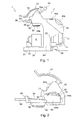
- FIG. 1 shows a side view of a beverage system 1 including a beverage preparation machine 2 according to the present invention.
- the machine 2 comprises a housing 2a containing at least a heater 10, a pump 20 and control means 30. Further the machine comprises a reservoir 40 connected to the machine, an extraction head 50 and a base portion 2b which is preferably provided with feet for positioning the machine on a support (e.g. table) in a stable manner.
- the machine further comprises a stand 2c for a receptacle R, such as a cup, having an upper surface 2d provided with a grid 2e on which the receptacle is positioned.
- the reservoir 40 supplies liquid such as water to the heater 10 and the pump 20, and hence to the extraction head 50 of the machine 2 through a liquid circulation system.
- the reservoir 40 is connected to the machine in a detachable manner and has an inlet 40a for introducing liquid. It is preferably provided with a handhold 40b for facilitating the handling of the reservoir 40. Thus a user handles the reservoir 40 in a convenient way.
- An outlet (not represented in the drawings) which is preferably situated at the bottom of the reservoir 40 provides a connection between the reservoir 40 and the machine 2.
- an external water supply may be provided.
- the extraction head 50 of the machine comprises a closing mechanism 52 for selectively enclosing an ingredient capsule 54 provided to the machine and a control lever 56 for selectively supplying either cold or hot water to the extraction head 50 and hence to the capsule 54.
- the control lever 56 is connected at least to the control means 30 of the machine 2.
- the control lever 56 may be switched over from a neutral position to a first position selecting hot water or to a second position selecting cold water. This selection may be easily achieved by moving the control lever 56 to the left or to the right when seen in front-rear direction of the machine 2. Accordingly, a user can decide and therefore select whether to supply cold or hot water to the capsule provided to the machine in order to prepare a cold or hot beverage.
- a capsule-holder 58 comprising holding means 60 for holding the ingredient capsule 54 is inserted into an aperture 62 of the extraction head 50 for being received in a receiving chamber 64 (not shown in Figure 1 ) of the extraction head 50.
- the capsule-holder is therefore releasably connected to the machine.
- the aperture 62 for accessing the receiving chamber 64 is located at the front side of the extraction head.
- the holding means 60 for receiving the capsule 54 are designed such that a beverage delivery portion 54a, e.g. an outlet port, of the capsule 54 is not enclosed in the holding means.
- a self-opening lower face opens in the capsule due to the pressure rise within the capsule 54 and hence supplies the beverage for example to the receptacle R placed below the capsule 54.
- a handhold 66 is connected to the capsule-holder 58 in order to enable a convenient handling of the capsule-holder 58.
- the capsule-holder 58 is fitted with a front cover 68, which covers the aperture 62 when the capsule-holder 58 is inserted into said aperture.
- the extraction head 50 comprises an injection member 70 and a support 80 connected therebetween, both being located inside the extraction head.
- the connection between injection member 70 and support 80 may be made in a known manner through a connection mechanism e.g. as described in EP 2 071 988 A1 which is hereby incorporated by reference.
- the closing mechanism 52 enables a relative movement between the support 80 and a rear wall 64a of the receiving chamber 64.
- the support 80 is connected from below to a dome-shaped member 50a of the extraction head.
- the closing mechanism 52 When the closing mechanism 52 is activated by a user and lowered, the support 80 is lowered from an elevated or high open position (illustrated in Figure 2 ) towards guiding recesses 64b provided inside the extraction head 50.
- Such guiding recesses 64b are designed to guide the capsule-holder when slidably inserted into the receiving chamber 64 and to hold said capsule-holder 58 in a correct position within the receiving chamber 64.
- the capsule 54 held by the capsule-holder 58 may be efficiently enclosed within the receiving chamber 64 thanks to the closing mechanism 52.
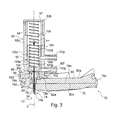
- Figure 3 illustrates an enlarged section view of injection member 70 and support 80 of Figure 2 .
- injection member 70 includes a piercing and injection unit 73 which has a piercing or puncturing member 74 for piercing or puncturing the ingredient capsule 54 (see Figure 2 ) as described in applicant's European patent EP 1 967 100 B1 .
- the member 74 is a needle made from stainless steel, or ceramic material.
- Piercing and injection unit 73 further has at least one inner through channel 75 which extends from an inlet orifice 75a, corresponding to one end 74a of the piercing member, to an outlet orifice 75b corresponding to the opposite end 74b which is designed to carry out the piercing or puncturing function.
- the channel is used for injecting a liquid that is supplied to the extraction head 50 by pump 20, such as water, into the ingredient capsule 54 after piercing.
- the liquid is introduced at the inlet orifice 75a and flows within the channel through to the outlet orifice 75b which is in communication with the interior of the capsule (not visible in Figure 3 ).
- Piercing and injection unit 73 such as described above is more specifically represented in Figures 4a and 4b and for example takes the form of a needle element.
- the needle element is preferably made of stainless steel. Needle element has been force-it into a traversing hole of a base plate 76 so as to be flush mounted on the upper horizontal face 76a of said base plate and protrude from the lower face 76b.
- injection unit 73 does not necessarily pierce an ingredient capsule but may fit through an aperture or an inlet port provided in the capsule.
- injection unit 73 which carries out the injection function only may take other forms.
- the capsule may be pierced by any other means and injection unit 73 which may here also take other forms only carries out the injection function.
- Base plate 76 is e.g. substantially disc-shaped.
- Base plate 76 has for example a substantially inverted U shape in the longitudinal cross-section illustrated in Figure 3 .
- the inverted U shape is defined by a peripheral surrounding edge 76c that delimits together with upper face 76a an inner recess.
- Support 80 includes a support plate which is located within into the inner recess.
- injection member may be made of a rubber-based material and molded onto support plate 80 (e.g. by injection molding).
- support plate 80 is located above base plate 76 and may be connected to the extraction head 50 of Figure 2 in a manner that is not represented in the drawings.
- Base plate 76 also includes a raising portion 76d axially extending along a longitudinal axis Z from upper face 76a, near the traversing hole where needle element 73 is engaged.
- Raising portion 76d further extends transversely from its upper end through a substantially ring-shaped extending portion 76e that is arranged concentrically around the longitudinal axis Z passing by the needle element traversing hole, at a distance from upper face 76a.
- Ring-shaped extending portion 76e is fixed at one end to raising portion 76d upper end and is free at its opposed end. Ring-shaped extending portion 76e has a tight-sealing function.
- the machine further includes a cleaning device 90 which is located facing the injection member 70 and the needle element.
- cleaning device 90 arranged is above the needle element and accommodated in a hollow casing 92 that is in contact with support plate 80. More particularly, the casing is secured to the upper face 80a of support plate 80 while lower face 80b thereof is in contact with upper face 76a of base plate 76.
- Casing 92 has a shape that is elongated along longitudinal axis Z and concentrically arranged around said axis Z passing by the needle element traversing hole.
- Casing 92 is substantially cylindrical in shape but other forms may be envisaged.
- Casing 92 has a body 92a surrounding an internal elongated cavity 94 that is open at one upper end 92b of the casing for inserting there through cleaning device 90.
- a closing member 97 e.g. a cap, is mounted in a secured and releasable manner on the upper end casing so as to close it temporarily.
- the casing has at one opposed lower end a small opening 92c compared to the large upper opening 92b.
- Casing 92 also has a base portion 92d which extends both axially and transversely from its body 92a, thereby forming a shoulder.
- the base portion shoulder is engaged under one or several resilient retaining members 96 which raise from the periphery of upper face 80a and inwardly project therefrom. Casing 92 is therefore firmly retained in position against upper face 80a.
- a central inner recess 92e is provided in base portion 92d from underneath.
- This recess is centred about the opening 92c and is in communication therewith.
- recess 92e fit with the outer dimensions of protruding portion 6e so that the latter may be tightly engaged or snapped into the recess.
- a plug member 98 is snapped or force-fit into the central aperture of ring-shaped protruding portion 76e from underneath.
- This plug member carries out a liquid-tight function and also has an inner through duct in its central portion. The inner through duct is aligned with the inner through channel 75 of needle element 73.
- a guiding member 99 is inserted into a hole which traverses support plate 80 in its whole thickness.
- Guiding member 99 has a through central duct which is in alignment with the inner through channel 75 of needle element 73 and inner through duct of plug member 98 when support plate 80 is accommodated within the base plate recess. Guiding member 99 is substantially cylindrical in shape for example.
- Casing 92 is also provided with at least one inlet opening enabling introduction of liquid under pressure into internal cavity 94.
- casing 92 is provided with two distinct inlet openings 92f and 92g which each take the form of ducts protruding outwardly from the wall constituting body 92a. The ducts 92f and 92g emerge through the wall into internal cavity 94.
- both ducts are located on the same side of the casing above the central portion of support plate 80 so as not to increase the overall size of the assembly (injection member 70 and support plate 80 with casing 92).
- one of the ducts is arranged above the other.
- One of the ducts is used for hot liquid (e.g. water) whereas the other is used for liquid (e.g. water) at ambient temperature.
- These ducts are in communication with pump 70 through a liquid circulation system.
- Cleaning device 90 includes a support member 100 that is movable along longitudinal axis Z between two main positions as schematically illustrated in Figure 4a and Figure 4 b. More particularly, support member is slidable within internal elongated cavity 94. Cleaning device 90 also includes an elongated cleaning member 102 that is connected to support member 100 and therefore moves with the latter.
- Elongated cleaning member 102 may be releasably connected to support member or permanently secured thereto by one end, the opposite end being free.
- Elongated cleaning member 102 may, for instance, take the form of a pin.
- Elongated cleaning member 102 has a shape and outer dimensions which respectively fit the shape and internal dimensions (e.g. internal diameter) of the inner channel 75.
- cleaning member 102 is able to follow a back and forth motion within channel 75 in the course of use of the machine for cleaning purpose.
- cleaning member 102 also respectively fit the shape and internal dimensions of plug member 98 and guiding member 99 so as to facilitate the sliding movement of cleaning member 102.
- guiding member 99 longitudinally guides cleaning member 102 during its sliding movement within channel 75.
- Support member 100 has a substantially cylindrical outer shape whose dimensions tightly fit the dimensions of internal cavity 94 for sliding purpose.
- Support member 100 includes a body portion 100a axially extending from a supporting element or base portion 100b that is transverse to the axial direction of extension and forms a closed end of the support member (lower end).
- the axial extension is along longitudinal axis Z which is vertical.
- longitudinal axis Z may be horizontal or inclined between horizontal and vertical directions.
- the elongated cleaning member 102 has an end that is secured to supporting element 100b. This end may be force-fit into a hole formed in supporting transverse element 100b.
- Body portion 100a radially or transversely extends at a distance from supporting transverse element 100b, while keeping on axially extending until reaching the opposed open end (upper end) of the support member.
- the radial or transverse extension forms a shoulder 100c (that is a transverse element) which therefore frees spacing 104 between the inner face of body wall 92a and the part of body portion 100a that is located below the shoulder.
- This part of body portion 100a has a narrower transverse dimension than shoulder 100c.
- spacing 104 takes the form of an annular cylindrical portion.
- This arrangement is made to ensure that liquid introduced through inlet duct 92g will always communicate with spacing 104 whatever the support member position.
- the elongated body portion 100a of support member is hollow and has an inner housing 100d.
- Inner housing 100d is bordered at one end (lower end) by the inner face 100e of supporting transverse element 100b and open at the opposite end (upper end) so as to be in communication with internal cavity 94.
- Housing 100d is for example cylindrically-shaped.
- the cleaning device 90 further includes active means which permanently exert a first predetermined force F1 on support member 100.
- This force F1 is exerted in a direction which is along longitudinal axis Z and here is downwardly oriented as illustrated in Figures 3 , 4a and 4b .
- the active means are preferably resilient means, such as spring means 106 in the drawings.
- other active means playing the same role may be alternatively used.
- pneumatic means or injection means which are suitable for injecting a fluid under pressure within housing 100d may be envisaged.
- Such a fluid may be water extracted from reservoir 40.
- spring means 106 are secured by one end to the inner face 100e and by the opposed end to the inner face of the closing member 97.
- the support member 100 is urged to occupy its lowest position (see also Figure 4b ), thereby urging elongated cleaning member 102 to be inserted into channel 75 for cleaning purpose (first active position).
- the length of cleaning member 102 has to be sized appropriately to be able to reach the outlet orifice 75b in Figures 3 and 4 b.
- the closing mechanism 52 of the extraction head 50 has to be brought into a closed position in order to lower the assembly comprising support 80 and injection member 70 and close the machine.
- the user then activates the machine by pressing an activation button or member and/or manipulating the control lever 56 and/or through any other activating or actuation means.
- Liquid e.g. water
- pump 20 which pumps liquid from the liquid source or reservoir 40. Liquid is thus brought to one of the two ducts 92f and 92g according to the user choice (hot or ambient temperature beverage).
- Liquid under pressure is then introduced into spacing 104 ( Figure 3 ) and fills it.
- spacing 104 When spacing 104 is thus filled and liquid keeps on flowing from the inlet duct, the pressure of the liquid within the spacing increases and, in particular, acts on the transverse element formed by shoulder 100c, thereby lifting support member 100.
- the liquid pressure is high enough to counteract the first predetermined force F1 and push support member 100 upwardly.
- liquid pressure acts both on outer face 100g and shoulder 100c and is schematically represented by the opposing force F2 (longitudinally directed). Force F2 is greater than force F1.
- liquid e.g. water
- cleaning member 102 comes into contact with the inner surface thereof and is thus able to remove any possible deposits, debris (e.g. scaling deposits) which may get accumulated inside the channel.
- debris e.g. scaling deposits
- cleaning member 102 has reached exit orifice 75b and will remain inside the channel until next operation of the machine. This provides an additional advantage in that no deposit can be formed within the channel due to the presence of cleaning member when the machine is at rest.
- support 80 has been schematically depicted by dotted lines for the sake of clarity.
- sealing means may be used in order to prevent any leakage of the liquid between the different parts of the assembly represented in Figure 3 .
- Figure 5 illustrates an enlarged partial section view of the interior of the extraction head 50 of Figure 2 , when the latter is in an open high position. In this position the beverage preparation machine is open for enabling an ingredient capsule to be introduced through the aperture 62 ( Figure 2 ).
- Figure 7 illustrates the closed position of the machine.
- the modified injection member 202 is connected to support 80 in the same manner as that described above for injection member 70 and support 80.
- Injection member includes a piercing and injection unit 204 which extends over the whole thickness of the assembled injection base plate 206 and support plate 80.
- Piercing and injection unit 204 has a piercing member 208 for piercing an ingredient capsule such as capsule 54 in Figure 2 .
- the function of the piercing member 208 is to form a hole or aperture (or several ones) in a wall of the capsule so that this hole will enable injection of liquid into said capsule.
- This hole or aperture (or these holes) may be formed by any other means such as puncturing, tearing means or the like (these remarks also apply to the embodiment described with reference to Figures 1 to 4b ).
- the unit 204 may alternately not necessarily be used to form a hole or aperture into an ingredient capsule but may fit through a hole or aperture or an inlet port already provided for in said capsule.
- injection unit 204 which carries out the injection function only may take other forms (conduit, pipe, nozzle, etc).
- the capsule may be pierced, punctured, torn, etc. by any other distinct means and injection unit 204 which may here also take other forms only performs the injection function.
- Piercing and injection unit 204 also has at least one inner through channel 210 which is used for injecting a liquid that is supplied to the extraction head 50 by pump 20 into the ingredient capsule after piercing.
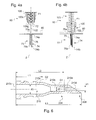
- Figure 6 represents in detail a cross-section of unit 204 which, here, for example takes the form of a needle element.
- unit 204 (needle element) comprises three channel portions 210a-c which break up channel 210 into:
- the outer diameter D1 of unit 204 proximate its free emerging end is small enough and the length of this member over which this diameter is kept is long enough to efficiently form a hole or aperture in the wall of an ingredient capsule through piercing, puncturing, or the like. If there was no second intermediary channel portion and just the third channel portion the outer diameter of the piercing member would be equal to D2 at the upstream end of the first channel portion. This would result in a less efficient piercing member. However, the second intermediary channel portion might be omitted. In this case, the part of the piercing member with outer diameter equal to D2 would be longer or, alternately, the length of first channel portion 210a would be longer so as to keep the same length of piercing member with an outer diameter of D1.
- inner diameters d1, d2 and d3 may respectively be equal to 0.6, 0.8 and 1.8mm, D1 is equal to 1.5mm and D2 to 2.6, the length L1 of third channel portion 210c is equal to 5mm, and the lengths L2 and L3 are respectively of 8.9 and 12mm.
- Needle element 204 is preferably made of stainless steel.
- the part of the piercing member with enlarged outer diameter D2 is rigid enough to be inserted into a through hole provided in support plate 80 of Figures 5 and 7 .
- the protruding elements arranged on the outer surface of the piercing member will serve as retaining elements.
- piercing and injection unit 204 represented in Figure 6 may be used in any other kind of beverage preparation machine where a hole or an aperture has to be formed in an ingredient capsule (e.g. in a wall thereof) and liquid has to be injected therethrough.
- the machine illustrated in Figures 1 and 2 is particularly suitable for including such a piercing and injection unit in a releasable connection or not.
- the machine 200 further comprises a cleaning device 220 facing the injection member 202 and unit 204 and located above them.
- cleaning device 220 is accommodated in a hollow casing 222 which is maintained in contact with the upper face 80a of support plate 80 through maintaining means.
- shoulders 222a and 222b formed on the outer surface of casing 222 cooperate with structural means of the extraction head 50 for maintaining casing 222 in position.
- Casing 222 has a shape that is elongated along a longitudinal axis and concentrically arranged around said axis passing by the needle element traversing hole.
- Casing 222 is substantially cylindrical in shape but other forms may be envisaged.
- Casing 222 has a body 222a surrounding an internal elongated cavity 224 that is open at one upper end 222b of the casing for inserting therethrough cleaning device 220.
- Casing 222 has at its lower end a base portion 222c.
- a central through hole 222d ( Figure 7 ) is formed in the base portion so as to permit communication between the extension of the casing and internal cavity 224.
- An annular recess 222e is provided in base portion 222c from underneath and surrounds hole 222d.
- Annular recess 22e e.g. in the shape of an annular cylindrical portion, accommodates protruding portion 76e (ring-shaped portion) of Figure 3 which has a tight-sealing function.
- Through hole 222d is aligned with the inner through channel 210 of needle element 204.
- Casing 222 is also provided with at least one inlet opening enabling introduction of liquid under pressure into internal cavity 224.
- casing 222 is provided with two distinct inlet openings 222f and 222g which each take the form of ducts protruding outwardly from the wall constituting body 222a. The ducts 222f and 222g emerge through the wall into internal cavity 224.
- both ducts are located on the same side of the casing above the central portion of support plate 80 so as not to increase the overall size of the assembly (injection member 202 and casing 222 enclosing the cleaning device).
- one of the ducts is arranged above the other.
- One of the ducts is used for hot liquid (e.g. water) whereas the other is used for liquid (e.g. water) at ambient temperature.
- These ducts are in communication with pump 20 ( Figure 1 ) through a liquid circulation system including e.g. flexible pipes.
- Cleaning device 220 includes a support member 226 that is movable along the longitudinal axis of the casing 222 between two main positions as schematically illustrated in Figure 5 and Figure 7 . More particularly, support member 226 is slidable within internal elongated cavity 224 through a guiding member 228.
- the latter has, for instance a ring shape with a central hole for being mounted around the longitudinally-shaped support member 226.
- Guiding member 228 is provided with traversing holes enabling passage of liquid therethrough.
- guiding member is adjusted around support member 226 in a zone where the support member has a shoulder due to a reduced section. The external diameter of guiding member 228 fit the dimensions of internal cavity for sliding purpose.
- Support member 226 protrudes from casing 222 at its upper end.
- a closing member 230 closes the open upper end of casing 222 and is provided with a central inner hole for receiving therein support member 226 and enabling sliding movement of the latter therethrough.
- the closing member is e.g. a flange with an inner peripheral seal (e.g. an O-ring, Quad-ring, Double Delta seal, etc) in contact with support member 226.
- the closing member is mounted on the casing in a secured and releasable known manner.
- Cleaning device 220 also includes an elongated cleaning member 232 that is connected to support member 226 and therefore moves with the latter.
- Elongated cleaning member 232 may be releasably connected to an end of the support member or permanently secured thereto by one end, the opposite elongated cleaning member end being free.
- member 232 is connected to an end of support member 226 which has a reduced section. This reduced section portion fits the dimensions of through hole 222d ( Figure 7 ).
- Support member 226 and elongated cleaning member 232 are in alignment.
- Elongated cleaning member 232 may, for instance, take the form of a pin.
- Elongated cleaning member 232 has a shape and outer dimensions (outside diameter of e.g. 0.5 mm) which respectively fit the shape and internal dimensions (e.g. internal diameter(s)) of the inner through channel 210 and, in particular, of the smallest channel portion thereof.
- cleaning member 232 is able to follow a back and forth motion within channel 210, in particular, first channel portion 210a, in the course of use of the machine for cleaning purpose.
- the support member 226 has two opposed ends: one end 226a is connected to elongated cleaning member 232 while the other opposed end 226b is connected to a fixed part of the machine through a linking mechanism.
- the opposed end 226b is connected to a shaft 234 (or pin member) which is freely mounted in translation within guiding means 236 such as a rail member or slot.
- the guiding means are closed or equipped with two stops at their two opposed ends which define the ends of the path travelled by shaft 234.
- guiding member 236 is inclined with respect to horizontal and vertical lines so as to be adapted to follow the substantially circular (along a portion of a circle) downward movement of the injection unit.
- the opposed end 236b is freely rotatably mounted in rotation about shaft 234 that is arranged perpendicularly to support member 226 and slidably engages guiding member 236.
- Guiding means 236 are provided in a carrier 238 which is fixedly connected to the chassis of the beverage preparation machine.
- carrier 238 may take the form of an inverted U with the horizontal part being represented in cross-section in the drawings and the two vertical descending arms which are fixed to the chassis being hidden.
- Guiding means 236 are for example made integral with the horizontal part of carrier 238.
- the extraction head 50 including the assembly comprising the injection unit and the cleaning device is in a high position waiting for introduction of an ingredient capsule into the machine.
- the support member 226 is in a lower position (guiding member 228 rests against the bottom of internal cavity 224) and the elongated cleaning member is fully inserted into channel 210 so that its extremity 232a extends through the free emerging end 210d of the channel (first active position of elongated cleaning member).
- the shaft 234 is arranged at one end of guiding means 236, in the upper part thereof, and in contact with a stop end of guiding means.
- the machine When an ingredient capsule has been introduced in the machine by a user, the machine can be closed ( Figure 1 position). More particularly, closing of the machine is obtained through actuating the closing mechanism 52 from position represented in Figure 2 (and Figure 5 ) to Figure 1 position (and Figure 7 ).
- shaft 234 slides into guiding member 236 (e.g. rail member or slot) down to the opposite stop end thereof.
- guiding member 236 e.g. rail member or slot
- This arrangement acts as retaining means for retaining the support member 226, while the injection unit (more particularly, the injection member 202, support 80 and casing 222) keeps on moving downwardly to reach the closed position in Figure 7 .
- member 232 is withdrawn from first and second channel portions 210a and 210b so that its free extremity is located in the third channel portion (second rest position). This makes it possible in this position for liquid to be successively introduced through one of the ducts 222f and 222g, internal cavity 224, through hole 222d and inner channel portions 210c, 210b, and 210a before exiting through outlet orifice 210a under the form of a jet. The jet is injected into the ingredient capsule.
- this reduced path which corresponds to the path travelled by shaft 234 within guiding means 236 can be easily housed in the machine without modifying the external size thereof.
- the elongated cleaning member 232 slides within channel 210 and, in particular, within first channel portion 210a which is the most susceptible of being clogged by debris, deposits such as scaling deposits.
- the sliding movement enables removal of any deposits that may get accumulated on the inner surface of the wall defining the channel portion.
- the ingredient capsule 54 contains food ingredients or substances that are used by addition of a liquid, e.g. water, for preparing a beverage or, to a larger extent, liquid comestibles.
- a liquid e.g. water
- Such ingredients may be coffee, e.g. roasted and grounded coffee.
- ingredients include, in a non limitative way, tea (leaf tea, herbal tea or fruit tea), soluble tea or soluble coffee, a mixture of ground coffee and soluble coffee, cocoa, or a cocoa or chocolate-based or supplemented product including coffee, a soup, or foods such as in the form of infusions, for example.
- any ingredient capsule may be used and for instance open capsules such as filter pods or the like.
- an injection member having more than one needle element which may be connected by a means of a duct or the like.
- the pattern and design of these needle elements may vary in order to meet different requirements regarding the injection conditions of the beverages to be prepared.
- the injection conditions may vary especially with regard to the dissolution and/or extraction of the substances provided within the ingredient capsules 54.
Abstract
The invention concerns a beverage preparation system (1) for preparing a beverage by injection of a liquid into an ingredient capsule, the beverage system comprising an ingredient capsule (54) and a beverage preparation machine (2; 200) having:
- an injection unit (73; 204)with at least one inner through channel (75; 210) for injecting a liquid into the ingredient capsule;
- operating means for causing the machine to prepare a beverage, characterized in that the machine further comprises a cleaning device (90; 220) for automatically cleaning said at least one inner through channel, said cleaning device being actuated by said operating means.
Description
- The present invention concerns a beverage system including a beverage preparation machine for preparing a beverage by injection of a liquid into an ingredient capsule.
- An ingredient capsule contains food ingredients or substances that are used by addition of a liquid for preparing a beverage or, to a larger extent, liquid comestibles.
- A beverage preparation machine comprises a receptacle for accommodating a capsule and a fluid injection system for injecting a fluid, preferably a liquid such as water, under pressure into said capsule. For instance, water injected under pressure in the capsule, for the preparation of a coffee beverage, is preferably hot, that is to say at a temperature above 70°C. However, in some particular instances, water might also be at ambient temperature. The pressure inside the capsule during extraction and/or dissolution of the capsule ingredient(s) is typically about 1 to 6 bar for dissolution products, and 2 to 12 bar for extraction of roasted and grounded coffee. Such a preparation process greatly differs from the so-called "brewing" process of beverage preparation - particularly for tea and coffee, in that brewing requires a long time of infusion of the ingredient(s) by a fluid (e.g. hot water), whereas the beverage preparation process allows a consumer to prepare a beverage, for example coffee, within a few seconds.
- The principle of extracting and/or dissolving the ingredient(s) of a closed capsule under pressure is known and consists typically of inserting the capsule into a receptacle of a machine, injecting a quantity of pressurized water into the capsule, so as to create a pressurized environment inside the capsule either to extract the ingredient(s) or dissolve it, and then release the extracted ingredient(s) or the dissolved ingredient(s) through the capsule. Capsules of this type have already been described for example in the Applicant's
European patents 1 472 156 B1 , and1 784 344 B1 . - Machines operating in accordance with this principle have already been described for example in documents
CH 605 293 EP 242 556 - When the beverage to be prepared is coffee, a capsule may contain roast and ground coffee powder as an ingredient, which is to be extracted thanks to hot water injected therein.
- Capsules have been developed for such an application, which are disclosed in the Applicant's
European patent EP 1 784 344 B1 , and Europeanpatent application EP 2 062831 . - In short, a capsule of this type typically comprises:
- a hollow body and an injection wall which is impermeable to liquids and to air and which is attached to the body at the top end of the capsule and adapted to be punctured by e.g. an injection needle of the machine;
- a chamber containing a bed of roast and ground coffee to be extracted;
- an aluminium membrane disposed at the bottom end of the capsule for closing said capsule and maintaining the internal pressure within the chamber, said membrane being associated with perforating means for forming dispensing holes in the membrane when said internal pressure within the chamber reaches a certain predetermined value,
- optionally, means configured to break the jet of water so as to reduce the speed of the jet of water injected into the capsule and distribute water across the bed of substance at a reduced speed.
- As the beverage preparation machine of the above-described kind uses water as extraction fluid scaling deposits are formed in the parts of the machine which are in contact with water that is the water circulation system.
- These scaling deposits get accumulated in the parts of the water circulation system over time along with the use of the machine.
- This may lead through inlet channel of the needle that is used for injecting water into the pierced capsule to be clogged with time.
- Users of these machines are asked to regularly clean the water circulation system with a descaling or anti-scaling product in order to avoid clogging of the system and in particular of the needle.
- However, as the diameter of the channel internal to the needle is narrow it is particularly favourable to scaling.
- In order to deal with this problem the existing machines are equipped with a cleaning tool which takes the form of a pin-shaped member.
- This pin-shaped member has an outside diameter which corresponds to the internal diameter of the needle channel taking account of the mechanical tolerance.
- Machines' user guide provides consumers with instructions as to how regularly use this cleaning tool in order to avoid scaling and therefore subsequent clogging of the machines.
- Users are instructed to introduce the pin-shaped member into the needle channel by an end thereof (the end by which water is supplied to the channel) through the opposite end in order to rub the inner wall of the channel and therefore remove any scaling deposits.
- Although technically satisfactory, such a manual operation requires the user to regularly plan the cleaning, which is not satisfactory. Furthermore, in case the user omits the regular descaling maintenance, this may result in clogging of the needle, such that it then necessitates to send the machine to an after-sales service, which is of course undesirable.
- According to a first aspect, the invention concerns a beverage preparation system for preparing a beverage by injection of a liquid into an ingredient capsule, the beverage system comprising an ingredient capsule and a beverage preparation machine having:
- an injection unit with at least one inner through channel for injecting a liquid into the ingredient capsule;
- operating means for causing the machine to prepare a beverage, characterized in that the machine further comprises a cleaning device for automatically cleaning said at least one inner through channel, said cleaning device being actuated by said operating means.
- The system is conceived so that cleaning of the at least one inner through channel is automatically operated, i.e. without any human intervention dedicated to cleaning.
- The only human intervention is that one necessary for operating the beverage preparation machine with a view to preparing a beverage.
- It is to be noted that cleaning the at least one inner through channel means cleaning the internal surface of the wall that delimits the inner through channel and on which deposits may get accumulated.
- According to one feature, the cleaning device has an elongated cleaning member, actuation of said cleaning device causing said elongated cleaning member to slide within the at least one inner through channel. The sliding movement of the elongated cleaning member within the at least one inner through channel makes it possible to remove any deposits that may get accumulated on the internal surface of the wall surrounding said channel.
- Thus, the cleaning operation is automatically triggered when operating means for causing the beverage preparation machine to prepare a beverage are actuated.
- The present invention suppresses human intervention for cleaning the injection unit and, therefore, makes cleaning more regular and more reliable than in the past.
- Furthermore, the cleaning device does not use any additional energy source for being operated.
- In addition, the cleaning device does not modify the current operation of the beverage preparation machine for preparing beverages. It is just easily and conveniently interfaced with the current mechanism of the machine.
- It is to be noted that the injection unit may be traversed by several inner channels and, correspondingly, the cleaning device may include several elongated cleaning members each being intended to be inserted in a channel for cleaning thereof.
- According to one feature, the elongated cleaning member is able to automatically occupy two positions, a first active position in which said elongated cleaning member extends within the at least one inner through channel through to the free emerging end thereof, and a second rest position in which said elongated cleaning member is at least partly withdrawn from said at least one inner through channel.
- Thus, actuation of the cleaning device causes the elongated cleaning member to occupy either of the two positions depending on the position of said elongated cleaning member when starting actuation of the cleaning device.
- For instance, before actuating the operating means of the machine the elongated cleaning member may be in the first active position and will move to the second rest position upon actuation of said operating means.
- Alternatively, the starting position of the elongated cleaning member may be the second rest position before actuating the operating means.
- According to one feature, the at least one inner through channel comprises at least two channel portions, a first channel portion including the free emerging end of said at least one inner through channel and having a first inner diameter, and at least one upstream channel portion disposed upstream said first channel portion and having an enlarged second inner diameter. The first channel portion has preferably a reduced diameter which is suitable for producing a jet of liquid when exiting the free emerging end of the channel.
- In order to avoid increasing the risks of scaling deposits formation within the channel the upstream channel portion (e.g. second channel portion) has preferably an enlarged inner diameter.
- According to another feature, the at least one inner through channel may further comprise a third channel portion disposed upstream a second channel portion and having an enlarged third inner diameter.
- It is to be noted that the length of the first channel portion must be sufficient to produce a jet of liquid but must not be too long in order to avoid augmenting the risks of scaling deposits accumulation inside.
- Having three different channel portions with three successive different inner diameters instead of one may be useful to avoid a sharp increase in inner diameter within the channel.
- Also, this intermediary channel portion of intermediary diameter makes it possible to have a thinner outer size for the injection unit close to the free emerging end of the channel, which is more favourable to the piercing (or puncturing or tearing, etc) of an ingredient capsule.
- This is because having only two channel portions will render the outer size of the injection unit proximate the free emerging end of the channel wider and, therefore, less favourable to the piercing operation.
- According to another feature, the elongated cleaning member has a free extremity which, in the second rest position, is located in the at least upstream channel portion (e.g. a second channel portion).
- Alternatively, in case the at least one inner through channel has three channel portions, then the free extremity of the elongated cleaning member may be, in the second rest position, located in the third channel portion.
- When the free extremity of the elongated cleaning member is located in the upstream channel portion (either the second or the third one) this leaves sufficient room between said elongated cleaning member and the surrounding wall of the channel portion to enable circulation of liquid therebetween as well as in the first channel portion.
- Thus, partly withdrawing the elongated cleaning member from the inner through channel (the elongated cleaning member is fully withdrawn from the first channel portion) makes it possible to enable circulation of liquid within the whole channel through to the free emerging end thereof for being injected into an ingredient capsule.
- According to another feature, the elongated cleaning member has an outside diameter which substantially fits the first inner diameter of the first channel portion while enabling sliding of said elongated cleaning member thereinto.
- Thus, the transverse dimension of the elongated cleaning member (e.g. its diameter) is adjusted to the first inner diameter of the first channel portion for efficiently cleaning the surface of the internal wall defining this channel portion thanks to a sliding movement within said channel portion.
- In the configuration of an inner through channel broken up into several channel portions, the risks of clogging of the channel portions may arise, in particular, in the portion of reduced diameter, that is the first channel portion.
- The other upstream located channel portions are less prone to clogging.
- According to a first embodiment, said operating means comprise actuation means for actuating the machine from a first open position in which said machine is open for enabling introduction of the ingredient capsule thereinto to a second closed position in which said machine is closed and the ingredient capsule is inside said machine for liquid injection, and vice versa, said cleaning device being actuated by said actuation means. Thus, the mere actuation of the opening/closing mechanism of the beverage preparation machine makes it possible to actuate the cleaning device and, therefore, the cleaning operation associated therewith.
- According to this embodiment, cleaning takes place when opening the machine for introducing an ingredient capsule thereinto and after the beverage has been prepared, when opening the machine again for removing the used ingredient capsule.
- Thus, cleaning takes place twice every cycle of use of the beverage preparation machine.
- This embodiment is advantageous in that cleaning is merely triggered when opening and/or closing the machine.
- As an example, in the first open position of the machine the injection unit may be in a high position and in the second closed position the injection unit may be in a low position.
- The injection unit is therefore moved from a high to a low position when closing the machine or from a low to a high position when opening the latter.
- According to another feature, the elongated cleaning member and the injection unit are movable relative to one another when the machine is actuated from the first open position to the second closed position and vice versa. Thus, when actuating the machine from one position to the other position the elongated cleaning member and the injection unit are movable relative to one another so that the elongated cleaning member may slide within the at least one inner through channel.
- Furthermore, it is to be noted that the elongated cleaning member and the injection unit are connected to a part of the beverage preparation machine (e.g. the extraction head) which is movable between the first open position and the second closed position.
- According to one feature depending from the latter feature, the cleaning device has a support member to which the elongated cleaning member is connected, said support member being movable relative to the injection unit over a reduced path so that the elongated cleaning member is only withdrawn in part from said at least one inner through channel in its second position.
- This arrangement is advantageous in that a small displacement of the support member and the elongated cleaning member with respect to the injection unit is sufficient to enable efficient cleaning of the at least one inner through channel through a sliding movement.
- Such a reduced displacement necessitates fewer space, which, therefore, does not enlarge the outer dimensions of the machine.
- More particularly, this arrangement is made possible since in the second position of the elongated cleaning member its free extremity is located in an upstream channel portion enabling passage of liquid through to the free emerging end of the inner through channel and, therefore, injection of said liquid into the ingredient capsule.
- According to another feature, the support member has two opposed ends, one end being connected to the elongated cleaning member and the other opposed end being linked with guiding means which are connected to the machine, said other opposed end being slidably guided over said reduced path when the machine is actuated from the first open position to the second closed position, and vice versa.
- The support member is therefore guided by its opposed end over a reduced path which is defined by two stops which are disposed at the opposed ends of a guiding rail or slot.
- According to another embodiment, the beverage preparation machine has:
- a liquid source
- a pump for pumping said liquid from said liquid source towards the injection unit,
- activating means for causing said liquid to be pumped from said source towards said injection unit, said cleaning device being actuated by said activating means.
- Thus, cleaning may automatically take place based on the actuation by liquid pumped from the liquid source towards the injection unit.
- This self-cleaning operation is made possible every cycle of beverage preparation by use of the pressure of the liquid that is pumped and injected into the capsule.
- The injection of liquid through the at least one inner channel into the capsule makes it possible to move back the elongated cleaning member from its first active position to its second rest position.
- When liquid is no longer injected into the capsule and therefore the liquid pressure is very low, the elongated cleaning member is then automatically urged to be more deeply re-inserted into the at least one inner through channel without any human intervention.
- This reciprocating motion of the elongated cleaning member enables rubbing of the inner surface of the wall of the at least one inner channel and, therefore, removal of any deposits (e.g. scaling deposits when the liquid is water) that may get accumulated on the surface of the wall.
- As has already been mentioned above, the transverse dimension of the elongated cleaning member (e.g. a pin) roughly corresponds to the inner diameter of the at least one inner through channel in its narrower portion taking account of the mechanical clearance.
- According to an embodiment, the injection unit is a piercing and injection unit that includes a piercing or puncturing member for piercing or puncturing an ingredient capsule, the at least one inner through channel being formed in said piercing or puncturing member. Liquid is therefore injected into the capsule after piercing or puncturing thereof.
- According to one feature, the elongated cleaning member is able to automatically occupy said two positions depending on the injection or not of liquid into the at least one inner through channel, said elongated cleaning member being in said first active position in the absence of liquid injection thereinto, said elongated cleaning member being in said second active position due to the pressure of liquid injected into the at least one inner through channel. The elongated cleaning member is in either position according to the actuation of liquid injection or not.
- According to one feature, the cleaning device includes active means for exerting upon the elongated cleaning a first predetermined force (F1) so as to urge said elongated cleaning member to be inserted into the at least one inner through channel with a view to occupying the first active position.
- These active means, e.g. resilient means, are permanently integrated in the machine so as to permanently exert the first predetermined force on the elongated cleaning member whatever the status of operation of the liquid injection process, thereby meaning that the liquid may be in the course of injection or not.
- In contrast, the liquid pressure does not always act on the elongated cleaning member.
- Thus, the elongated cleaning member tends to be inserted into the at least one inner through channel out of mere conception of the cleaning device.
- According to one feature, the elongated cleaning member is able to be pushed backwards under the action of the pressure of the liquid to be injected into the at least one inner through channel and which counteracts the first predetermined force so that the elongated cleaning member is at least partly withdrawn from said at least one inner through channel.
- Thus, when the liquid is circulated under pressure within the liquid circulation system of the machine, e.g. thanks to a pump, and brought near the inlet of the at least one inner through channel, the liquid pressure acts on the cleaning device member (e.g. to which the elongated cleaning member is connected) to counteract the first predetermined force and push back the elongated cleaning member to its rest position.
- More particularly, the liquid pressure applies a second force to the cleaning device that is greater in intensity than the first one and opposed in direction.
- According to one feature, the cleaning device comprises a support member to which the elongated cleaning member is connected.
- According to one feature, the support member has a substantially cylindrical shape that is elongated along a longitudinal axis (Z), the support member being closed at one end by a transverse element, the elongated cleaning member being connected to said transverse element and extending therefrom outwards.
- The shape of the support member is particularly simple.
- The elongated cleaning member may releasably be connected to the support member or be an integral part thereof.
- According to one feature, the support member is open at the opposed end and has an inner housing in communication with the open end for receiving active means.
- The cleaning device thus configured is compact.
- The active means may be partially or fully received within the housing.
- According to another feature, the beverage preparation machine includes a hollow elongated casing for accommodating therein the cleaning device, said cleaning device being slidable within the casing for occupying the two positions, said casing having at least one inlet opening and at least one outlet opening, said at least one inlet opening enabling liquid to be introduced in the casing before being injected into the at least one inner through channel through at least one outlet opening.
- The cleaning device is thus protected within the casing.
- The cleaning device and the at least one inlet opening are configured so that liquid under pressure may be introduced into the casing through said at least one inlet opening and applied against a surface of the support member with a view to longitudinally sliding it within the casing from its active to its rest position, thereby freeing the at least one inner through channel.
- According to one feature, the beverage preparation machine includes a capsule-holder for holding the ingredient capsule.
- According to one feature, the capsule-holder is in a releasable connection with the beverage preparation machine.
- The ingredient capsule may be placed in the capsule-holder before introducing the latter in the machine.
- Alternatively, the capsule-holder may be located within the machine and the ingredient capsule is introduced in the machine either directly into the capsule-holder or indirectly, that is the capsule-holder is moved from a first position to a second position to engage with the introduced capsule upon activation of a mechanism.
- According to a second aspect, the invention concerns a cleaning device that is intended to be integrated in a beverage system of the above described type.
- More particularly, the invention concerns an assembly comprising a channel in which a liquid temporarily flows and a cleaning device for cleaning said channel, said cleaning device including :
- a support member;
- an elongated cleaning member connected to the support member and that is suitable for being inserted into the channel for cleaning thereof;
- said support member and elongated cleaning member being movable in a forward direction under the action of a predetermined force so as to be urged to occupy a first active position in which said elongated cleaning member extends within the channel through to the free emerging end thereof, said support member and elongated cleaning member being movable in a backward direction under the action of an opposed predetermined force so as to be urged to occupy a second rest position in which said elongated cleaning member is at least partly withdrawn from said channel.
- The invention also concerns a cleaning device for cleaning a channel in which a liquid temporarily flows, said cleaning device including:
- a support member;
- an elongated cleaning member connected to the support member and that is suitable for being inserted into the channel for cleaning thereof; said support member and elongated cleaning member being movable in a forward direction under the action of a predetermined force so as to be urged to occupy a first active position in which said elongated cleaning member extends within the channel through to the free emerging end thereof, said support member and elongated cleaning member being movable in a backward direction under the action of an opposed predetermined force so as to be urged to occupy a second rest position in which said elongated cleaning member is at least partly withdrawn from said channel.
- According to another feature, the cleaning device, either of the assembly or alone, includes active means for exerting upon the support member a first predetermined force urging the elongated cleaning member to occupy the first active position in the absence of liquid within the channel, whereas said elongated cleaning member is urged to be at least partly withdrawn from the channel under the action of a second greater opposing predetermined force resulting from the pressure of a liquid to be injected into the channel and acting on the support member.
- Such a cleaning device is able to occupy two distinct positions depending on the injection of liquid into the channel or not.
- For example, the first force is along a longitudinal axis as well as the second force.
- According to one feature, the active means are resilient means, e.g. spring means.
- The support member may therefore be resiliently mounted, e.g. spring-mounted.
- According to one feature, the support member has a substantially cylindrical shape that is elongated along a longitudinal axis (Z), the support member being closed at one end by a transverse element, the elongated cleaning member being connected to said transverse element and extending therefrom outwards.
- According to one feature, the transverse element has two opposite faces, an inner face being disposed inside the support member and submitted to the action of the first predetermined force (F1) exerted by the active means, and an outer face being disposed outside the support member and submitted to the second greater opposing predetermined force (F2) when liquid is injected into the channel.
- According to a third aspect, the invention concerns a method for preparing a beverage with a beverage preparation machine by injection of a liquid into an ingredient capsule, said machine comprising an injection unit with at least one inner through channel for injecting a liquid into the ingredient capsule, the method including the steps of:
- providing an ingredient capsule;
- operating the machine for causing said machine to prepare a beverage, characterized in that said method further comprises the step of cleaning the at least one inner through channel, said cleaning step being automatically initiated when the operating step for operating the machine is performed.
- Thus, automatic cleaning is operated at every cycle of normal use of the machine, i.e. without any specific human intervention for cleaning purpose.
- When a user decides to operate the beverage preparation machine for preparing a beverage cleaning is automatically initiated.
- In a non limitative way, operating the machine may comprise two steps or actions.
- According to a first step or action, said operating step for operating the machine includes an actuating step for actuating the machine from a first open position in which said machine is open for enabling introduction of the ingredient capsule thereinto to a second closed position in which said machine is closed and the ingredient capsule is inside said machine for liquid injection, and vice versa.
- As has already been mentioned above, opening or closing the beverage preparation machine triggers the cleaning operation for cleaning the at least one inner through channel of the injection unit.
- Thus, cleaning takes place every time the machine moves from the first position to a second position, and vice versa.
- Also, the machine comprises a liquid source and a pump, the method further includes a step of injecting liquid into the ingredient capsule through said at least one inner through channel, said automatically cleaning step being performed before and/or during and/or after the injection of liquid. Thus, cleaning may occur in an automated manner at any time in relation to the injection of liquid, that is before and/or during and/or after the injection of liquid.
- Operating the machine for preparing a beverage may also comprise a second step or action of activating pumping of liquid for causing said liquid to be pumped from said liquid source towards the injection unit, said automatically cleaning step being performed when said activating step is performed.
- This activation of the machine takes place after the machine has been actuated, i.e. moved from a closed position to an open position for inserting an ingredient capsule thereinto and then from said open position to a closed position.
- If the machine is already open, actuation of the machine means moving the latter from its open to a closed position after inserting an ingredient capsule.
- Here, the user activates the preparation of a beverage by activating a mechanism (e.g. he/she may press a button, handle a lever, etc.).
- The cleaning is performed using the cycle of injection of liquid into a capsule and the following cycle where injection stops (and pressure of the liquid decreases down to zero).
- In an embodiment, the method further includes piercing or puncturing the ingredient capsule with a piercing or puncturing member, said at least one inner through channel being formed within said piercing or puncturing member.
- The principle, here, is to form an aperture or an hole (or several ones) into the closed ingredient capsule (e.g. in a wall closing the capsule) whatever the means used for.
- The injection is then made into the pierced or punctured ingredient capsule through the formed aperture or hole.
- Additional features and advantages of the present invention are described in, and will be apparent from, the description of the presently preferred embodiments which are set out below with reference to the drawings in which:
-
Figure 1 is a schematic side view of a beverage system and beverage preparation machine according to an embodiment of the invention; -
Figure 2 is a schematic side view of the extraction head ofFigure 1 with a capsule held by a capsule-holder before being inserted into the extraction head; -
Figure 3 is a schematic cross-section of an assembly according to the invention that is part of the extraction head ofFigure 2 ; -
Figures 4a and 4b are two schematic views of two respective positions of a cleaning device according to the invention and that is represented inFigure 3 ; -
Figure 6 is a schematic view of a needle element; -
Figures 5 and 7 are respectively schematic views of the extraction head of a beverage preparation machine according to another embodiment of the invention in an open and a closed position. -
Figure 1 shows a side view of abeverage system 1 including abeverage preparation machine 2 according to the present invention. Themachine 2 comprises ahousing 2a containing at least aheater 10, apump 20 and control means 30. Further the machine comprises areservoir 40 connected to the machine, anextraction head 50 and abase portion 2b which is preferably provided with feet for positioning the machine on a support (e.g. table) in a stable manner. The machine further comprises astand 2c for a receptacle R, such as a cup, having anupper surface 2d provided with agrid 2e on which the receptacle is positioned. Thereservoir 40 supplies liquid such as water to theheater 10 and thepump 20, and hence to theextraction head 50 of themachine 2 through a liquid circulation system. Preferably, thereservoir 40 is connected to the machine in a detachable manner and has aninlet 40a for introducing liquid. It is preferably provided with ahandhold 40b for facilitating the handling of thereservoir 40. Thus a user handles thereservoir 40 in a convenient way. An outlet (not represented in the drawings) which is preferably situated at the bottom of thereservoir 40 provides a connection between thereservoir 40 and themachine 2. - It is to be noted that, in addition to the
integrated reservoir 40 or as an alternative, an external water supply may be provided. - The
extraction head 50 of the machine comprises aclosing mechanism 52 for selectively enclosing aningredient capsule 54 provided to the machine and acontrol lever 56 for selectively supplying either cold or hot water to theextraction head 50 and hence to thecapsule 54. In this connection, thecontrol lever 56 is connected at least to the control means 30 of themachine 2. Hence, thecontrol lever 56 may be switched over from a neutral position to a first position selecting hot water or to a second position selecting cold water. This selection may be easily achieved by moving thecontrol lever 56 to the left or to the right when seen in front-rear direction of themachine 2. Accordingly, a user can decide and therefore select whether to supply cold or hot water to the capsule provided to the machine in order to prepare a cold or hot beverage. - As can be seen in
Figure 1 , a capsule-holder 58 comprising holding means 60 for holding theingredient capsule 54 is inserted into anaperture 62 of theextraction head 50 for being received in a receiving chamber 64 (not shown inFigure 1 ) of theextraction head 50. The capsule-holder is therefore releasably connected to the machine. Theaperture 62 for accessing the receivingchamber 64 is located at the front side of the extraction head. The holding means 60 for receiving thecapsule 54 are designed such that abeverage delivery portion 54a, e.g. an outlet port, of thecapsule 54 is not enclosed in the holding means. - When introducing liquid into the
capsule 54, a self-opening lower face opens in the capsule due to the pressure rise within thecapsule 54 and hence supplies the beverage for example to the receptacle R placed below thecapsule 54. Furthermore, ahandhold 66 is connected to the capsule-holder 58 in order to enable a convenient handling of the capsule-holder 58. Furthermore, the capsule-holder 58 is fitted with afront cover 68, which covers theaperture 62 when the capsule-holder 58 is inserted into said aperture. - As schematically illustrated in
Figure 2 , theextraction head 50 comprises aninjection member 70 and asupport 80 connected therebetween, both being located inside the extraction head. The connection betweeninjection member 70 andsupport 80 may be made in a known manner through a connection mechanism e.g. as described inEP 2 071 988 A1 - The
closing mechanism 52 enables a relative movement between thesupport 80 and arear wall 64a of the receivingchamber 64. Thesupport 80 is connected from below to a dome-shapedmember 50a of the extraction head. When theclosing mechanism 52 is activated by a user and lowered, thesupport 80 is lowered from an elevated or high open position (illustrated inFigure 2 ) towards guidingrecesses 64b provided inside theextraction head 50. Such guiding recesses 64b are designed to guide the capsule-holder when slidably inserted into the receivingchamber 64 and to hold said capsule-holder 58 in a correct position within the receivingchamber 64. Thus, thecapsule 54 held by the capsule-holder 58 may be efficiently enclosed within the receivingchamber 64 thanks to theclosing mechanism 52. -
Figure 3 illustrates an enlarged section view ofinjection member 70 andsupport 80 ofFigure 2 . - As represented in
Figure 3 ,injection member 70 includes a piercing andinjection unit 73 which has a piercing or puncturingmember 74 for piercing or puncturing the ingredient capsule 54 (seeFigure 2 ) as described in applicant'sEuropean patent EP 1 967 100 B1 . Themember 74 is a needle made from stainless steel, or ceramic material. - Piercing and
injection unit 73 further has at least one inner throughchannel 75 which extends from aninlet orifice 75a, corresponding to oneend 74a of the piercing member, to anoutlet orifice 75b corresponding to theopposite end 74b which is designed to carry out the piercing or puncturing function. - The channel is used for injecting a liquid that is supplied to the
extraction head 50 bypump 20, such as water, into theingredient capsule 54 after piercing. The liquid is introduced at theinlet orifice 75a and flows within the channel through to theoutlet orifice 75b which is in communication with the interior of the capsule (not visible inFigure 3 ). - Piercing and
injection unit 73 such as described above is more specifically represented inFigures 4a and 4b and for example takes the form of a needle element. The needle element is preferably made of stainless steel. Needle element has been force-it into a traversing hole of abase plate 76 so as to be flush mounted on the upperhorizontal face 76a of said base plate and protrude from thelower face 76b. - It is to be noted that the
injection unit 73 does not necessarily pierce an ingredient capsule but may fit through an aperture or an inlet port provided in the capsule. In this respect,injection unit 73 which carries out the injection function only may take other forms. Alternatively, the capsule may be pierced by any other means andinjection unit 73 which may here also take other forms only carries out the injection function. -
Base plate 76 is e.g. substantially disc-shaped.Base plate 76 has for example a substantially inverted U shape in the longitudinal cross-section illustrated inFigure 3 . The inverted U shape is defined by a peripheral surroundingedge 76c that delimits together withupper face 76a an inner recess. -
Support 80 includes a support plate which is located within into the inner recess. For example, injection member may be made of a rubber-based material and molded onto support plate 80 (e.g. by injection molding). As can be seen inFigure 3 ,support plate 80 is located abovebase plate 76 and may be connected to theextraction head 50 ofFigure 2 in a manner that is not represented in the drawings. -
Base plate 76 also includes a raisingportion 76d axially extending along a longitudinal axis Z fromupper face 76a, near the traversing hole whereneedle element 73 is engaged. - Raising
portion 76d further extends transversely from its upper end through a substantially ring-shaped extendingportion 76e that is arranged concentrically around the longitudinal axis Z passing by the needle element traversing hole, at a distance fromupper face 76a. - As can be seen in
Figure 3 , ring-shaped extendingportion 76e is fixed at one end to raisingportion 76d upper end and is free at its opposed end. Ring-shaped extendingportion 76e has a tight-sealing function. - The machine further includes a
cleaning device 90 which is located facing theinjection member 70 and the needle element. In the illustratedembodiment cleaning device 90 arranged is above the needle element and accommodated in ahollow casing 92 that is in contact withsupport plate 80. More particularly, the casing is secured to theupper face 80a ofsupport plate 80 whilelower face 80b thereof is in contact withupper face 76a ofbase plate 76. -
Casing 92 has a shape that is elongated along longitudinal axis Z and concentrically arranged around said axis Z passing by the needle element traversing hole. -
Casing 92 is substantially cylindrical in shape but other forms may be envisaged. -
Casing 92 has abody 92a surrounding an internalelongated cavity 94 that is open at oneupper end 92b of the casing for inserting there throughcleaning device 90. A closingmember 97, e.g. a cap, is mounted in a secured and releasable manner on the upper end casing so as to close it temporarily. - The casing has at one opposed lower end a
small opening 92c compared to the largeupper opening 92b. -
Casing 92 also has abase portion 92d which extends both axially and transversely from itsbody 92a, thereby forming a shoulder. - As schematically represented, the base portion shoulder is engaged under one or several resilient retaining
members 96 which raise from the periphery ofupper face 80a and inwardly project therefrom.Casing 92 is therefore firmly retained in position againstupper face 80a. - Furthermore, a central
inner recess 92e is provided inbase portion 92d from underneath. - This recess is centred about the
opening 92c and is in communication therewith. - The inner dimensions of
recess 92e fit with the outer dimensions of protruding portion 6e so that the latter may be tightly engaged or snapped into the recess. - Before inserting
protruding portion 76e intorecess 92e of casing 92 aplug member 98 is snapped or force-fit into the central aperture of ring-shaped protrudingportion 76e from underneath. This plug member carries out a liquid-tight function and also has an inner through duct in its central portion. The inner through duct is aligned with the inner throughchannel 75 ofneedle element 73. - Before arranging
support plate 80 within recess ofbase plate 76 a guidingmember 99 is inserted into a hole which traversessupport plate 80 in its whole thickness. - Guiding
member 99 has a through central duct which is in alignment with the inner throughchannel 75 ofneedle element 73 and inner through duct ofplug member 98 whensupport plate 80 is accommodated within the base plate recess. Guidingmember 99 is substantially cylindrical in shape for example. -
Casing 92 is also provided with at least one inlet opening enabling introduction of liquid under pressure intointernal cavity 94. In the embodiment illustrated inFigure 3 , casing 92 is provided with twodistinct inlet openings wall constituting body 92a. Theducts internal cavity 94. - As depicted in
Figure 3 , both ducts are located on the same side of the casing above the central portion ofsupport plate 80 so as not to increase the overall size of the assembly (injection member 70 andsupport plate 80 with casing 92). - Further, one of the ducts is arranged above the other. One of the ducts is used for hot liquid (e.g. water) whereas the other is used for liquid (e.g. water) at ambient temperature. These ducts are in communication with
pump 70 through a liquid circulation system. -
Cleaning device 90 includes asupport member 100 that is movable along longitudinal axis Z between two main positions as schematically illustrated inFigure 4a and Figure 4 b. More particularly, support member is slidable within internalelongated cavity 94.Cleaning device 90 also includes anelongated cleaning member 102 that is connected to supportmember 100 and therefore moves with the latter. - Elongated cleaning
member 102 may be releasably connected to support member or permanently secured thereto by one end, the opposite end being free. - Elongated cleaning
member 102 may, for instance, take the form of a pin. - Elongated cleaning
member 102 has a shape and outer dimensions which respectively fit the shape and internal dimensions (e.g. internal diameter) of theinner channel 75. - Thus, cleaning
member 102 is able to follow a back and forth motion withinchannel 75 in the course of use of the machine for cleaning purpose. - It is to be noted that the shape and outer dimensions of cleaning
member 102 also respectively fit the shape and internal dimensions ofplug member 98 and guidingmember 99 so as to facilitate the sliding movement of cleaningmember 102. - In particular, guiding
member 99 longitudinallyguides cleaning member 102 during its sliding movement withinchannel 75. -
Support member 100 has a substantially cylindrical outer shape whose dimensions tightly fit the dimensions ofinternal cavity 94 for sliding purpose. -
Support member 100 includes abody portion 100a axially extending from a supporting element orbase portion 100b that is transverse to the axial direction of extension and forms a closed end of the support member (lower end). - In the embodiment of
Figure 3 the axial extension is along longitudinal axis Z which is vertical. However, other geometrical arrangements of theFigure 3 assembly (injection member 70 and cleaning device 90) may be envisaged. For instance, longitudinal axis Z may be horizontal or inclined between horizontal and vertical directions. - The
elongated cleaning member 102 has an end that is secured to supportingelement 100b. This end may be force-fit into a hole formed in supportingtransverse element 100b. -
Body portion 100a radially or transversely extends at a distance from supportingtransverse element 100b, while keeping on axially extending until reaching the opposed open end (upper end) of the support member. - The radial or transverse extension forms a
shoulder 100c (that is a transverse element) which therefore frees spacing 104 between the inner face ofbody wall 92a and the part ofbody portion 100a that is located below the shoulder. This part ofbody portion 100a has a narrower transverse dimension thanshoulder 100c. - In this example, spacing 104 takes the form of an annular cylindrical portion.
- As represented in
Figure 3 , in the lowest position of the support member theshoulder 100c (transverse element) is located above the emerginghighest duct 92g. - This arrangement is made to ensure that liquid introduced through
inlet duct 92g will always communicate with spacing 104 whatever the support member position. - The
elongated body portion 100a of support member is hollow and has aninner housing 100d. -
Inner housing 100d is bordered at one end (lower end) by theinner face 100e of supportingtransverse element 100b and open at the opposite end (upper end) so as to be in communication withinternal cavity 94. -
Housing 100d is for example cylindrically-shaped. - The
cleaning device 90 further includes active means which permanently exert a first predetermined force F1 onsupport member 100. - This force F1 is exerted in a direction which is along longitudinal axis Z and here is downwardly oriented as illustrated in
Figures 3 ,4a and 4b . - The active means are preferably resilient means, such as spring means 106 in the drawings. However, other active means playing the same role may be alternatively used. For instance, pneumatic means or injection means which are suitable for injecting a fluid under pressure within
housing 100d may be envisaged. - Such a fluid may be water extracted from
reservoir 40. - In the
Figure 3 embodiment spring means 106 are secured by one end to theinner face 100e and by the opposed end to the inner face of the closingmember 97. - In the position illustrated in
Figure 3 the first permanent force F1 exerted oninner face 100e is not compensated by any opposing force in the absence of injection liquid (e.g. water). - Thus, the
support member 100 is urged to occupy its lowest position (see alsoFigure 4b ), thereby urging elongated cleaningmember 102 to be inserted intochannel 75 for cleaning purpose (first active position). - It is to be noted that the length of cleaning
member 102 has to be sized appropriately to be able to reach theoutlet orifice 75b inFigures 3 and4 b. - However, when a user operates the beverage preparation machine after inserting an ingredient capsule into the machine the
closing mechanism 52 of theextraction head 50 has to be brought into a closed position in order to lower theassembly comprising support 80 andinjection member 70 and close the machine. The user then activates the machine by pressing an activation button or member and/or manipulating thecontrol lever 56 and/or through any other activating or actuation means. Liquid, e.g. water, is then put into circulation within the liquid circulation system of the machine thanks to pump 20 which pumps liquid from the liquid source orreservoir 40. Liquid is thus brought to one of the twoducts - Liquid under pressure is then introduced into spacing 104 (
Figure 3 ) and fills it. - When spacing 104 is thus filled and liquid keeps on flowing from the inlet duct, the pressure of the liquid within the spacing increases and, in particular, acts on the transverse element formed by
shoulder 100c, thereby liftingsupport member 100. - The liquid pressure is high enough to counteract the first predetermined force F1 and push
support member 100 upwardly. - When the
outer face 100g of supportingtransverse element 100b that is opposed to theinner face 100e is separated from outlet opening 92c pressure liquid also applies againstouter face 100g and contributes to movesupport member 100 towards its rest position (Figure 4a ). - As represented in
Figure 4a , liquid pressure acts both onouter face 100g andshoulder 100c and is schematically represented by the opposing force F2 (longitudinally directed). Force F2 is greater than force F1. - In the course of
support member 100 longitudinal movement elongated cleaningmember 102 is progressively withdrawn from inner throughchannel 75. This withdrawal makes it possible for cleaningmember 102 to rub against the inner surface ofchannel 75. - When cleaning
member 102 is fully removed fromchannel 75 andoutlet opening 92c, liquid (e.g. water) is introduced in the latter and the successive ducts ofmembers channel 75 for being then injected into the ingredient capsule that is not represented in the drawings. - As shown in
Figure 4a , in the restposition cleaning member 102 is maintained out ofchannel 75 through liquid pressure which compresses spring means 106 thanks to greater force F2. - When liquid injection is stopped (end of the machine operation), liquid pressure rapidly decreases, thereby enabling first predetermined force F1 to exceed the force due to liquid pressure.
Support member 100 is then moved downwardly under the action of force F1 (Figure 4b ) and cleaningmember 102 is pushed intochannel 75 through to exitorifice 75b. - During the sliding movement within
channel 75cleaning member 102 comes into contact with the inner surface thereof and is thus able to remove any possible deposits, debris (e.g. scaling deposits) which may get accumulated inside the channel. - In the position illustrated in
Figure 4b cleaning member 102 has reachedexit orifice 75b and will remain inside the channel until next operation of the machine. This provides an additional advantage in that no deposit can be formed within the channel due to the presence of cleaning member when the machine is at rest. - In
Figures 4a and 4b ,support 80 has been schematically depicted by dotted lines for the sake of clarity. - Further appropriate sealing means (not represented in the drawings) may be used in order to prevent any leakage of the liquid between the different parts of the assembly represented in
Figure 3 . - Another embodiment of a
beverage preparation machine 200 and a system associated therewith will now be described with reference toFigures 5 to 7 . - The above description made in relation to
Figures 1 and 2 remains applicable and will not be repeated here. - The numeral references pertaining to
Figures 1 and 2 are kept for the same elements which are taken over here, except forinjection member 70 andcleaning device 90 which have been modified. -
Figure 5 illustrates an enlarged partial section view of the interior of theextraction head 50 ofFigure 2 , when the latter is in an open high position. In this position the beverage preparation machine is open for enabling an ingredient capsule to be introduced through the aperture 62 (Figure 2 ).Figure 7 illustrates the closed position of the machine. - As illustrated in
Figure 5 , the modifiedinjection member 202 is connected to support 80 in the same manner as that described above forinjection member 70 andsupport 80. - Injection member includes a piercing and
injection unit 204 which extends over the whole thickness of the assembledinjection base plate 206 andsupport plate 80. - Piercing and
injection unit 204 has a piercingmember 208 for piercing an ingredient capsule such ascapsule 54 inFigure 2 . - The function of the piercing
member 208 is to form a hole or aperture (or several ones) in a wall of the capsule so that this hole will enable injection of liquid into said capsule. This hole or aperture (or these holes) may be formed by any other means such as puncturing, tearing means or the like (these remarks also apply to the embodiment described with reference toFigures 1 to 4b ). - Also, the
unit 204 may alternately not necessarily be used to form a hole or aperture into an ingredient capsule but may fit through a hole or aperture or an inlet port already provided for in said capsule. - Under these circumstances,
injection unit 204 which carries out the injection function only may take other forms (conduit, pipe, nozzle, etc). - Alternatively, the capsule may be pierced, punctured, torn, etc. by any other distinct means and
injection unit 204 which may here also take other forms only performs the injection function. - Piercing and
injection unit 204 also has at least one inner throughchannel 210 which is used for injecting a liquid that is supplied to theextraction head 50 bypump 20 into the ingredient capsule after piercing. -
Figure 6 represents in detail a cross-section ofunit 204 which, here, for example takes the form of a needle element. - As illustrated, unit 204 (needle element) comprises three
channel portions 210a-c which break upchannel 210 into: - a
first channel portion 210a which includes the free emergingend 210d ofchannel 210 through which liquid leaves said channel and enters the ingredient capsule (liquid is ejected fromfree end 210d (outlet orifice) under the form of a jet due to the small diameter d1 offirst channel portion 210a); the length of first channel portion has to be as small as possible, in particular for reducing the risks of clogging; - a second
intermediary channel portion 210b which is arranged upstreamfirst channel portion 210a and has an enlarged second inner diameter d2; the length ofsecond channel portion 210b is greater than that offirst channel portion 210a and the outer diameter D1 ofunit 204 remains the same along first andchannel portions - a
third channel portion 210c which is arranged upstreamsecond channel portion 210b and includes theopposite end 210c of the channel where is located the inlet orifice through which liquid penetrates into the channel; this third portion has an enlarged inner third diameter d3 and an enlarged outer diameter D2, and a length that is greater than that of second channel portion. - The outer diameter D1 of
unit 204 proximate its free emerging end is small enough and the length of this member over which this diameter is kept is long enough to efficiently form a hole or aperture in the wall of an ingredient capsule through piercing, puncturing, or the like. If there was no second intermediary channel portion and just the third channel portion the outer diameter of the piercing member would be equal to D2 at the upstream end of the first channel portion. This would result in a less efficient piercing member. However, the second intermediary channel portion might be omitted. In this case, the part of the piercing member with outer diameter equal to D2 would be longer or, alternately, the length offirst channel portion 210a would be longer so as to keep the same length of piercing member with an outer diameter of D1. - By way of example, inner diameters d1, d2 and d3 may respectively be equal to 0.6, 0.8 and 1.8mm, D1 is equal to 1.5mm and D2 to 2.6, the length L1 of
third channel portion 210c is equal to 5mm, and the lengths L2 and L3 are respectively of 8.9 and 12mm.Needle element 204 is preferably made of stainless steel. - As represented in
Figure 6 , the part of the piercing member with enlarged outer diameter D2 is rigid enough to be inserted into a through hole provided insupport plate 80 ofFigures 5 and 7 . The protruding elements arranged on the outer surface of the piercing member will serve as retaining elements. - It is to be noted that piercing and
injection unit 204 represented inFigure 6 may be used in any other kind of beverage preparation machine where a hole or an aperture has to be formed in an ingredient capsule (e.g. in a wall thereof) and liquid has to be injected therethrough. The machine illustrated inFigures 1 and 2 is particularly suitable for including such a piercing and injection unit in a releasable connection or not. - However, any other types of machines with different mechanisms and geometry may be convenient.
- Returning to
Figure 5 , when installed unit (or needle element) 204 is arranged so as to be both flush mounted on theupper face 80a ofsupport plate 80 and protruding from thelower face 202a ofinjection member 202. - The
machine 200 further comprises acleaning device 220 facing theinjection member 202 andunit 204 and located above them. - As shown,
cleaning device 220 is accommodated in ahollow casing 222 which is maintained in contact with theupper face 80a ofsupport plate 80 through maintaining means. For instance, shoulders 222a and 222b formed on the outer surface ofcasing 222 cooperate with structural means of theextraction head 50 for maintainingcasing 222 in position. - Casing 222 has a shape that is elongated along a longitudinal axis and concentrically arranged around said axis passing by the needle element traversing hole.
- Casing 222 is substantially cylindrical in shape but other forms may be envisaged.
- Casing 222 has a
body 222a surrounding an internalelongated cavity 224 that is open at oneupper end 222b of the casing for inserting therethrough cleaningdevice 220. - Casing 222 has at its lower end a base portion 222c. A central through
hole 222d (Figure 7 ) is formed in the base portion so as to permit communication between the extension of the casing andinternal cavity 224. Anannular recess 222e is provided in base portion 222c from underneath and surroundshole 222d. Annular recess 22e, e.g. in the shape of an annular cylindrical portion, accommodates protrudingportion 76e (ring-shaped portion) ofFigure 3 which has a tight-sealing function. Throughhole 222d is aligned with the inner throughchannel 210 ofneedle element 204. - Casing 222 is also provided with at least one inlet opening enabling introduction of liquid under pressure into
internal cavity 224. In the embodiment illustrated inFigures 5 and 7 , casing 222 is provided with twodistinct inlet openings wall constituting body 222a. Theducts internal cavity 224. - As depicted in
Figures 5 and 7 , both ducts are located on the same side of the casing above the central portion ofsupport plate 80 so as not to increase the overall size of the assembly (injection member 202 andcasing 222 enclosing the cleaning device). - Further, one of the ducts is arranged above the other. One of the ducts is used for hot liquid (e.g. water) whereas the other is used for liquid (e.g. water) at ambient temperature. These ducts are in communication with pump 20 (
Figure 1 ) through a liquid circulation system including e.g. flexible pipes. -
Cleaning device 220 includes asupport member 226 that is movable along the longitudinal axis of thecasing 222 between two main positions as schematically illustrated inFigure 5 and Figure 7 . More particularly,support member 226 is slidable within internalelongated cavity 224 through a guidingmember 228. The latter has, for instance a ring shape with a central hole for being mounted around the longitudinally-shapedsupport member 226. Guidingmember 228 is provided with traversing holes enabling passage of liquid therethrough. Furthermore, guiding member is adjusted aroundsupport member 226 in a zone where the support member has a shoulder due to a reduced section. The external diameter of guidingmember 228 fit the dimensions of internal cavity for sliding purpose. -
Support member 226 protrudes from casing 222 at its upper end. A closingmember 230 closes the open upper end ofcasing 222 and is provided with a central inner hole for receiving thereinsupport member 226 and enabling sliding movement of the latter therethrough. The closing member is e.g. a flange with an inner peripheral seal (e.g. an O-ring, Quad-ring, Double Delta seal, etc) in contact withsupport member 226. The closing member is mounted on the casing in a secured and releasable known manner. -
Cleaning device 220 also includes anelongated cleaning member 232 that is connected to supportmember 226 and therefore moves with the latter. - Elongated cleaning
member 232 may be releasably connected to an end of the support member or permanently secured thereto by one end, the opposite elongated cleaning member end being free. For instance,member 232 is connected to an end ofsupport member 226 which has a reduced section. This reduced section portion fits the dimensions of throughhole 222d (Figure 7 ). -
Support member 226 and elongated cleaningmember 232 are in alignment. - Elongated cleaning
member 232 may, for instance, take the form of a pin. - Elongated cleaning
member 232 has a shape and outer dimensions (outside diameter of e.g. 0.5 mm) which respectively fit the shape and internal dimensions (e.g. internal diameter(s)) of the inner throughchannel 210 and, in particular, of the smallest channel portion thereof. - Thus, cleaning
member 232 is able to follow a back and forth motion withinchannel 210, in particular,first channel portion 210a, in the course of use of the machine for cleaning purpose. - As illustrated in
Figures 5 and 7 , thesupport member 226 has two opposed ends: oneend 226a is connected to elongated cleaningmember 232 while the otheropposed end 226b is connected to a fixed part of the machine through a linking mechanism. - In particular, the
opposed end 226b is connected to a shaft 234 (or pin member) which is freely mounted in translation within guiding means 236 such as a rail member or slot. The guiding means are closed or equipped with two stops at their two opposed ends which define the ends of the path travelled byshaft 234. - As shown, guiding
member 236 is inclined with respect to horizontal and vertical lines so as to be adapted to follow the substantially circular (along a portion of a circle) downward movement of the injection unit. - For instance, the opposed end 236b is freely rotatably mounted in rotation about
shaft 234 that is arranged perpendicularly to supportmember 226 and slidably engages guidingmember 236. - Guiding means 236 are provided in a
carrier 238 which is fixedly connected to the chassis of the beverage preparation machine. For instance,carrier 238 may take the form of an inverted U with the horizontal part being represented in cross-section in the drawings and the two vertical descending arms which are fixed to the chassis being hidden. Guiding means 236 are for example made integral with the horizontal part ofcarrier 238. - As represented in
Figure 5 (machine in the open position), theextraction head 50 including the assembly comprising the injection unit and the cleaning device is in a high position waiting for introduction of an ingredient capsule into the machine. In this position, thesupport member 226 is in a lower position (guidingmember 228 rests against the bottom of internal cavity 224) and the elongated cleaning member is fully inserted intochannel 210 so that itsextremity 232a extends through the free emergingend 210d of the channel (first active position of elongated cleaning member). In the meantime, theshaft 234 is arranged at one end of guiding means 236, in the upper part thereof, and in contact with a stop end of guiding means. - When an ingredient capsule has been introduced in the machine by a user, the machine can be closed (
Figure 1 position). More particularly, closing of the machine is obtained through actuating theclosing mechanism 52 from position represented inFigure 2 (andFigure 5 ) toFigure 1 position (andFigure 7 ). - In the course of actuating the machine from
Figure 5 position toFigure 7 position,shaft 234 slides into guiding member 236 (e.g. rail member or slot) down to the opposite stop end thereof. - This arrangement acts as retaining means for retaining the
support member 226, while the injection unit (more particularly, theinjection member 202,support 80 and casing 222) keeps on moving downwardly to reach the closed position inFigure 7 . - Thus, since the
support member 226 is refrained from moving further downwards theelongated cleaning member 232 connected thereto is also retained in an upper position and, therefore, is partly withdrawn fromchannel 210. - As illustrated in
Figure 7 ,member 232 is withdrawn from first andsecond channel portions ducts internal cavity 224, throughhole 222d andinner channel portions outlet orifice 210a under the form of a jet. The jet is injected into the ingredient capsule. - Thanks to the internal configuration of the injection unit represented in
Figure 6 it is possible to only withdraw elongated cleaningmember 232 in part from the inner throughchannel 210. - This is advantageous since the path to be travelled by
member 232 andsupport member 226 is therefore of reduced length compared to that necessary for fully removingmember 232 from the channel. - Thus, this reduced path which corresponds to the path travelled by
shaft 234 within guiding means 236 can be easily housed in the machine without modifying the external size thereof. - When thus actuating the machine from
Figure 5 position toFigure 7 position and vice versa, theelongated cleaning member 232 slides withinchannel 210 and, in particular, withinfirst channel portion 210a which is the most susceptible of being clogged by debris, deposits such as scaling deposits. - The sliding movement enables removal of any deposits that may get accumulated on the inner surface of the wall defining the channel portion.
- When the machine is actuated for being opened from
Figure 7 position toFigure 5 position the reverse movement of the support member and elongated cleaning member with respect to the injection unit occurs. The elongated cleaning member then is introduced in the second and first channel portions for cleaning thereof after liquid circulated within these channel portions. It is to be noted that this cleaning device and associated mechanism are particularly reliable. Furthermore, cleaning takes place twice at every cycle of use of the machine since the latter is opened twice, for introducing a capsule and removing it. - It is to be noted that the
ingredient capsule 54 contains food ingredients or substances that are used by addition of a liquid, e.g. water, for preparing a beverage or, to a larger extent, liquid comestibles. - Such ingredients may be coffee, e.g. roasted and grounded coffee.
- Other ingredients include, in a non limitative way, tea (leaf tea, herbal tea or fruit tea), soluble tea or soluble coffee, a mixture of ground coffee and soluble coffee, cocoa, or a cocoa or chocolate-based or supplemented product including coffee, a soup, or foods such as in the form of infusions, for example.
- It is to be noted that any ingredient capsule may be used and for instance open capsules such as filter pods or the like.
- As a variant, it is possible to design an injection member having more than one needle element which may be connected by a means of a duct or the like.
- The pattern and design of these needle elements may vary in order to meet different requirements regarding the injection conditions of the beverages to be prepared. In particular, the injection conditions may vary especially with regard to the dissolution and/or extraction of the substances provided within the
ingredient capsules 54. - It should be understood that various changes and modifications to the presently preferred embodiments described herein will be apparent to those skilled in the art. Such changes and modifications can be made without departing from the spirit and scope of the present invention and without diminishing its attendant advantages. It is therefore intended that such changes and modifications be covered by the appended claims.
Claims (18)
- A beverage preparation system (1) for preparing a beverage by injection of a liquid into an ingredient capsule, the beverage system comprising an ingredient capsule (54) and a beverage preparation machine (2; 200) having:- an injection unit (73; 204)with at least one inner through channel (75; 210) for injecting a liquid into the ingredient capsule;- operating means for causing the machine to prepare a beverage, characterized in that the machine further comprises a cleaning device (90; 220) for automatically cleaning said at least one inner through channel, said cleaning device being actuated by said operating means.
- The beverage system according to claim 1, characterized in that the cleaning device (90; 220) has an elongated cleaning member (102; 232) actuation of said cleaning device causing said elongated cleaning member to slide within the at least one inner through channel.
- The beverage system according to claim 2, characterized in that the elongated cleaning member (102; 232) is able to automatically occupy two positions, a first active position in which said elongated cleaning member extends within the at least one inner through channel (75; 210) through to the free emerging end thereof, and a second rest position in which said elongated cleaning member is at least partly withdrawn from said at least one inner through channel.
- The beverage system according to claim 2 or 3, characterized in that the at least one inner through channel (210) comprises at least two channel portions, a first channel portion (210a) including the free emerging end (210d) of said at least one inner through channel and having a first inner diameter (d1), and at least one upstream channel portion (210b, 210c) disposed upstream said first channel portion and having an enlarged second inner diameter (d2, d3).
- The beverage system according to claims 3 and 4, characterized in that the elongated cleaning member (232) has a free extremity (232a) which, in the second rest position, is located in the at least one upstream channel portion.
- The beverage system according to claims 4 or 5, characterized in that the elongated cleaning member (232) has an outside diameter which substantially fits the first inner diameter of the first channel portion (210a) while enabling sliding of said elongated cleaning member thereinto.
- The beverage system according to any of claims 1 to 6, characterized in that said operating means comprise actuation means for actuating the machine from a first open position in which said machine is open for enabling introduction of the ingredient capsule thereinto to a second closed position in which said machine is closed and the ingredient capsule is inside said machine for liquid injection, and vice versa, said cleaning device being actuated by said actuation means.
- The beverage system according to claims 2 and 7, characterized in that the elongated cleaning member (232) and the injection unit (204) are movable relative to one another when the machine is actuated from the first open position to the second position and vice versa.
- The beverage system according to claims 3 and 8, characterized in that the cleaning device (220) has a support member (226) to which the elongated cleaning member (232) is connected, said support member being movable relative to the injection unit (204) over a reduced path so that the elongated cleaning member is only withdrawn in part from said at least one inner through channel (210) in its second position.
- The beverage system according to claim 9, characterized in that the support member (226) has two opposed ends, one end (226a) being connected to the elongated cleaning member and the other opposed end (226b) being linked with guiding means (236) which are connected to the machine, said other opposed end being slidably guided over said reduced path when the machine is actuated from the first open position, to the second closed position, and vice versa.
- The beverage system according to anyone of claims 1 to 10, characterized in that the machine (2) has:- a liquid source (10),- a pump (20) for pumping said liquid from said liquid source towards the injection unit (73),- activating means for causing said liquid to be pumped from said source towards said injection unit, said cleaning device (90) being actuated by said activating means.
- The beverage system according to claims 3 and 11, characterized in that the elongated cleaning member (102) is able to automatically occupy said two positions depending on the injection or not of liquid into the at least one inner through channel, said elongated cleaning member being in said first active position in the absence of liquid injection thereinto, said elongated cleaning member being in said second active position due to the pressure of liquid injected into the at least one inner through channel.
- The beverage system according to claim 12, characterized in that the cleaning device (90) includes active means (106) for exerting upon the elongated cleaning member a first predetermined force (F1) so as to urge said elongated cleaning member to be inserted into the at least one inner through channel with a view to occupying the first active position, said elongated cleaning member (102) being able to be pushed backwards under the action of the pressure of the liquid to be injected into the at least one inner through channel and which counteracts the first predetermined force so that the elongated cleaning member is at least partly withdrawn from said at least one inner through channel.
- The beverage system according to any preceding claim, characterized in that the beverage preparation machine (2) includes a capsule-holder (58) for holding the ingredient capsule.
- An assembly comprising a channel (75; 210) in which a liquid temporarily flows and a cleaning device for cleaning said channel, said cleaning device including:- a support member (100; 226);- an elongated cleaning member (102; 232) connected to the support member and that is suitable for being inserted into the channel for cleaning thereof;- said support member and elongated cleaning member being movable in a forward direction under the action of a predetermined force so as to be urged to occupy a first active position in which said elongated cleaning member extends within the channel (75; 210) through to the free emerging end thereof, said support member and elongated cleaning member being movable in a backward direction under the action of an opposed predetermined force so as to be urged to occupy a second rest position in which said elongated cleaning member is at least partly withdrawn from said channel.
- Method for preparing a beverage with a beverage preparation machine (2; 200) by injection of a liquid into an ingredient capsule, said machine comprising an injection unit (73; 204) with at least one inner through channel (75; 210) for injecting a liquid into the ingredient capsule, the method including the steps of:- providing an ingredient capsule (54);- operating the machine for causing said machine to prepare a beverage, characterized in that said method further comprises the step of cleaning the at least one inner through channel, said cleaning step being automatically initiated when the operating step for operating the machine is performed.
- The method according to claim 16, characterized in that said operating step for operating the machine includes an actuating step for actuating the machine from a first open position in which said machine is open for enabling introduction of the ingredient capsule thereinto to a second closed position in which said machine is closed and the ingredient capsule is inside said machine for liquid injection, and vice versa.
- The method according to claim 16 or 17, characterized in that the machine comprising a liquid source (10) and a pump (20), the method further includes a step of injecting liquid into the ingredient capsule through said at least one inner through channel, said automatically cleaning step being performed before and/or during and/or after the injection of liquid.
Priority Applications (18)
| Application Number | Priority Date | Filing Date | Title |
|---|---|---|---|
| EP10193797A EP2460449A1 (en) | 2010-12-06 | 2010-12-06 | A beverage preparation machine with automatic cleaning system |
| EP11793755.7A EP2648581B8 (en) | 2010-12-06 | 2011-12-05 | A beverage preparation machine with automatic cleaning system |
| RU2013131079/12A RU2013131079A (en) | 2010-12-06 | 2011-12-05 | DRINKING MACHINE WITH AUTOMATIC CLEANING SYSTEM |
| US13/991,800 US9456716B2 (en) | 2010-12-06 | 2011-12-05 | Beverage preparation machine with automatic cleaning system |
| SG2013034780A SG190178A1 (en) | 2010-12-06 | 2011-12-05 | A beverage preparation machine with automatic cleaning system |
| PCT/EP2011/071783 WO2012076483A2 (en) | 2010-12-06 | 2011-12-05 | A beverage preparation machine with automatic cleaning system |
| AU2011340646A AU2011340646A1 (en) | 2010-12-06 | 2011-12-05 | A beverage preparation machine with automatic cleaning system |
| CN201180058777.8A CN103249337B (en) | 2010-12-06 | 2011-12-05 | Beverage preparing machine with auto cleaning system |
| CA2817454A CA2817454A1 (en) | 2010-12-06 | 2011-12-05 | A beverage preparation machine with automatic cleaning system |
| ES11793755T ES2745134T3 (en) | 2010-12-06 | 2011-12-05 | A beverage preparation machine with an automatic cleaning system |
| JP2013541383A JP2013544602A (en) | 2010-12-06 | 2011-12-05 | Beverage preparation machine with automatic washing system |
| KR1020137017609A KR20130105693A (en) | 2010-12-06 | 2011-12-05 | A beverage preparation machine with automatic cleaning system |
| MX2013006350A MX2013006350A (en) | 2010-12-06 | 2011-12-05 | A beverage preparation machine with automatic cleaning system. |
| BR112013013772A BR112013013772A2 (en) | 2010-12-06 | 2011-12-05 | beverage preparation machine with automatic cleaning system |
| ARP110104570A AR085000A1 (en) | 2010-12-06 | 2011-12-06 | A DRINK PREPARATION DEVICE, AN ASSEMBLY AND METHOD TO PREPARE A DRINK WITH A DRINK PREPARATION MACHINE |
| IL226211A IL226211A0 (en) | 2010-12-06 | 2013-05-07 | A beverage preparation machine with automatic cleaning system |
| CL2013001614A CL2013001614A1 (en) | 2010-12-06 | 2013-06-06 | A beverage preparation system for preparing a beverage by injecting a liquid into an ingredient capsule, comprises an injection unit, operating means for making the machine prepare a beverage said machine also comprises a cleaning device for automatically cleaning the less an internal input channel; method to prepare beverage; and set. |
| ZA2013/05073A ZA201305073B (en) | 2010-12-06 | 2013-07-05 | A beverage preparation machine with automatic cleaning system |
Applications Claiming Priority (1)
| Application Number | Priority Date | Filing Date | Title |
|---|---|---|---|
| EP10193797A EP2460449A1 (en) | 2010-12-06 | 2010-12-06 | A beverage preparation machine with automatic cleaning system |
Publications (1)
| Publication Number | Publication Date |
|---|---|
| EP2460449A1 true EP2460449A1 (en) | 2012-06-06 |
Family
ID=43901369
Family Applications (2)
| Application Number | Title | Priority Date | Filing Date |
|---|---|---|---|
| EP10193797A Withdrawn EP2460449A1 (en) | 2010-12-06 | 2010-12-06 | A beverage preparation machine with automatic cleaning system |
| EP11793755.7A Not-in-force EP2648581B8 (en) | 2010-12-06 | 2011-12-05 | A beverage preparation machine with automatic cleaning system |
Family Applications After (1)
| Application Number | Title | Priority Date | Filing Date |
|---|---|---|---|
| EP11793755.7A Not-in-force EP2648581B8 (en) | 2010-12-06 | 2011-12-05 | A beverage preparation machine with automatic cleaning system |
Country Status (17)
| Country | Link |
|---|---|
| US (1) | US9456716B2 (en) |
| EP (2) | EP2460449A1 (en) |
| JP (1) | JP2013544602A (en) |
| KR (1) | KR20130105693A (en) |
| CN (1) | CN103249337B (en) |
| AR (1) | AR085000A1 (en) |
| AU (1) | AU2011340646A1 (en) |
| BR (1) | BR112013013772A2 (en) |
| CA (1) | CA2817454A1 (en) |
| CL (1) | CL2013001614A1 (en) |
| ES (1) | ES2745134T3 (en) |
| IL (1) | IL226211A0 (en) |
| MX (1) | MX2013006350A (en) |
| RU (1) | RU2013131079A (en) |
| SG (1) | SG190178A1 (en) |
| WO (1) | WO2012076483A2 (en) |
| ZA (1) | ZA201305073B (en) |
Cited By (4)
| Publication number | Priority date | Publication date | Assignee | Title |
|---|---|---|---|---|
| WO2015007747A1 (en) * | 2013-07-17 | 2015-01-22 | Nestec S.A. | A food or beverage preparation machine with antiscaling pipe system |
| IT201700060299A1 (en) * | 2017-06-01 | 2018-12-01 | Bruno Bardazzi | Infusion unit for beverage preparation machines |
| WO2021110654A1 (en) * | 2019-12-04 | 2021-06-10 | Société des Produits Nestlé S.A. | A cleaning apparatus for a beverage preparation machine |
| CN113163974A (en) * | 2018-10-23 | 2021-07-23 | 诺威德尔塔咖啡贸易工业有限公司 | System for dispensing edible products with improved access mechanism and geometry |
Families Citing this family (18)
| Publication number | Priority date | Publication date | Assignee | Title |
|---|---|---|---|---|
| CN202714727U (en) * | 2012-06-18 | 2013-02-06 | 漳州灿坤实业有限公司 | Device for quickly loading and unloading extracted material packages |
| US9375114B2 (en) * | 2013-05-22 | 2016-06-28 | Sunbeam Products, Inc. | Hot beverage maker with cleaning apparatus and related method |
| ES2745280T3 (en) * | 2013-10-22 | 2020-02-28 | Koninklijke Philips Nv | Scale removal from hot beverage production machines |
| US20150129003A1 (en) * | 2013-11-13 | 2015-05-14 | Uni-Splendor Corp. | Coffee Brewer Nozzle Cleaning Device |
| US10893771B2 (en) * | 2014-10-08 | 2021-01-19 | Societe Des Produits Nestle S.A. | Reconfigurable beverage preparation machine |
| USD766654S1 (en) * | 2015-02-10 | 2016-09-20 | Sunbeam Products, Inc. | Beverage maker cleaning device |
| ITUB20154199A1 (en) | 2015-10-07 | 2017-04-07 | Carpigiani Group Ali Spa | MACHINE AND METHOD FOR THE REALIZATION OF LIQUID AND SEMILIQUID PRODUCTS OF THE HOT OR COLD TYPE. |
| US20170252996A1 (en) * | 2016-03-03 | 2017-09-07 | Juicero, Inc. | Juicer cartridge with secondary flow channel |
| US20170251709A1 (en) * | 2016-03-04 | 2017-09-07 | Food & Beverage Innovations, Llc | Device for preparation of gelatin-based products |
| IT201600074471A1 (en) | 2016-07-15 | 2018-01-15 | Ali Group Srl Carpigiani | MACHINE AND METHOD FOR THE PRODUCTION OF LIQUID AND SEMIQUID PRODUCTS OF THE ICE CREAM, PASTRY OR RESTAURANT SECTOR. |
| IT201600100869A1 (en) * | 2016-10-07 | 2018-04-07 | Ali Group Srl Carpigiani | METHOD AND CLEANING SYSTEM OF A MACHINE FOR THE REALIZATION OF LIQUID AND / OR SEMIQUINE FOODSTUFFS IN THE ICE-CREAM, PASTRY OR RESTAURANT SECTOR |
| EP3537891A4 (en) | 2016-11-09 | 2020-05-13 | Pepsico, Inc. | Carbonated beverage makers, methods, and systems |
| CN109008640A (en) * | 2017-04-08 | 2018-12-18 | 聂世林 | Quickly prepare the container of beverage |
| CN109793426A (en) * | 2017-04-08 | 2019-05-24 | 沈娟 | A kind of automatic cleaning and the method for preparing beverage |
| IT201700043975A1 (en) | 2017-04-21 | 2018-10-21 | Ali Group Srl Carpigiani | MACHINE AND METHOD FOR THE PRODUCTION OF LIQUID AND SEMIQUID PRODUCTS OF THE ICE CREAM SECTOR. |
| CN108433549A (en) * | 2018-02-26 | 2018-08-24 | 无锡鼎加弘思饮品科技有限公司 | Capsule beverage machine accommodating chamber flushing machine and its operating method |
| CN109730539B (en) * | 2019-01-23 | 2023-09-12 | 宁波美侬咖啡机有限公司 | Self-cleaning puncture needle device |
| JP7252631B2 (en) * | 2020-01-21 | 2023-04-05 | 株式会社大都技研 | Beverage production apparatus and method |
Citations (14)
| Publication number | Priority date | Publication date | Assignee | Title |
|---|---|---|---|---|
| US3599557A (en) * | 1970-05-19 | 1971-08-17 | Virgilio Leal | Coffee-brewing assembly for espresso coffeemaking device |
| CH605293A5 (en) | 1976-12-17 | 1978-09-29 | Nestle Sa | |
| EP0242556A1 (en) | 1986-04-24 | 1987-10-28 | Societe Des Produits Nestle S.A. | Beverage-extracting device for cartridges |
| CN2107305U (en) * | 1991-12-21 | 1992-06-17 | 谭灿辉 | Microhole filtering pipe with washing device |
| JPH07171825A (en) * | 1993-09-21 | 1995-07-11 | Toho Kikai Kogyo Kk | Mixing head |
| DE19522025A1 (en) * | 1995-06-17 | 1996-12-19 | Braun Ag | Hot drink preparation machine, especially coffee or and expresso coffee maker |
| EP1472156B1 (en) | 2002-01-16 | 2006-03-29 | Societe Des Produits Nestle S.A. | Closed capsule with opening mean |
| WO2008092734A1 (en) * | 2007-02-01 | 2008-08-07 | BSH Bosch und Siemens Hausgeräte GmbH | Steam function at the end of a brewing process |
| WO2009027131A1 (en) * | 2007-08-29 | 2009-03-05 | Nestec S.A. | Dispensing device for preparing and dispensing food and/or nutritional composition |
| EP1784344B1 (en) | 2004-08-23 | 2009-04-08 | Nestec S.A. | Capsule for preparing and delivering a drink by injecting a pressurized fluid into the capsule |
| EP1967100B1 (en) | 2007-03-06 | 2009-05-20 | Nestec S.A. | System for preparing a beverage from a capsule and method |
| EP2071988A1 (en) | 2007-12-18 | 2009-06-24 | Nestec S.A. | Device for preparing a beverage with removable injection member |
| EP2071986A1 (en) * | 2007-12-18 | 2009-06-24 | Nestec S.A. | System for preparing a beverage from ingredients supported by an encoded insert |
| WO2010044116A2 (en) * | 2008-10-15 | 2010-04-22 | Saeco Strategic Services Ltd | Coffee machine |
Family Cites Families (4)
| Publication number | Priority date | Publication date | Assignee | Title |
|---|---|---|---|---|
| US2018086A (en) * | 1934-04-26 | 1935-10-22 | John L Parsons | Bottle cleaning device |
| CH689753A5 (en) | 1995-02-08 | 1999-10-15 | Lough J Ltd | Process for the preparation of a coffee-type beverage expressed and device for its implementation. |
| US6889603B2 (en) * | 2002-12-24 | 2005-05-10 | Nestec S.A. | Clean-in-place automated food or beverage dispenser |
| EP2501272A1 (en) * | 2009-11-20 | 2012-09-26 | Ali Waqar Majeed | Cleaning apparatus |
-
2010
- 2010-12-06 EP EP10193797A patent/EP2460449A1/en not_active Withdrawn
-
2011
- 2011-12-05 BR BR112013013772A patent/BR112013013772A2/en not_active IP Right Cessation
- 2011-12-05 SG SG2013034780A patent/SG190178A1/en unknown
- 2011-12-05 AU AU2011340646A patent/AU2011340646A1/en not_active Abandoned
- 2011-12-05 EP EP11793755.7A patent/EP2648581B8/en not_active Not-in-force
- 2011-12-05 JP JP2013541383A patent/JP2013544602A/en active Pending
- 2011-12-05 CA CA2817454A patent/CA2817454A1/en not_active Abandoned
- 2011-12-05 US US13/991,800 patent/US9456716B2/en active Active
- 2011-12-05 MX MX2013006350A patent/MX2013006350A/en not_active Application Discontinuation
- 2011-12-05 CN CN201180058777.8A patent/CN103249337B/en not_active Expired - Fee Related
- 2011-12-05 RU RU2013131079/12A patent/RU2013131079A/en not_active Application Discontinuation
- 2011-12-05 KR KR1020137017609A patent/KR20130105693A/en active IP Right Grant
- 2011-12-05 WO PCT/EP2011/071783 patent/WO2012076483A2/en active Application Filing
- 2011-12-05 ES ES11793755T patent/ES2745134T3/en active Active
- 2011-12-06 AR ARP110104570A patent/AR085000A1/en unknown
-
2013
- 2013-05-07 IL IL226211A patent/IL226211A0/en unknown
- 2013-06-06 CL CL2013001614A patent/CL2013001614A1/en unknown
- 2013-07-05 ZA ZA2013/05073A patent/ZA201305073B/en unknown
Patent Citations (15)
| Publication number | Priority date | Publication date | Assignee | Title |
|---|---|---|---|---|
| US3599557A (en) * | 1970-05-19 | 1971-08-17 | Virgilio Leal | Coffee-brewing assembly for espresso coffeemaking device |
| CH605293A5 (en) | 1976-12-17 | 1978-09-29 | Nestle Sa | |
| EP0242556A1 (en) | 1986-04-24 | 1987-10-28 | Societe Des Produits Nestle S.A. | Beverage-extracting device for cartridges |
| CN2107305U (en) * | 1991-12-21 | 1992-06-17 | 谭灿辉 | Microhole filtering pipe with washing device |
| JPH07171825A (en) * | 1993-09-21 | 1995-07-11 | Toho Kikai Kogyo Kk | Mixing head |
| DE19522025A1 (en) * | 1995-06-17 | 1996-12-19 | Braun Ag | Hot drink preparation machine, especially coffee or and expresso coffee maker |
| EP1472156B1 (en) | 2002-01-16 | 2006-03-29 | Societe Des Produits Nestle S.A. | Closed capsule with opening mean |
| EP1784344B1 (en) | 2004-08-23 | 2009-04-08 | Nestec S.A. | Capsule for preparing and delivering a drink by injecting a pressurized fluid into the capsule |
| EP2062831A2 (en) | 2004-08-23 | 2009-05-27 | Nestec S.A. | Capsule for preparing and delivering a drink by injecting a pressurized fluid into the capsule |
| WO2008092734A1 (en) * | 2007-02-01 | 2008-08-07 | BSH Bosch und Siemens Hausgeräte GmbH | Steam function at the end of a brewing process |
| EP1967100B1 (en) | 2007-03-06 | 2009-05-20 | Nestec S.A. | System for preparing a beverage from a capsule and method |
| WO2009027131A1 (en) * | 2007-08-29 | 2009-03-05 | Nestec S.A. | Dispensing device for preparing and dispensing food and/or nutritional composition |
| EP2071988A1 (en) | 2007-12-18 | 2009-06-24 | Nestec S.A. | Device for preparing a beverage with removable injection member |
| EP2071986A1 (en) * | 2007-12-18 | 2009-06-24 | Nestec S.A. | System for preparing a beverage from ingredients supported by an encoded insert |
| WO2010044116A2 (en) * | 2008-10-15 | 2010-04-22 | Saeco Strategic Services Ltd | Coffee machine |
Cited By (8)
| Publication number | Priority date | Publication date | Assignee | Title |
|---|---|---|---|---|
| WO2015007747A1 (en) * | 2013-07-17 | 2015-01-22 | Nestec S.A. | A food or beverage preparation machine with antiscaling pipe system |
| CN105407769A (en) * | 2013-07-17 | 2016-03-16 | 雀巢产品技术援助有限公司 | A food or beverage preparation machine with antiscaling pipe system |
| US10285536B2 (en) | 2013-07-17 | 2019-05-14 | Nestec S.A. | Food or beverage preparation machine with antiscaling pipe system |
| IT201700060299A1 (en) * | 2017-06-01 | 2018-12-01 | Bruno Bardazzi | Infusion unit for beverage preparation machines |
| EP3409147A1 (en) * | 2017-06-01 | 2018-12-05 | BARDAZZI, Bruno | Infusion group for machines for the preparation of beverages |
| CN113163974A (en) * | 2018-10-23 | 2021-07-23 | 诺威德尔塔咖啡贸易工业有限公司 | System for dispensing edible products with improved access mechanism and geometry |
| CN113163974B (en) * | 2018-10-23 | 2024-02-06 | 诺威德尔塔咖啡贸易工业有限公司 | System for dispensing edible products with improved access mechanism and geometry |
| WO2021110654A1 (en) * | 2019-12-04 | 2021-06-10 | Société des Produits Nestlé S.A. | A cleaning apparatus for a beverage preparation machine |
Also Published As
| Publication number | Publication date |
|---|---|
| ZA201305073B (en) | 2014-12-23 |
| MX2013006350A (en) | 2013-08-26 |
| JP2013544602A (en) | 2013-12-19 |
| CA2817454A1 (en) | 2012-06-14 |
| CN103249337B (en) | 2017-06-09 |
| AR085000A1 (en) | 2013-07-24 |
| WO2012076483A2 (en) | 2012-06-14 |
| WO2012076483A3 (en) | 2012-09-13 |
| IL226211A0 (en) | 2013-07-31 |
| EP2648581B8 (en) | 2019-08-07 |
| KR20130105693A (en) | 2013-09-25 |
| US9456716B2 (en) | 2016-10-04 |
| AU2011340646A1 (en) | 2013-05-30 |
| US20130287914A1 (en) | 2013-10-31 |
| RU2013131079A (en) | 2015-01-20 |
| SG190178A1 (en) | 2013-06-28 |
| CN103249337A (en) | 2013-08-14 |
| EP2648581A2 (en) | 2013-10-16 |
| BR112013013772A2 (en) | 2016-09-13 |
| EP2648581B1 (en) | 2019-06-26 |
| CL2013001614A1 (en) | 2013-09-23 |
| ES2745134T3 (en) | 2020-02-27 |
Similar Documents
| Publication | Publication Date | Title |
|---|---|---|
| EP2648581B1 (en) | A beverage preparation machine with automatic cleaning system | |
| US9119503B2 (en) | Beverage brewing unit | |
| EP3344099B1 (en) | Beverage machine with ergonomic outlet | |
| EP2109387B1 (en) | Infusion device to prepare beverages from single-serving capsules with capsule centering device | |
| EP2747608B1 (en) | Long-lasting cartridge piercer | |
| EP2071988A1 (en) | Device for preparing a beverage with removable injection member | |
| AU2012101844B4 (en) | Combination beverage brewing unit and capsule |
Legal Events
| Date | Code | Title | Description |
|---|---|---|---|
| PUAI | Public reference made under article 153(3) epc to a published international application that has entered the european phase |
Free format text: ORIGINAL CODE: 0009012 |
|
| AK | Designated contracting states |
Kind code of ref document: A1 Designated state(s): AL AT BE BG CH CY CZ DE DK EE ES FI FR GB GR HR HU IE IS IT LI LT LU LV MC MK MT NL NO PL PT RO RS SE SI SK SM TR |
|
| AX | Request for extension of the european patent |
Extension state: BA ME |
|
| STAA | Information on the status of an ep patent application or granted ep patent |
Free format text: STATUS: THE APPLICATION HAS BEEN WITHDRAWN |
|
| 18W | Application withdrawn |
Effective date: 20121204 |