EP2561820A1 - Contactless fluid application device - Google Patents
Contactless fluid application device Download PDFInfo
- Publication number
- EP2561820A1 EP2561820A1 EP11006973A EP11006973A EP2561820A1 EP 2561820 A1 EP2561820 A1 EP 2561820A1 EP 11006973 A EP11006973 A EP 11006973A EP 11006973 A EP11006973 A EP 11006973A EP 2561820 A1 EP2561820 A1 EP 2561820A1
- Authority
- EP
- European Patent Office
- Prior art keywords
- fluid
- application
- piece
- application device
- sensor
- Prior art date
- Legal status (The legal status is an assumption and is not a legal conclusion. Google has not performed a legal analysis and makes no representation as to the accuracy of the status listed.)
- Granted
Links
Images


Classifications
-
- B—PERFORMING OPERATIONS; TRANSPORTING
- B65—CONVEYING; PACKING; STORING; HANDLING THIN OR FILAMENTARY MATERIAL
- B65D—CONTAINERS FOR STORAGE OR TRANSPORT OF ARTICLES OR MATERIALS, e.g. BAGS, BARRELS, BOTTLES, BOXES, CANS, CARTONS, CRATES, DRUMS, JARS, TANKS, HOPPERS, FORWARDING CONTAINERS; ACCESSORIES, CLOSURES, OR FITTINGS THEREFOR; PACKAGING ELEMENTS; PACKAGES
- B65D83/00—Containers or packages with special means for dispensing contents
- B65D83/14—Containers or packages with special means for dispensing contents for delivery of liquid or semi-liquid contents by internal gaseous pressure, i.e. aerosol containers comprising propellant for a product delivered by a propellant
- B65D83/16—Containers or packages with special means for dispensing contents for delivery of liquid or semi-liquid contents by internal gaseous pressure, i.e. aerosol containers comprising propellant for a product delivered by a propellant characterised by the actuating means
- B65D83/26—Containers or packages with special means for dispensing contents for delivery of liquid or semi-liquid contents by internal gaseous pressure, i.e. aerosol containers comprising propellant for a product delivered by a propellant characterised by the actuating means operating automatically, e.g. periodically
-
- A—HUMAN NECESSITIES
- A47—FURNITURE; DOMESTIC ARTICLES OR APPLIANCES; COFFEE MILLS; SPICE MILLS; SUCTION CLEANERS IN GENERAL
- A47K—SANITARY EQUIPMENT NOT OTHERWISE PROVIDED FOR; TOILET ACCESSORIES
- A47K5/00—Holders or dispensers for soap, toothpaste, or the like
- A47K5/06—Dispensers for soap
- A47K5/12—Dispensers for soap for liquid or pasty soap
- A47K5/1217—Electrical control means for the dispensing mechanism
-
- A—HUMAN NECESSITIES
- A61—MEDICAL OR VETERINARY SCIENCE; HYGIENE
- A61B—DIAGNOSIS; SURGERY; IDENTIFICATION
- A61B90/00—Instruments, implements or accessories specially adapted for surgery or diagnosis and not covered by any of the groups A61B1/00 - A61B50/00, e.g. for luxation treatment or for protecting wound edges
- A61B90/80—Implements for cleaning or washing the skin of surgeons or patients
-
- B—PERFORMING OPERATIONS; TRANSPORTING
- B05—SPRAYING OR ATOMISING IN GENERAL; APPLYING FLUENT MATERIALS TO SURFACES, IN GENERAL
- B05B—SPRAYING APPARATUS; ATOMISING APPARATUS; NOZZLES
- B05B12/00—Arrangements for controlling delivery; Arrangements for controlling the spray area
- B05B12/08—Arrangements for controlling delivery; Arrangements for controlling the spray area responsive to condition of liquid or other fluent material to be discharged, of ambient medium or of target ; responsive to condition of spray devices or of supply means, e.g. pipes, pumps or their drive means
- B05B12/12—Arrangements for controlling delivery; Arrangements for controlling the spray area responsive to condition of liquid or other fluent material to be discharged, of ambient medium or of target ; responsive to condition of spray devices or of supply means, e.g. pipes, pumps or their drive means responsive to conditions of ambient medium or target, e.g. humidity, temperature position or movement of the target relative to the spray apparatus
- B05B12/122—Arrangements for controlling delivery; Arrangements for controlling the spray area responsive to condition of liquid or other fluent material to be discharged, of ambient medium or of target ; responsive to condition of spray devices or of supply means, e.g. pipes, pumps or their drive means responsive to conditions of ambient medium or target, e.g. humidity, temperature position or movement of the target relative to the spray apparatus responsive to presence or shape of target
-
- B—PERFORMING OPERATIONS; TRANSPORTING
- B05—SPRAYING OR ATOMISING IN GENERAL; APPLYING FLUENT MATERIALS TO SURFACES, IN GENERAL
- B05B—SPRAYING APPARATUS; ATOMISING APPARATUS; NOZZLES
- B05B9/00—Spraying apparatus for discharge of liquids or other fluent material, without essentially mixing with gas or vapour
- B05B9/03—Spraying apparatus for discharge of liquids or other fluent material, without essentially mixing with gas or vapour characterised by means for supplying liquid or other fluent material
- B05B9/04—Spraying apparatus for discharge of liquids or other fluent material, without essentially mixing with gas or vapour characterised by means for supplying liquid or other fluent material with pressurised or compressible container; with pump
- B05B9/043—Spraying apparatus for discharge of liquids or other fluent material, without essentially mixing with gas or vapour characterised by means for supplying liquid or other fluent material with pressurised or compressible container; with pump having pump readily separable from container
-
- B—PERFORMING OPERATIONS; TRANSPORTING
- B65—CONVEYING; PACKING; STORING; HANDLING THIN OR FILAMENTARY MATERIAL
- B65D—CONTAINERS FOR STORAGE OR TRANSPORT OF ARTICLES OR MATERIALS, e.g. BAGS, BARRELS, BOTTLES, BOXES, CANS, CARTONS, CRATES, DRUMS, JARS, TANKS, HOPPERS, FORWARDING CONTAINERS; ACCESSORIES, CLOSURES, OR FITTINGS THEREFOR; PACKAGING ELEMENTS; PACKAGES
- B65D83/00—Containers or packages with special means for dispensing contents
- B65D83/14—Containers or packages with special means for dispensing contents for delivery of liquid or semi-liquid contents by internal gaseous pressure, i.e. aerosol containers comprising propellant for a product delivered by a propellant
- B65D83/38—Details of the container body
- B65D83/388—Details of the container body with means for suspending the aerosol container
-
- A—HUMAN NECESSITIES
- A47—FURNITURE; DOMESTIC ARTICLES OR APPLIANCES; COFFEE MILLS; SPICE MILLS; SUCTION CLEANERS IN GENERAL
- A47K—SANITARY EQUIPMENT NOT OTHERWISE PROVIDED FOR; TOILET ACCESSORIES
- A47K2201/00—Details of connections of bathroom accessories, e.g. fixing soap or towel holder to a wall
Definitions
- the invention relates to a non-contact fluid application device, which is particularly suitable for improving hygiene.
- Hygiene is a particularly relevant topic, especially in the medical field: between 400,000 and 600,000 people are still infected each year in Germany with pathogens during a stay in a hospital. Up to 30,000 people die as a result of these very severe infections. It is believed that up to 90% of these nosocomial infections are transmitted by the hands. For this reason, hygienic hand disinfection is one of the most important measures for the prophylaxis of nosocomial infections in particular and / or infectious diseases in general. The goal of hand disinfection is primarily to prevent the spread of hand-held pathogens.
- Hand sanitizers are generally offered in dispenser bottles in the free trade and specialized trade.
- the application of the hand disinfectant on the hand via mechanical dosing or simply by dropping the agent on the hand.
- About 3 ml of the product are applied to the palms of the hands and are then to be rubbed between the hands and fingers for a time specified by the manufacturer (exposure time).
- Exposure time The problem here is the partially insufficient wetting of the skin z. B, between the fingers and under the fingernails by the user.
- metering devices for other fluids such as care products and cream lotions from the prior art are well known.
- Simple dosing devices work with manually operable pumps and deliver a dose of the fluid after a pumping stroke.
- a metering dispenser which allows to withdraw a predetermined amount of a fluid discloses DE 10 2009 008 022 A1 : There, a hygienic fluid container is equipped with a dosing device that is manually adjustable and allows the metered dispensing of the hygiene fluid.
- various dosing devices are known from the prior art, which may be secured by a housing attached to a wall or may be integrated into a surface surrounding a washing device.
- Common to these dispensers are pumping devices that are activated manually, usually by means of a lever or push button, to dispense a more or less liquid substance.
- the pumping device is often realized as a piston pump.
- Another dispenser for soap, hand lotion, disinfectant or the like describes the DE 35 05 893 , The dosage is done by means of a peristaltic pump, wherein the promotion of the liquid is effected by mechanical crushing of the tube by means of a handle.
- Non-contact dispensing serves to prevent germ transmission during activation of the dispenser.
- Such non-contact devices can be triggered by sensors, in particular by means of optoelectronic sensors, such as those in the W02004 / 054460 A3 disclosed device for dispensing disinfectants and cleaning agents.
- the fluid delivery automatic fluid delivery device of the invention relates to a device comprising at least one application head equipped with one or more sensors and a nozzle through which fluid can be dispensed.
- the nozzle is fluidly connected to a reservoir.
- the application head has on its upper side an output arm, on which the nozzle is arranged pointing downwards.
- the reservoir is in this embodiment of the invention, a pressurized vessel, such as a pressure box, which, or the, an outlet, which can be opened and closed by a valve.
- a control unit is present in the application head in order to trigger the opening and closing of the valve in a sensor-controlled manner.
- the valve is connected to the nozzle via a connecting piece, so that the fluid can be dispensed through the nozzle when the sensor causes the opening of the valve with a corresponding opening means.
- an inventive pressure vessel adapter piece is provided on the application head, which serves to hold the pressure vessel to the application head and can hold the various pressure vessel cans.
- this embodiment of the invention it is possible without supply of external Energy to pump the fluid from the reservoir to the nozzle to make the fluid output. It is only a very small amount of energy required to operate the sensor.
- this device can basically be battery operated, it is therefore used independently of a mains supply.
- the automatic fluid dispensing fluid application device which also includes an application head having a sensor and a nozzle for dispensing fluid, may be configured such that the sensor is connected to a pump connected to the nozzle and to the reservoir connected, is operatively connected. Furthermore, this application head has on its upper side an output arm, on which the nozzle is arranged pointing downwards, wherein in this embodiment a motor-driven pump controllable by the sensor is arranged with an inlet and an outlet for fluid in the application head.
- the pump is connected via a valve on the output side by means of a hose or pipe connection and with a connection nozzle of the nozzle, or a connecting piece, for dispensing the fluid. Further, the pump is disposed over an adapter piece and can be connected to this fluid-tight with a storage vessel.
- the adapter piece can be permanently or detachably arranged on the application head. This is done via the bottom or inside of the adapter piece, which can be brought into engagement with a storage vessel opening, so that a delivery device, in particular a hose or a pipe from the input side of the pump extends into the storage vessel.
- the adapter piece can be designed so that its upper side can be positively connected to the application head and its underside has a flange, in particular a flange which is offset inwardly from an edge of the adapter piece and which can be brought into engagement with the opening of the storage vessel, by the flange engages around a reservoir neck or immersed in this.
- a delivery hose extends from the input side of the pump by an opening provided in the adapter piece into the storage vessel, so as to promote the fluid to actively become the sensor out.
- the activation of the sensor in the embodiments according to the invention takes place by the introduction of a body part, in particular a hand, or alternatively a foot, into the detection area of the sensor
- the sensors which are particularly suitable for the fluid application device according to the invention according to both embodiments are optical or optoelectronic sensors.
- the application device can be equipped with a plurality of sensors, but at least one sensor is arranged on the output arm facing either down or on the application head in the direction of the nozzle, so as an activating hand, which is guided under the nozzle, in each case to detect.
- the sensor can measure reflection. In the reflection measurement, it is even possible to perceive wrinkles in the body skin and to deduce from the depth of wrinkles on the need for disinfectant or nursing fluid, which is output by the application device.
- a diaphragm pump operating on the output side with a one-way valve is preferred is coupled.
- the membrane pump has to be supplied by a power supply unit, which may be a mains supply by means of a power line known to the person skilled in the art and corresponding components, but preferably a battery magazine which can be exchanged in its entirety is to be provided, which is correspondingly in electrical contact with the pump.
- the design as a magazine or cartridge eliminates the annoying replacement of individual batteries and the entire magazine can be advantageously removed with a handle from the fluid application device.
- the application head can be opened to particular advantage, for example by the provision of an openable head cover.
- the one or more sensors is / are operatively coupled via a control and / or control unit to the pump, which may be disposed on a circuit board.
- a control and / or control unit to the pump, which may be disposed on a circuit board.
- control unit is used to control the valve, but it can also be designed as a control and regulation unit, also to an output quantity of a fluid depending on the hand size, shape and the other parameters mentioned regulate.
- graduated ml graduations of 0.5 in half milliliter stages ascending to about 3.0 ml, but it is also possible here to adjust the valve opening time infinitely.
- a pump stroke is made, also take place a nearly stepless adjustment.
- a delivery hose connects the pump to the storage vessel and wherein the delivery hose is passed through the opening of the adapter piece
- a perforated plug in particular a plug with double hole guide in the adapter piece, through which the delivery hose sealing in the Opening is attached.
- the fluid application device in particular arranged in the application head, a device for measuring the density of the fluid, and / or a device for hand and skin texture recognition, as already by the sensors explained, or alternatively or additionally, a device for determining the size of the hand, which can also be realized by said sensors.
- the hand size or skin condition determination devices are operatively coupled to the control and / or regulating device for the pump or valve, respectively.
- the fluid application device can also be designed so that the adapter piece is formed as a union nut and connected to the application head.
- This design is particularly useful because the nut can be screwed on virtually any bottle size with neck external thread; if necessary, the adapter piece with union nut can be selected accordingly and replaced on the application head.
- the conveyor there is a double-walled conveyor pipe, in particular a coaxial feed pipe whose inner tube forms the battery magazine, which is electrically connected to the energy supply at least with the pump, in particular with the pump and one or more present in the application head energy consumers.
- a storage bottle of disinfectant or other fluid equipped with this application device can be placed in a holder to improve stability.
- Both the pressure vessel adapter piece for pressure cans, as well as the adapter piece for non-pressurized bottles or vessels may extend into a shell piece, or a housing, which surrounds at least a portion of the storage vessel.
- the device is visually attractive and can perform additional functions for attachment or stabilization or include elements to fulfill tasks such as stabilization or wall mounting or more.
- the jacket piece may be formed in a fluid application device provided for the wall arrangement in such a way that it is open on its side facing the wall or on the bottom side so as to introduce the storage container to allow.
- the wall mounting can be done via a wall bracket.
- the shell piece can also be formed integrally with the wall bracket.
- the shell piece or the integrally formed with this wall mount inside a lift device comprising a footprint for the storage vessel and a rail element, so that the footprint forms a vertically displaceable bottom of the shell piece.
- This small bottles can be easily placed on the footprint and drove to the adapter piece.
- a screw clamp can be attached to the wall mount so that the application device can advantageously be arranged on a horizontal support arm or a piece of furniture with a horizontally oriented attachment surface.
- the jacket piece can be open on the sensor side or on the actuating side, so that the storage container can be inserted or inserted from the front.
- the insertion of a storage vessel can be done from below, so that there is also the possibility of making the shell piece so that it completely surrounds the storage vessel circumferentially.
- a front portion of the shell piece of the facing to the hand peripheral portion of the storage vessel, hinged hinged and a hinge which is present at this part and the lower edge of the shell piece be licked. It can be pushed from below instead of the articulated arrangement by a design with a pair of rails with each corresponding elements on the two Mantel Swiss- and front section edges.
- the jacket piece extends as a particularly shapely application device, preferably as far as the lower edge of the storage vessel or beyond.
- a drip tray may be provided which extends thereunder according to the extent of the dispensing arm to receive excess fluid. This may be necessary if the operator of the application device triggers two dispensing operations, for example, and notes that too much fluid is being dispensed and the hand is pulling away.
- the drip tray can perform well.
- the drip tray may have a double bottom.
- the upper floor has a plurality of passage openings to allow the fluid to flow, wherein the passage openings can be preferably provided at the edge of the drip tray.
- a suction device such as a driven for suction rotor, which is in fluidic contact with the passage openings, the excess liquid is sucked directly through the passage openings downwards.
- one or more absorption media for fluid is arranged on or in the lower bottom of the double or multiwall element.
- a holding structure for an absorbent such as a pad can simply be attached here.
- absorbents can be either known particulate absorbents, but also a nonwoven or a suction pad, depending on how the chemical nature of the fluid to be dispensed.
- the drip tray which is particularly advantageous for cleaning, be detachably arranged on the shell piece.
- the drip tray may also be integrally formed with the shell piece.
- the drip tray has a connection point of the drip tray to the shell piece a passage for a power supply line, which is required when the suction rotor with a power line and not operated by battery power, or is supplied.
- a suction device with low energy and battery powered with energy, it being possible to provide in the shell piece a receiving device for batteries and a corresponding electronic coupling to the suction device. Again, batteries can be stored in magazines to facilitate reloading.
- the drive of the suction device to the sensor which triggers either the valve opening or the pump operation, communicatively and operatively connected.
- the connection can also be made with the interposition of the control and / or regulating unit, so that immediately with the triggering of the pump or the opening of the valve and thus the fluid output and the suction is set in motion, so as to avoid that when starting the output process initially excess fluid, which optionally also rebounds from the hands, exits into the ambient air.
- the pressure vessel adapter piece can be designed such that the pressure vessel holds by means of a clamping holder.
- the clamping holder may in particular be designed such that at least two each by means of a clamping spring biased Umgriffiata which are arranged radially displaceably in a frame member, exert pressure against the vessel and hold it so far.
- the clamping springs can either be supported on the outside against a special attachment, in which the clamping bracket is arranged. This attachment can be docked in the application head or it can be used at least partially in this and thus leaves room for the shell part.
- the clamping springs against an inner wall of the application head can be supported.
- an actuating device such as an adjusting screw for biasing and loosening the clamping springs is provided.
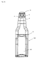
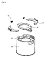
- the present invention relates to a fluid application device 90 as shown in FIG Fig. 6 and which is particularly suitable for use with pressure vessels such as aerosol cans 30, or fluid applicator devices suitable for pumping a disinfectant or conditioner in liquid, gel, emulsion or other form.
- pressure vessels such as aerosol cans 30, or fluid applicator devices suitable for pumping a disinfectant or conditioner in liquid, gel, emulsion or other form.
- the fluid application devices 90, 100 are all suitable for automatic fluid dispensing and have an application head 9 ', on which a sensor 4 and an outlet nozzle 5 for dispensing fluid are arranged.
- the nozzle 5 is in each case fluidically connected to a reservoir 30.
- the application head 9 ' has on its upper side an integrated dispensing arm, not shown separately, on which the nozzle, not shown figuratively, is arranged pointing downwards.
- the reservoir 30 is a pressurized aerosol can 30, as well as in Fig. 7a is shown, so that according to this realization of the fluid application device can be dispensed with means for conveying the fluid.
- the cover 16 of the application head 9 ' can be pushed up by flanges on the cover 16 and on the head, which virtually form a rail guide. The pushing up can also be done automatically and hydraulically. In this case, a small motor for carrying out the displacement should be provided in the application head 9 '.
- the valve is connected via a connecting piece to the nozzle for dispensing the fluid.
- a pressure vessel adapter piece is arranged, which serves to hold the pressure vessel 30 in the application device.
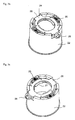
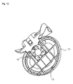
- a pressure vessel adapter piece is in a simple form in Fig. 7a to 7d It is designed as a clamping holder, wherein the clamping holder 24 has two by means of a respective clamping spring 25 biased Umgriffiata 25 ', which are arranged radially displaceably in the frame member 28 and thus pinch the head of the pressure box 8'.
- the clamping springs 25 can in the article 22 according to Fig. 7b and c be supported.
- the actuators, designed here as set screws 26, for biasing and loosening the clamping springs 25 are shown. By turning the screw thus the diameter of the clamping device can be tapered or widened, depending on the size of the pressure to be held, resulting in the adapter function.
- Fig. 7e shows the clamp holder 24 with the clamping springs 25 and the frame part 28 in exploded view, for arrangement in the article 22, which is cylindrical and at its top a recess with Abstützflansch 22 ', on which the clamping bracket 24 can be placed.
- the in Fig. 7b shows clamping bracket also directly into the adapter head 9 ' the fluid application device, as in Fig. 6 shown to be used.
- a jacket piece 9 which forms the quasi "housing" of the application device. It is closed in the direction of the operating side and has a cylindrical bulge, on the inside of the pressure cell, which can be inserted from below, is applied.
- a wall mount 10 is provided on the rear side of the application device 90, here without electronic feedthroughs.
- the application device 90 as well as the application device 100, with the screw clamp 19, as attached to the wall bracket 10 and in Fig. 1d is shown to be provided for attachment to a piece of furniture, such as a hospital bed or table, so that advantageously a practitioner, the sick person or visitors can disinfect the hands at any time and thus prevent germ transmission.
- FIG. 6 a collecting tray 11, which is directly cut to the shell portion and serves to collect excess fluid output. It can be used in a simple embodiment doppelbödig with inlaid absorbent, such as pads, which absorb the excess fluid and can be replaced accordingly, if the doppelbödige collection element 11, as proposed for unfolding is designed or at least the extraction and replacement of pads allows.
- absorbent such as pads
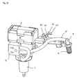
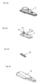
- the fluid application devices shown operate with reservoirs 30 ', from which the fluid can be obtained by the use of a pump 1, see Fig. 4 and Fig. 5h is encouraged.
- this is a diaphragm pump 1, which is coupled to a one-way valve 6 and has an inlet, which by means of a piece of tubing, the fluid from the storage vessel 30 ', see Fig. 1b , promotes.
- the pump is on the outlet side via its nozzle by means of a hose 5 "fluidly with the nozzle 5, or via the connecting piece 5 ', on which the nozzle 5 is arranged, see exploded view Fig. 4 , connected.
- FIG. 4 shows an arrangement variant for the battery magazine 2 in a vertical orientation, not intended for direct placement under the cover 16 of the application head.
- the fluid connection to the nozzle 5 via the nozzle 5 ' is also off Fig. 2c and Fig. 2f seen.
- the application head 9 'at the top of an application arm 15 designed as a limb, on the underside of the nozzle 5 is arranged to dispense the fluid.
- a sensor 4 may be provided on the vertical wall of the application head 9 ', alternatively, however, the sensor 4 could also be arranged immediately behind the nozzle 5 or also in front of the nozzle 5 when using a different design. It is also possible to use more than one sensor 4 if correspondingly additional tasks are provided except for triggering the pump with the sensor 4. Further tasks could be, for example, the determination of the body part size to be disinfected or to be supplied with fluid or its shape.
- the application head 9 ' has quasi-directly by a plurality of optical sensors, which allow reflection measurements, via devices for body part recognition.
- the storage vessel at least partially surrounds and advantageous, as in the embodiments of Fig. 1a . b and c shown extends to the lower bottom of the storage vessel 30 '.
- the embodiments shown allow the introduction of the storage vessel 30 'from the front bottom into the application device, so that the shell piece 9, the storage vessel 30' respectively engages. From below, the storage vessel 30 'extends as far as an adapter piece 8 which is in Fig. 4 , respectively Fig. 5 j, can be clearly seen.
- This Adapter piece 8 has an inwardly offset flange 8 ', which is brought into engagement with an opening 18 of the storage vessel.
- the adapter piece 8 forms a bottom to which the pump 1, see Fig. 5h And a battery cartridge housing 17 ( Fig. 5i ) for receiving a battery magazine 2, see Fig. 5f , can be held if it is not placed directly under the cover 16 ( Fig. 2e ).
- This floor has a passage opening 18, through which a delivery hose can be inserted.
- the battery magazine 2 can also be arranged at the top in the application head 9', wherein the batteries are arranged horizontally.
- This arrangement of the battery magazine 2 also shows Fig. 2d , Further the LEDs 21,21 'shows for indicating the operational readiness of the device and the actuating push buttons 31,31' for turning on and off of the device, also connected to the control and / or control circuit of the apparatus, a suitable way via the board 3, are operatively connected.
- Fig. 2e shows an insight into the application head 9 'with the LEDs 21,21', the battery magazine 2 and the electronic terminals of the batteries and the operation buttons 31,31 '.
- the perspective side view of the head of the fluid application device 9 'from Fig. 2f represents the connection of the nozzle 5 via the nozzle 5 ', which is connected to the tube 5 ", to the one-way valve 6 and the pump 1 and finally to the plug 7, which opens into the storage vessel, optionally via the adapter piece. 8 as it complements in Fig. 2g is shown. Further, in the illustrated embodiment, the operating push buttons 31, 31 'on the circuit board 3 and the LEDs 21, 21' showing whether the apparatus is ready or not are shown.
- the application head 9' can be provided with a cover 16. This can be in many different ways, either by engagement by means of flanges shown or by a hinge member, or placed in any other way and connected to the other housing of the application head 9 '. Thus, by simply opening the application head 9 'about the battery magazine 2 can be replaced by removal from the housing 17.
- Fig. 5b shows (see also Fig. 4 ) a board 3, on which a control and regulating unit is arranged, which is in operative connection with the sensor 4.
- the sensor 4 can, figuratively not shown, be arranged on the underside of the board 3.
- the sensor which may be an optical or opto-electronic sensor, and thus detected when changing the lighting conditions, such as triggered by the insertion of a hand under the sensor, so begins on the operative connection by means of the control and regulation Pump 1 operates and causes by appropriately opening the valve 6, the conveying of fluid from the storage vessel 30 'and outputting the fluid through the nozzle. 5
- the control device either allows pre-setting of fixed dispensing volumes, expressed in ml, to ensure that an operator decreases a sufficient amount of disinfectant or care fluid, or it can be a control device that operates in response to a hand size or fluid condition Connection with the hand size or skin texture, which can be measured by the opto-electronic sensor, is regulated. Therefore, it is also possible to provide a plurality of sensors 4 in order to visualize the outlines of a hand in a simple manner to determine. Thus, it is advantageously ensured with the invention that a reliable dispensing of disinfectant in relation to the required manual size-dependent supply is provided.
- the board 3 can with a cover 3 ', see Fig. 5a Are protected in the application head 9 '. In detail shows Fig.
- Fig. 5b the board with the operation buttons 31,31 'and the LEDs 21,21', which indicate the operating condition.
- the board cover 3 ' has corresponding receptacles and passages for these elements.
- Fig. 5c shows the viewing window 20 through which the LEDs 21,21 'can be seen from the outside.
- the cover 16 of the application head 9 ' has a recess for the viewing window 20, see Fig. 5d ,
- the application device 90,100 may be provided for example at a fixed preset output quantity a counter in the application head 9 'or as a separate handset that communicates with a signal generator in the application head.
- the counter counts the dispensed fluid cans and thus can follow the emptying of the storage vessel 30,30 'with.
- a receiving or reading device which makes the counted result, or the result determined, readable or readable, about a person who is responsible for refilling the storage containers, determine how many doses or which Quantity was spent.
- Such counters can communicate via radio frequency.
- the device according to the invention can be programmed when a chip on the board permits this, for instance to set output cans to fluid or to define a warning tone when emptying. Such programming can be done via a handset, which is also part of the counter device.
- the various application devices 90, 100 may be provided with corresponding codes, so that it is clearly clear to a person who is responsible for refilling which of the application devices 90, 100 needs replenishment.
- FIG. 2a and 2 B show Fig. 2a and 2 B the application head 9 '
- Fig. 2b shows a recessed from the edge flange 8 'of the adapter piece 8, which is arranged on the application head, for use in the opening of a storage vessel 30'.
- Fig. 2b a viewing window 20 present on the cover 16 of the application head 9 ', which makes it possible to look into the application head 9' and to determine whether the green LED 21 (see FIG. 21 ) is lit, indicating that the device is ready for operation; or if the red LED 21 'is lit, indicating that the device is not ready.
- the LEDs 21,21 ' can be connected to the control and control circuit. Of course, other colors are selectable for the LEDs 21, 21 ', or a flashing or other display mode can be established.
- the counter If the counter outputs optically readable signals, it can be read out via the viewing window 20 by means of the corresponding read-out device.
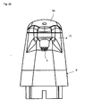
- FIG. 3a an application device 100 according to the invention is also shown with the viewing window 20, in which extends to receive large storage vessels of the shell piece 9 downwards, whereas the top view of such a device in Fig. 3b from above an embodiment with a slightly narrower shell element 9 shows.
- the further jacket piece is also in Fig. 1c compared to Fig. 1b clarified, in which the scope of the shell element 9 and 9 'application head is approximately equal.
- Fig. 8a in plan view, a collecting tray 11, which adjoins directly to the lower edge of the shell piece, and which serves to receive excess fluid output.
- the drip tray 11 is designed as doppelbödiges element, at its upper side of the upper bottom 1 "it has through openings 11 ', through which the fluid can flow down.
- absorbents such as pads, but also particulate material or absorbent fleece.
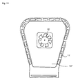
- a suction rotor 12 which can be set in motion directly by appropriate electronic coupling of the drive with the sensor 4, when the sensor triggers the fluid output. Once the suction device is set in motion, the excess fluid is safely taken up by the drip tray 11 and pulled there even with appropriate design there to a collection reservoir. This can just be provided with the appropriate absorbent. While Fig. 8a and 8b show an approximately oval drip tray 11, is another design of the drip tray 11 in Fig. 11 shown, there is also a Absaugrotor 12 is provided. An upper floor 11 'of the collecting bowl 11, which is designed in a double-bottomed manner, has at the edge the passage openings 11 "in order to drain off fluid, but it can also be designed as a sieve or a network component.
- Fig. 9a shows the transition of the collecting tray 11 in the jacket element 9 'in elegant curved embodiment, which also in Fig. 9b can be seen from the side, the drip tray 11 goes harmoniously directly into the jacket piece 9 'on.
- a one-piece design of the collecting tray 11 is possible when a holding element holds a provided under the collecting tray 11 fluid absorbent; in Fig. 9b However, a permeable topsoil 11 'is shown.
- FIG. 10 an embodiment of the drip tray 11 is again illustrated:
- the tops of the drip tray 11 are seen in a standing and lying position in the middle or right, while reference numeral 13 as a holding means for a pad under the top 11 'clampable shell 13' shows.
- Reference numeral 12 denotes the rotor and the reference numerals 14, 14 'electronic connection elements, or the contactor and the E-contact plug 14'.
- Fig. 12 shows a view of such equipped with suction rotor 12 drip tray from below.
- Fig. 13a and 13b show two views of a suitable wall suspension element or a plate which is particularly suitable for supporting a fluid application device 90, 100 on a wall.
- the wall mount 10 may, if necessary, have through openings for electronic lines.
- a clamp 10 ' is used to hold a drip tray 111, which is not attached to a shell piece 9, under the application head 9' or the device with jacket piece 9.
- the wall mount 10 can also serve for attaching the fluid application device 90, 100 to a bed, table, shelf or the like and thus be mounted in a suitable reach for a notified user.
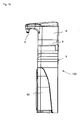
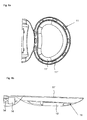
- Fig. 14 and Fig. 1d show finally that the jacket piece 9 may well be so designed that the storage vessel 30 'may be covered.
- the shell piece 9 has a front articulated hinged portion 32.
- the hinge is here a hinge which is attached to the lower edge of the shell piece 9 and which allows the application device 100 to open for easy storage vessel exchange.
- the closed variant shows Fig. 1d while Fig. 14 the unfolded variant shows.
- the front portion of the shell piece 9 can also be pushed or plugged on a rail guide.
- the jacket piece 9 may further be formed so that it has on its inside for flexible use of the device has a lift, the indicating smaller Storage vessels 30 'to the adapter 8 allowed.
- a lift device comprises a contact surface 34 for the storage container 30 'and a rail element 34', so that the contact surface forms a vertically displaceable bottom on the jacket piece 9. This small bottles can be easily placed on the footprint 34 and drove to the adapter piece 8.
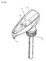
- FIGS. 15b to d An embodiment of the fluid application device with an adapter piece 8 as a union nut is in FIGS. 15b to d shown.
- the union nut is fitted over a Aufsteck Published with a circumferential groove on a lower neck on the application head 9 'and connected to this.
- the funding is there a coaxial feed pipe 33 whose inner tube forms the battery magazine 2, which is connected to the power supply to the pump 1 and the sensor 4.
- the pump 1 is lying in the head 9 'arranged, which has a shapely narrow application arm 15.
- a storage bottle of disinfectant or other fluid equipped with this application device can be placed in a support to improve stability.
Abstract
Description
Die Erfindung betrifft eine berührungslos arbeitende Fluid-Applikationsvorrichtung, die insbesondere zur Verbesserung der Hygiene geeignet ist.The invention relates to a non-contact fluid application device, which is particularly suitable for improving hygiene.
Gerade auch im medizinischen Bereich ist Hygiene ein besonders relevantes Thema: Noch immer infizieren sich pro Jahr in Deutschland 400.000 bis 600.000 Menschen während eines Aufenthaltes in einem Krankenhaus mit pathogenen Erregern, bis zu 30.000 Menschen sterben an den Folgen dieser teilweise sehr schweren Infektionen. Es wird davon ausgegangen, dass bis zu 90 % dieser nosokomialen Infektionen über die Hände übertragen werden. Aus diesem Grunde gehört die hygienische Handdesinfektion zu den wichtigsten Maßnahmen der Prophylaxe nosokomialer Infektionen im Besonderen und bzw. Infektionskrankheiten allgemein. Die Zielsetzung der Handdesinfektion ist in erster Linie die Verhinderung der Weiterverbreitung von auf die Hand gelangten Krankheitserregern.Hygiene is a particularly relevant topic, especially in the medical field: between 400,000 and 600,000 people are still infected each year in Germany with pathogens during a stay in a hospital. Up to 30,000 people die as a result of these very severe infections. It is believed that up to 90% of these nosocomial infections are transmitted by the hands. For this reason, hygienic hand disinfection is one of the most important measures for the prophylaxis of nosocomial infections in particular and / or infectious diseases in general. The goal of hand disinfection is primarily to prevent the spread of hand-held pathogens.
Die Übertragung von Infektionskrankheiten (Bakterien oder Viren) erfolgt vorwiegend über Tröpfcheninfektion oder Schmierinfektion. Bei beiden Übertragungswegen spielen die Hände jedoch eine entscheidende Rolle. Handdesinfektion betrifft also nicht nur den medizinischen Sektor wie Krankenhäuser, Praxen und sonstige medizinische Einrichtungen, sondern auch alle Bereiche, in denen Menschen direkt oder indirekt miteinander in Berührung kommen.The transmission of infectious diseases (bacteria or viruses) takes place predominantly via droplet infection or smear infection. However, hands play a crucial role in both transmission paths. Hand disinfection therefore not only affects the medical sector, such as hospitals, practices and other medical facilities, but also all areas where people come into direct or indirect contact with each other.
Aufgrund der in letzter Zeit aufgetretenen Infektionskrankheiten wie etwa der Schweinegrippe und der Vogelgrippe und deren Präsenz in den Medien, ist ein Wandel in der Wahrnehmung der Menschen bezüglich hygienischer Maßnahmen zu beobachten: Die Handdesinfektion hat den Sprung aus dem Bereich des Krankenhauses in den Endkonsumerbereich geschafft und wird als geeignete Vorsorgemaßnahme von einem Großteil der Bevölkerung wahrgenommen.Due to recent infectious diseases such as swine flu and avian influenza and their presence in the media, a change in the perception of people in terms of hygiene measures is observed: Hand disinfection has made the leap from the hospital to the final consumption area and is perceived as a suitable precautionary measure by a large part of the population.
Handdesinfektionsmittel werden im Allgemeinen in Spenderflaschen im freien Handel und Fachhandel angeboten. Die Applikation des Handdesinfektionsmittels auf die Hand erfolgt über mechanische Dosierer oder einfach durch Aufträufeln des Mittels auf die Hand. Dabei werden ca. 3 ml des Mittels auf die Handinnenfläche gegeben und sollen dann über eine vom Hersteller vorgegebene Zeit (Einwirkzeit) zwischen den Händen und Fingern verrieben werden. Problematisch hierbei ist die teilweise unzureichende Benetzung der Haut z. B, zwischen den Fingern und unter den Fingernägeln durch den Anwender.Hand sanitizers are generally offered in dispenser bottles in the free trade and specialized trade. The application of the hand disinfectant on the hand via mechanical dosing or simply by dropping the agent on the hand. About 3 ml of the product are applied to the palms of the hands and are then to be rubbed between the hands and fingers for a time specified by the manufacturer (exposure time). The problem here is the partially insufficient wetting of the skin z. B, between the fingers and under the fingernails by the user.
Dieses Problem wird durch automatisierte Spendersysteme minimiert, bei denen die Applikation durch automatisches Aufsprühen des Präparates erfolgt. Der Anwender hält beide Handinnenflächen so in Bezug zu einem Sensor einer automatisierten Spendervorrichtung, wonach der Sensor den Aussprühvorgang einer genau definierten Menge an Handdesinfektionsmittel auf beide Handinnenflächen des Anwenders initiiert.This problem is minimized by automated dispensing systems in which the application is carried out by automatic spraying of the preparation. The user holds both palms in relation to a sensor of an automated dispenser device, after which the sensor initiates the spraying of a well-defined amount of hand sanitizer onto both palms of the user.
Außer Desinfektionsmitteln sind jedoch auch Dosiervorrichtungen für andere Fluide wie Pflegemittel und Cremelotionen aus dem Stand der Technik hinreichend bekannt. Einfache Dosiervorrichtungen arbeiten dabei mit handbetätigbaren Pumpen und geben eine Dosis des Fluids nach einem Pumphub ab.In addition to disinfectants, however, metering devices for other fluids such as care products and cream lotions from the prior art are well known. Simple dosing devices work with manually operable pumps and deliver a dose of the fluid after a pumping stroke.
Einen Dosierspender, der es erlaubt, eine vorbestimmte Menge eines Fluids zu entnehmen, offenbart die
Weiter sind aus dem Stand der Technik verschiedene Dosiervorrichtungen bekannt, die von einem Gehäuse umgeben an einer Wand befestigt sein können oder in eine Fläche integriert sein können, die eine Waschvorrichtung umgibt. Gemeinsam sind diesen Dosierspendern Pumpvorrichtungen, die manuell aktiviert werden, meist mittels eines Hebels oder Druckknopfs, um eine mehr oder minder flüssige Substanz auszugeben. Die Pumpvorrichtung wird häufig als Kolbenpumpe realisiert. Einen weiteren Spender für Seife, Handlotion, Desinfektionsmittel oder dergleichen beschreibt die
Es gibt ferner Dosiervorrichtungen, die die berührungslose Ausgabe des Dosiergutes erlauben. Solche Vorrichtungen sind in der
Ferner gibt es bereits Vorrichtungen zur Desinfektion, die es zusätzlich ermöglichen, sowohl Desinfektions-, als auch Handreinigungsmittel sensorgesteuert auszubringen und zugleich Überschussflüssigkeit aufzufangen. Dazu beschreibt etwa die
Nachteile dieser Vorrichtungen können darin gesehen werden, dass diese alle inflexibel einsetzbar und hinsichtlich ihrer Ausgestaltung entweder an eine bestimmte Vorratsgehälterform gebunden sind, damit ein Sensor basierter Spenderkopf sicher aufmontiert werden kann; oder dass sie sehr einfach gestaltet sind, so dass ein schlichter Förderschlauch in ein beliebiges Vorratsgefäß geführt werden kann, wobei diese Ausführungsformen weniger sicher in der Handhabung und Anordnung sind und gegebenenfalls eine Gesamtanordnung bilden, die wenig ansprechend ist und insofern einen Anwender auch nicht zur Benutzung animiert.Disadvantages of these devices can be seen in the fact that they are all used inflexible and in terms of their design are either bound to a particular Vorratsgehälterform so that a sensor-based dispenser head can be mounted safely; or that they are very simple, so that a simple delivery hose can be fed into any storage vessel, these embodiments are less secure in handling and arrangement and optionally form an overall arrangement, the less appealing and thus does not encourage a user to use.
Ausgehend von diesem Stand der Technik ist es wünschenswert, eine Dosiervorrichtung zur Applikation von Fluiden, insbesondere zur Desinfektion, zu schaffen, die einerseits automatisiert betreibbar und andererseits flexibel verwendbar für verschiedene Vorrichtungsgefäße ist und die dabei dennoch eine zur Benutzung animierende Form aufweist.Based on this prior art, it is desirable to provide a metering device for the application of fluids, in particular for disinfection, on the one hand automated operable and on the other hand flexibly usable for different device vessels and still has an animating for use form.
Diese Aufgabe wird durch die Fluid-Applikationsvorrichtung mit den Merkmalen der unabhängigen Ansprüche 1 und 2 gelöst.This object is achieved by the fluid application device having the features of
Bevorzugte Weiterbildungen werden durch die Unteransprüche beschrieben.Preferred developments are described by the subclaims.
In einer ersten Ausführungsform bezieht sich die erfindungsgemäße Fluidapplikationsvorrichtung mit automatischer Fluidausgabe auf eine Vorrichtung, die wenigstens einen Applikationskopf umfasst, der mit einem oder mehreren Sensoren und einer Düse ausgestattet ist, durch die Fluid ausgegeben werden kann. Die Düse ist dabei mit einem Vorratsbehälter fluidisch verbunden. Der Applikationskopf weist an seiner Oberseite einen Ausgabearm auf, an dem nach unten weisend die Düse angeordnet ist. Der Vorratsbehälter ist in dieser Ausführung der Erfindung ein unter Überdruck stehendes Gefäß, wie eine Druckdose, das, beziehungsweise die, einen Auslass aufweist, der durch ein Ventil geöffnet und geschlossen werden kann. In dem Applikationskopf liegt eine Steuerungseinheit vor, um sensorgesteuert das Öffnen und Schließen des Ventils zu veranlassen. Das Ventil ist über ein Verbindungsstück mit der Düse verbunden, so dass über die Düse das Fluid ausgegeben werden kann, wenn durch den Sensor veranlasst das Öffnen des Ventils mit einem entsprechenden Öffnungsmittel veranlasst wird. Weiter ist an dem Applikationskopf ein erfindungsgemäßes Druckgefäßadapterstück vorgesehen, das dazu dient, das Druckgefäß an dem Applikationskopf zu halten und das verschiedene Druckgefäßdosen halten kann.In a first embodiment, the fluid delivery automatic fluid delivery device of the invention relates to a device comprising at least one application head equipped with one or more sensors and a nozzle through which fluid can be dispensed. The nozzle is fluidly connected to a reservoir. The application head has on its upper side an output arm, on which the nozzle is arranged pointing downwards. The reservoir is in this embodiment of the invention, a pressurized vessel, such as a pressure box, which, or the, an outlet, which can be opened and closed by a valve. A control unit is present in the application head in order to trigger the opening and closing of the valve in a sensor-controlled manner. The valve is connected to the nozzle via a connecting piece, so that the fluid can be dispensed through the nozzle when the sensor causes the opening of the valve with a corresponding opening means. Further, an inventive pressure vessel adapter piece is provided on the application head, which serves to hold the pressure vessel to the application head and can hold the various pressure vessel cans.
Durch diese Ausführungsform der Erfindung ist es möglich, ohne Zufuhr von externer Energie zum Pumpen des Fluids aus dem Vorratsbehälter zur Düse die Fluidausgabe zu tätigen. Es ist hierbei lediglich eine äußerst geringe Energiemenge erforderlich, um den Sensor zu betreiben. Damit kann dieses Gerät grundsätzlich batteriebetrieben werden, es ist daher von einer Netzversorgung unabhängig einsetzbar.By this embodiment of the invention it is possible without supply of external Energy to pump the fluid from the reservoir to the nozzle to make the fluid output. It is only a very small amount of energy required to operate the sensor. Thus, this device can basically be battery operated, it is therefore used independently of a mains supply.
In einer weiteren Ausführungsform kann die Fluid-Applikationsvorrichtung mit automatischer Fluidausgabe, die ebenfalls einen Applikationskopf umfasst, der einen Sensor und eine Düse zum Ausgeben von Fluid aufweist, so gestaltet sein, dass der Sensor mit einer mit der Düse verbundenen Pumpe, die an den Vorratsbehälter angeschlossen ist, operativ verbunden ist. Weiter hat dieser Applikationskopf an seiner Oberseite einen Ausgabearm, an dem nach unten weisend die Düse angeordnet ist, wobei in dieser Ausführungsform in dem Applikationskopf eine motorbetriebene und durch den Sensor steuerbare Pumpe mit einem Ein- und einem Ausgang für Fluid angeordnet ist. Die Pumpe ist über ein Ventil ausgangsseitig mittels einer Schlauch- oder Rohrverbindung und mit einem Verbindungsstutzen der Düse, respektive einem Anschlussstück, zur Ausgabe des Fluids verbunden. Weiter ist die Pumpe über einem Adapterstück angeordnet und kann mit diesem mit einem Vorratsgefäß fluiddicht verbunden werden.In another embodiment, the automatic fluid dispensing fluid application device, which also includes an application head having a sensor and a nozzle for dispensing fluid, may be configured such that the sensor is connected to a pump connected to the nozzle and to the reservoir connected, is operatively connected. Furthermore, this application head has on its upper side an output arm, on which the nozzle is arranged pointing downwards, wherein in this embodiment a motor-driven pump controllable by the sensor is arranged with an inlet and an outlet for fluid in the application head. The pump is connected via a valve on the output side by means of a hose or pipe connection and with a connection nozzle of the nozzle, or a connecting piece, for dispensing the fluid. Further, the pump is disposed over an adapter piece and can be connected to this fluid-tight with a storage vessel.
Dabei kann das Adapterstück an dem Applikationskopf dauerhaft oder lösbar angeordnet sein. Dies erfolgt über die Unter- oder Innenseite des Adapterstücks, die mit einer Vorratsgefäß-Öffnung in Eingriff gebracht werden kann, so dass sich eine Fördervorrichtung, insbesondere ein Schlauch oder ein Rohr von der Eingangsseite der Pumpe in das Vorratsgefäß erstreckt.In this case, the adapter piece can be permanently or detachably arranged on the application head. This is done via the bottom or inside of the adapter piece, which can be brought into engagement with a storage vessel opening, so that a delivery device, in particular a hose or a pipe from the input side of the pump extends into the storage vessel.
Das Adapterstück kann so gestaltet sein, dass seine Oberseite formschlüssig mit dem Applikationskopf verbindbar ist und seine Unterseite einen Flansch aufweist, insbesondere einen Flansch, der von einem Rand des Adapterstücks nach innen versetzt ist und der mit der Öffnung des Vorratsgefäßes in Eingriff gebracht werden kann, indem der Flansch einen Vorratsgefäß-Hals umgreift oder in diesen eintaucht. Ein Förderschlauch erstreckt sich von der Eingangsseite der Pumpe durch eine in dem Adapterstück vorgesehene Öffnung in das Vorratsgefäß, um so das Fluid auf aktiv Werden des Sensors hin zu fördern.The adapter piece can be designed so that its upper side can be positively connected to the application head and its underside has a flange, in particular a flange which is offset inwardly from an edge of the adapter piece and which can be brought into engagement with the opening of the storage vessel, by the flange engages around a reservoir neck or immersed in this. A delivery hose extends from the input side of the pump by an opening provided in the adapter piece into the storage vessel, so as to promote the fluid to actively become the sensor out.
Die Aktivierung des Sensors in den erfindungsgemäßen Ausführungsformen erfolgt durch das Hinführen eines Körperteils, wie insbesondere einer Hand, oder alternativ eines Fußes, in den Erfassungsbereich des SensorsThe activation of the sensor in the embodiments according to the invention takes place by the introduction of a body part, in particular a hand, or alternatively a foot, into the detection area of the sensor
Die Sensoren, die für die erfindungsgemäße Fluid-Applikationsvorrichtung gemäß beider Ausführungsformen besonders geeignet sind, sind optische oder optoelektronische Sensoren. Die Applikationsvorrichtung kann dabei mit mehreren Sensoren ausgestattet sein, wobei jedoch zumindest ein Sensor an dem Ausgabearm entweder nach unten weisend oder an dem Applikationskopf in Richtung der Düse weisend angeordnet ist, um so eine aktivierende Hand, die unter die Düse geführt wird, in jedem Fall zu detektieren. Um vorteilhaft eine Handform oder eine Fußform zu bestimmen, kann der Sensor Reflexion messen. Bei der Reflexionsmessung ist es sogar möglich, Falten in der Körperhaut wahrzunehmen und aus der Tiefe von Falten auf den Bedarf an Desinfektionsmittel oder an Pflegefluid rückzuschließen, das durch die Applikationsvorrichtung ausgegeben wird.The sensors which are particularly suitable for the fluid application device according to the invention according to both embodiments are optical or optoelectronic sensors. The application device can be equipped with a plurality of sensors, but at least one sensor is arranged on the output arm facing either down or on the application head in the direction of the nozzle, so as an activating hand, which is guided under the nozzle, in each case to detect. To advantageously determine a hand shape or a foot shape, the sensor can measure reflection. In the reflection measurement, it is even possible to perceive wrinkles in the body skin and to deduce from the depth of wrinkles on the need for disinfectant or nursing fluid, which is output by the application device.
Es ist auch möglich, mehrere Sensoren an dem Ausgabearm und/oder der vertikalen Wandung des Applikationskopfes vorzusehen, um eine genauere Bestimmung der Größe und Körperteilform des mit Fluid zu versehenden Körperteils zu ermitteln.It is also possible to provide a plurality of sensors on the delivery arm and / or the vertical wall of the application head to determine a more accurate determination of the size and body part shape of the body part to be fluidized.
In der Variation der Ausführungsform, bei der das Fluid gepumpt werden muss, bei der also der Sensor operativ mit einer Pumpe gekoppelt ist, so dass das Auslösen durch den Sensor den Pumpenantrieb tätig werden lässt, wird eine Membranpumpe bevorzugt, die ausgangsseitig mit einem Einwegventil operativ gekoppelt ist. Die Membranpumpe muss durch eine Energieversorgungseinheit versorgt werden, wobei es sich zwar um eine Netzversorgung mittels einer dem Fachmann bekannten Netzleitung und entsprechenden Bauteilen handeln kann, wobei jedoch bevorzugt ein in seiner Gesamtheit austauschbares Batteriemagazin vorzusehen ist, das entsprechend in elektrischem Kontakt mit der Pumpe steht. Durch die Gestaltung als Magazin oder Kartusche kann das lästige Austauschen einzelner Batterien entfallen und das gesamte Magazin kann vorteilhaft mit einem Griff aus der Fluid-Applikationsvorrichtung entnommen werden. Besonders vorteilhaft kann dazu der Applikationskopf geöffnet werden, beispielsweise durch das Vorsehen einer öffenbaren Kopfabdeckung.In the variation of the embodiment in which the fluid must be pumped, that is, the sensor is operatively coupled to a pump so that the triggering by the sensor causes the pump drive to operate, a diaphragm pump operating on the output side with a one-way valve is preferred is coupled. The membrane pump has to be supplied by a power supply unit, which may be a mains supply by means of a power line known to the person skilled in the art and corresponding components, but preferably a battery magazine which can be exchanged in its entirety is to be provided, which is correspondingly in electrical contact with the pump. The design as a magazine or cartridge eliminates the annoying replacement of individual batteries and the entire magazine can be advantageously removed with a handle from the fluid application device. For this purpose, the application head can be opened to particular advantage, for example by the provision of an openable head cover.
Der eine oder die mehreren Sensoren ist/sind über eine Steuerungs- und/oder Steuerungs- und Regelungseinheit mit der Pumpe operativ gekoppelt, die auf einer Platine angeordnet sein kann. So ist es möglich, die Ausgabevolumina des Fluids zum Einen voreinzustellen oder zum Anderen abhängig von Form, Größe, Hautfaltentiefe oder anderen Regelungsparametern zu regeln.The one or more sensors is / are operatively coupled via a control and / or control unit to the pump, which may be disposed on a circuit board. Thus, it is possible to preset the output volumes of the fluid on the one hand or to regulate the other depending on the shape, size, skin fold depth or other control parameters.
Bei der Ausführungsform, bei der das Vorratsgefäß eine Druckdose ist, dient die Steuerungseinheit dem Steuern des Ventils, sie kann jedoch zusätzlich als Steuerungs- und Regelungseinheit ausgebildet sein, um ebenfalls in Abhängigkeit der Handgröße, Form und den weiteren genannten Parametern eine Ausgabemenge eines Fluids zu regeln. In Frage kommen hierbei abgestufte ml-Einteilungen von 0,5 in Halbmilliliterstufen aufsteigend bis etwa 3,0 ml, es ist jedoch auch möglich, hier die Ventilöffnungszeit stufenlos einzustellen. Ebenso kann, allerdings bei der Variante, bei der ein Pumpenhub getätigt wird, auch eine nahezu stufenlose Einstellung erfolgen.In the embodiment in which the storage vessel is a pressure cell, the control unit is used to control the valve, but it can also be designed as a control and regulation unit, also to an output quantity of a fluid depending on the hand size, shape and the other parameters mentioned regulate. In this case, graduated ml graduations of 0.5 in half milliliter stages ascending to about 3.0 ml, but it is also possible here to adjust the valve opening time infinitely. Likewise, however, in the variant in which a pump stroke is made, also take place a nearly stepless adjustment.
Bei der Variante, bei der ein Förderschlauch die Pumpe mit dem Vorratsgefäß verbindet und wobei der Förderschlauch durch die Öffnung des Adapterstücks geführt wird, kann wie ein durchbohrter Stopfen, insbesondere ein Stopfen mit Doppellochführung in dem Adapterstück vorgesehen sein, durch den der Förderschlauch abdichtend in der Öffnung befestigt wird.In the variant in which a delivery hose connects the pump to the storage vessel and wherein the delivery hose is passed through the opening of the adapter piece, can be provided as a perforated plug, in particular a plug with double hole guide in the adapter piece, through which the delivery hose sealing in the Opening is attached.
Vorteilhaft weist die Fluid-Applikationsvorrichtung, insbesondere in dem Applikationskopf angeordnet, eine Vorrichtung zur Dichtemessung des Fluids, und/oder eine Vorrichtung zur Hand- und Hautbeschaffenheitserkennung, wie bereits durch die Sensoren erläutert, oder alternativ oder zusätzlich eine Vorrichtung zur Handgrößenbestimmung auf, was ebenfalls durch die genannten Sensoren realisiert werden kann. Die Vorrichtungen zur Handgrößen- oder Hautbeschaffenheitsbestimmung sind operativ mit der Steuerungs- und/oder Regelungsvorrichtung für die Pumpe beziehungsweise für das Ventil gekoppelt.Advantageously, the fluid application device, in particular arranged in the application head, a device for measuring the density of the fluid, and / or a device for hand and skin texture recognition, as already by the sensors explained, or alternatively or additionally, a device for determining the size of the hand, which can also be realized by said sensors. The hand size or skin condition determination devices are operatively coupled to the control and / or regulating device for the pump or valve, respectively.
Die erfindungsgemäße Fluid-Applikationsvorrichtung kann ferner auch so gestaltet sein, dass das Adapterstück als eine Überwurfmutter ausgebildet und mit dem Applikationskopf verbunden ist. Diese Gestaltung ist besonders deshalb praktisch, weil die Überwurfmutter quasi auf jede Flaschengröße mit Hals-Außengewinde geschraubt werden kann; ggfs. kann das Adapterstück mit Überwurfmutter entsprechend ausgewählt und am Applikationskopf ausgetauscht werden. Platzsparend und ästhetisch ist die Fördervorrichtung dort ein doppelwandiges Förderrohr, insbesondere ein Koaxial-Förderrohr, dessen Innenrohr das Batteriemagazin bildet, das zur Energieversorgung zumindest mit der Pumpe, insbesondere mit der Pumpe und einem oder weiteren in dem Applikationskopf vorliegenden Energieverbrauchern elektrisch verbunden ist. Zusätzlich kann eine Vorratsflasche mit Desinfektionsmittel oder einem anderen Fluid, die mit dieser Applikationsvorrichtung ausgestattet ist, in eine Halterung zur Verbesserung der Standsicherheit eingesetzt werden.The fluid application device according to the invention can also be designed so that the adapter piece is formed as a union nut and connected to the application head. This design is particularly useful because the nut can be screwed on virtually any bottle size with neck external thread; if necessary, the adapter piece with union nut can be selected accordingly and replaced on the application head. Space saving and aesthetically, the conveyor there is a double-walled conveyor pipe, in particular a coaxial feed pipe whose inner tube forms the battery magazine, which is electrically connected to the energy supply at least with the pump, in particular with the pump and one or more present in the application head energy consumers. In addition, a storage bottle of disinfectant or other fluid equipped with this application device can be placed in a holder to improve stability.
Sowohl das Druckgefäßadapterstück für Druckdosen, als auch das Adapterstück für nicht unter Druck stehende Flaschen oder Gefäße kann sich in ein Mantelstück, respektive ein Gehäuse, erstrecken, das zumindest einen Abschnitt des Vorratsgefäßes umgibt. So wird die Vorrichtung optisch attraktiv und kann zur Anbringung oder Stabilisierung weitere Funktionen erfüllen oder Elemente zur Erfüllung von Aufgaben wie Stabilisierung oder Wandanbringung oder weiteres aufnehmen.Both the pressure vessel adapter piece for pressure cans, as well as the adapter piece for non-pressurized bottles or vessels may extend into a shell piece, or a housing, which surrounds at least a portion of the storage vessel. Thus, the device is visually attractive and can perform additional functions for attachment or stabilization or include elements to fulfill tasks such as stabilization or wall mounting or more.
Das Mantelstück kann dabei bei einer zur Wandanordnung vorgesehenen Fluid-Applikationsvorrichtung so ausgebildet sein, dass es an seiner zur Wand weisenden Seite oder an der Bodenseite geöffnet ist, um so das Einführen des Vorratsbehälters zu erlauben. Die Wandbefestigung kann über eine Wandhalterung erfolgen. Im Übrigen kann das Mantelstück auch einstückig mit der Wandhalterung ausgebildet sein.In this case, the jacket piece may be formed in a fluid application device provided for the wall arrangement in such a way that it is open on its side facing the wall or on the bottom side so as to introduce the storage container to allow. The wall mounting can be done via a wall bracket. Incidentally, the shell piece can also be formed integrally with the wall bracket.
Weiter kann zur flexiblen Nutzung der Vorrichtung das Mantelstück oder die mit diesem einstückig ausgebildeten Wandhalterung innenseitig eine Liftvorrichtung aufweisen, die aus einer Aufstandsfläche für das Vorratsgefäß und einem Schienenelement besteht, so dass die Aufstandsfläche einen vertikal verschiebbaren Boden an dem Mantelstück bildet. Damit können kleine Flaschen einfach auf die Aufstandsfläche gestellt und zu dem Adapterstück hingefahren werden.Further, for flexible use of the device, the shell piece or the integrally formed with this wall mount inside a lift device comprising a footprint for the storage vessel and a rail element, so that the footprint forms a vertically displaceable bottom of the shell piece. This small bottles can be easily placed on the footprint and drove to the adapter piece.
Alternativ zur Wandbefestigung kann an der Wandhalterung eine Schraubklemme angebracht sein, so dass die Applikationsvorrichtung vorteilhaft an einem horizontalen Tragarm oder einem Möbel mit horizontal ausgerichteter Befestigungsfläche angeordnet sein kann.As an alternative to wall mounting, a screw clamp can be attached to the wall mount so that the application device can advantageously be arranged on a horizontal support arm or a piece of furniture with a horizontally oriented attachment surface.
Ferner kann, gerade bei einer Ausbildung der Fluid-Applikationsvorrichtung als Stand-Element, das Mantelstück sensorseitig beziehungsweise betätigungsseitig offen sein, so dass das Vorratsgefäß von vorne eingeführt beziehungsweise eingesteckt werden kann. Auch hier, bei der Variation als Stand-Bauteil, kann das Einführen eines Vorratsgefäßes von unten erfolgen, so dass auch die Möglichkeit besteht, das Mantelstück so zu gestalten, dass es das Vorratsgefäß umfänglich vollständig umgibt.Furthermore, especially when the fluid application device is designed as a stationary element, the jacket piece can be open on the sensor side or on the actuating side, so that the storage container can be inserted or inserted from the front. Again, in the variation as a stand component, the insertion of a storage vessel can be done from below, so that there is also the possibility of making the shell piece so that it completely surrounds the storage vessel circumferentially.
Dabei kann ein vorderer Abschnitt des Mantelstück der den zur Hand weisenden Umfangsabschnitt des Vorratsgefäßes verhüllt, gelenkig aufklappbar und über ein Scharnier, das an diesem Teil und dem unteren Rand des Mantelstücks vorliegt, angeleckt sein. Es kann statt der gelenkigen Anordnung auch durch eine Ausführung mit einem Schienenpaar mit jeweils korrespondierenden Elementen an den beiden Mantelstück- und vorderen Abschnittsrändern von unten aufgeschoben werden.In this case, a front portion of the shell piece of the facing to the hand peripheral portion of the storage vessel, hinged hinged and a hinge which is present at this part and the lower edge of the shell piece, be licked. It can be pushed from below instead of the articulated arrangement by a design with a pair of rails with each corresponding elements on the two Mantelstück- and front section edges.
Das Mantelstück erstreckt sich bei einer Ausgestaltung als besonders formschöne Applikationsvorrichtung vorzugsweise bis an den unteren Rand des Vorratsgefäßes oder darüber hinaus. An dem unteren Rand des Mantelstückes kann eine Auffangtropfschale vorgesehen sein, die sich entsprechend der Ausdehnung des Ausgabearms unter diesen erstreckt, um überschüssiges Fluid aufzunehmen. Dies kann erforderlich sein, wenn der Bediener der Applikationsvorrichtung beispielsweise zwei Ausgabevorgänge auslöst und dabei feststellt, dass zuviel Fluid ausgegeben wird und die Hand weg zieht. Gerade im Fall von Desinfektionsmitteln, die alkoholisch oder aggressiv sein können und insofern zu lästigen und unerwünschten Dämpfen führen können, kann die Auffangtropfschale gute Dienste leisten.In one embodiment, the jacket piece extends as a particularly shapely application device, preferably as far as the lower edge of the storage vessel or beyond. At the lower edge of the shell piece, a drip tray may be provided which extends thereunder according to the extent of the dispensing arm to receive excess fluid. This may be necessary if the operator of the application device triggers two dispensing operations, for example, and notes that too much fluid is being dispensed and the hand is pulling away. Especially in the case of disinfectants, which can be alcoholic or aggressive and thus can lead to annoying and unwanted vapors, the drip tray can perform well.
In einer Ausführungsform kann die Auffangschale einen doppelten Boden aufweisen. Dabei hat der obere Boden mehrere Durchtrittsöffnungen, um das Fluid abfließen zu lassen, wobei die Durchtrittsöffnungen vorzugsweise am Rand der Auffangschale vorgesehen sein können. Am unteren Boden kann eine Absaugvorrichtung, wie beispielsweise ein zum Absaugen betriebener Rotor, der so in fluidischem Kontakt mit den Durchtrittsöffnungen steht, das überschüssige Flüssigkeit unmittelbar durch die Durchtrittsöffnungen nach unten weg gesaugt wird.In one embodiment, the drip tray may have a double bottom. In this case, the upper floor has a plurality of passage openings to allow the fluid to flow, wherein the passage openings can be preferably provided at the edge of the drip tray. At the lower bottom, a suction device, such as a driven for suction rotor, which is in fluidic contact with the passage openings, the excess liquid is sucked directly through the passage openings downwards.
Vorteilhaft ist daher am oder im unteren Boden des doppel- oder mehrbödigen Elements eines oder mehrere Absorptionsmittel für Fluid angeordnet. Statt eines doppelten Bodens kann hier auch einfach eine Haltestruktur für ein Absorptionsmittel wie ein Pad angebracht sein. Hierbei kann es sich entweder um bekannte partikuläre Absorptionsmittel handeln, jedoch auch um ein Saugvlies oder ein Saugpad, abhängig davon, wie die chemische Beschaffenheit des auszugebenden Fluids ist.Advantageously, therefore, one or more absorption media for fluid is arranged on or in the lower bottom of the double or multiwall element. Instead of a double bottom, a holding structure for an absorbent such as a pad can simply be attached here. These can be either known particulate absorbents, but also a nonwoven or a suction pad, depending on how the chemical nature of the fluid to be dispensed.
Die Auffangtropfschale kann, was insbesondere zur Reinigung vorteilhaft ist, lösbar an dem Mantelstück angeordnet sein. Alternativ kann die Auffangtropfschale jedoch auch einstückig mit dem Mantelstück ausgebildet sein. In einer weiteren Ausführungsform weist die Auffangtropfschale an einer Anschlussstelle der Auffangtropfschale an das Mantelstück eine Durchführung für eine Energieversorgungsleitung auf, die erforderlich ist, wenn der Saugrotor mit einer Netzleitung und nicht durch Batteriebetrieb betätigt, beziehungsweise versorgt wird. Selbstverständlich ist es auch hier denkbar, eine derartige Absaugvorrichtung energiearm und batteriebetrieben mit Energie zu versorgen, wobei es möglich ist, in dem Mantelstück eine Aufnahmevorrichtung für Batterien und eine entsprechende elektronische Kopplung zu der Saugvorrichtung vorzusehen. Auch hier können Batterien in Magazinen untergebracht werden, um so ein erleichtertes Austauschen zu ermöglichen.The drip tray, which is particularly advantageous for cleaning, be detachably arranged on the shell piece. Alternatively, however, the drip tray may also be integrally formed with the shell piece. In a further embodiment, the drip tray has a connection point of the drip tray to the shell piece a passage for a power supply line, which is required when the suction rotor with a power line and not operated by battery power, or is supplied. Of course, it is also conceivable to provide such a suction device with low energy and battery powered with energy, it being possible to provide in the shell piece a receiving device for batteries and a corresponding electronic coupling to the suction device. Again, batteries can be stored in magazines to facilitate reloading.
In einer noch weiteren Ausführungsform kann der Antrieb der Absaugvorrichtung mit dem Sensor, der entweder die Ventilöffnung oder den Pumpenbetrieb auslöst, kommunikativ und operativ verbunden sein. Die Verbindung kann auch unter Zwischenschaltung der Steuerungs- und/oder Regelungseinheit erfolgen, so dass unmittelbar mit dem Auslösen der Pumpe oder dem Öffnen des Ventils und damit der Fluidausgabe auch die Absaugung in Gang gesetzt wird, um so zu vermeiden, dass beim Starten des Ausgabevorgangs zunächst überschüssiges Fluid, das gegebenenfalls auch von den Händen abprallt, in die Umgebungsluft austritt.In yet another embodiment, the drive of the suction device to the sensor, which triggers either the valve opening or the pump operation, communicatively and operatively connected. The connection can also be made with the interposition of the control and / or regulating unit, so that immediately with the triggering of the pump or the opening of the valve and thus the fluid output and the suction is set in motion, so as to avoid that when starting the output process initially excess fluid, which optionally also rebounds from the hands, exits into the ambient air.
In einer Ausführungsform der Fluid-Applikationsvorrichtung, die als Vorratsbehälter ein Druckgefäß und einen Auslass mit Ventil verwendet, kann das Druckgefäßadapterstück so ausgestaltet sein, dass das Druckgefäß mittels einer Klemmhalterung hält. Die Klemmhalterung kann insbesondere derart ausgestaltet sein, dass wenigstens zwei jeweils mittels einer Klemmfeder vorgespannte Umgriffelemente, die in einem Rahmenteil radial verschiebbar angeordnet sind, Druck gegen das Gefäß ausüben und es insofern halten. Dabei können die Klemmfedern entweder außenseitig gegen einen speziellen Aufsatz abgestützt sein, in dem die Klemmhalterung angeordnet ist. Dieser Aufsatz kann in den Applikationskopf angedockt werden oder er kann zumindest teilweise in diesen eingesetzt werden und lässt somit Platz für das Mantelteil.In one embodiment of the fluid application device, which uses a pressure vessel and an outlet with valve as the reservoir, the pressure vessel adapter piece can be designed such that the pressure vessel holds by means of a clamping holder. The clamping holder may in particular be designed such that at least two each by means of a clamping spring biased Umgriffelemente which are arranged radially displaceably in a frame member, exert pressure against the vessel and hold it so far. In this case, the clamping springs can either be supported on the outside against a special attachment, in which the clamping bracket is arranged. This attachment can be docked in the application head or it can be used at least partially in this and thus leaves room for the shell part.
Es ist auch möglich, die Klemmfedern gegen eine Innenwandung des Applikationskopfes abgestützt anzuordnen. Zum vorteilhaften Betätigen und Lösen des Vorratsbehälters mittels des Druckgefäßadapterstücks ist eine Betätigungsvorrichtung wie eine Stellschraube zum Vorspannen und Lösen der Klemmfedern vorgesehen.It is also possible, the clamping springs against an inner wall of the application head to be supported. For advantageous actuation and release of the reservoir by means of the pressure vessel adapter piece, an actuating device such as an adjusting screw for biasing and loosening the clamping springs is provided.
Diese und weitere Vorteile werden durch die nachfolgende Beschreibung unter Bezug auf die begleitenden Figuren dargelegt.These and other advantages are set forth by the following description with reference to the accompanying figures.
Der Bezug auf die Figuren in der Beschreibung dient der Unterstützung der Beschreibung und dem erleichterten Verständnis des Gegenstands. Gegenstände oder Teile von Gegenständen, die im Wesentlichen gleich oder ähnlich sind, können mit denselben Bezugszeichen versehen sein. Die Figuren sind lediglich schematische Darstellungen von Ausführungsbeispielen der Erfindung.The reference to the figures in the description is to aid in the description and understanding of the subject matter. Articles or parts of objects which are substantially the same or similar may be given the same reference numerals. The figures are merely schematic representations of embodiments of the invention.
Es zeigt:
- Fig. 1 a
- eine Vorderansicht auf die Ausgabeseite der Fluid-Applikationsvorrichtung,
- Fig. 1 b
- eine Seitenansicht auf die Fluid-Applikationsvorrichtung, schmale Ausführung,
- Fig. 1 c
- eine perspektivische Ansicht einer Applikationsvorrichtung mit breitem Vorratsgefäß, bei geöffneter Kopfabdeckung,
- Fig. 1d
- eine perspektivische Ansicht einer Applikationsvorrichtung mit Schraubklemme zur Anbringung an einem Möbel,
- Fig. 2a
- eine Seitenansicht auf den Kopf der Fluid-Applikationsvorrichtung,
- Fig. 2b
- eine Vorderansicht auf die Ausgabeseite des Kopfes aus
Fig. 2a , - Fig. 2c
- eine Innenansicht in den Kopf der Fluid-Applikationsvorrichtung bei geöffneter Abdeckung des Applikationskopfes
- Fig. 2d
- eine perspektivische Innenansicht in den Kopf der Fluid-Applikationsvorrichtung,
- Fig. 2e
- eine Draufsicht in das Innere des Kopfs der Fluid-Applikationsvorrichtung,
- Fig. 2f
- eine perspektivische Seitenansicht des Kopfs der Fluid-Applikationsvorrichtung mit einer Verbindung in ein Vorratsgefäß,
- Fig. 2g
- eine perspektivische Seitenansicht des Kopfs der Fluid-Applikationsvorrichtung mit einer Verbindung in ein Vorratsgefäß über ein Adapterstück,
- Fig. 3a
- eine Untenansicht auf die Fluid-Applikationsvorrichtung mit breitem Flaschenhaltegehäuse,
- Fig. 3b
- eine Ansicht von oben auf die Fluid-Applikationsvorrichtung, große Ausführung,
- Fig. 4
- eine perspektivische Explosionsansicht von Komponenten, die den Fluid-Applikationskopf bilden, und ein Adapter zur Anbringung eines Fluidgefäßes an dem Applikationskopf,
- Fig. 5a-5j
- perspektivische Darstellungen der Komponenten aus
Fig. 4 , - Fig. 6
- eine perspektivische Ansicht einer integrierten Fluid-Applikationsvorrichtung mit Auffangschale für Druckdosen,
- Fig. 7a
- eine perspektivische Ansicht auf eine Desinfektionsmitteldose und einen Aufsatz zur Anordnung an einem Fluid-Applikationskopf,
- Fig. 7b
- eine perspektivische Ansicht des Aufsatzes mit Klemmhalterung aus
Fig. 6a , - Fig. 7c
- eine andere perspektivische Ansicht des Aufsatzes mit Klemmhalterung aus
Fig. 6a , - Fig. 7d
- die Halterung aus
Fig. 6a , - Fig. 7e
- eine Explosionsansicht der Klemmhalterung aus
Fig. 6a , und des Aufsatzes, - Fig. 8a
- eine Draufsicht auf eine Auffangschale zur Anordnung an einer erfindungsgemäßen Applikationsvorrichtung,
- Fig. 8b
- eine Seitenansicht der Auffangschale aus
Fig. 7a , mit Wandhalterung, - Fig. 9a
- eine Ansicht von vorn auf die Auffangschale mit Wandhalteelement zur Anordnung an der Applikationsvorrichtung,
- Fig. 9b
- eine Seitenansicht der Auffangschale mit Wandhalterung,
- Fig. 10
- eine Explosionsansicht der Auffangschale mit Absaugungsrotor und eine perspektivische Draufsicht auf die Auffangschale,
- Fig. 11
- eine Auffangschale mit Rotor von unten,
- Fig. 12
- eine Draufsicht auf eine erfindungsgemäße Auffangschale mit Absau- gungsrotor,
- Fig. 13a
- eine Vorderansicht an eine Wandhalteplatte zur Anordnung der Fluid-Applikationsvorrichtung an der Wand,
- Fig. 13b
- eine Seitenansicht der Wandhalterung aus
Fig. 12a , - Fig. 14
- eine Applikationsvorrichtung mit aufklappbarem vorderen Mantelstück,
- Fig. 15a
- eine perspektivische Ansicht der Applikationsvorrichtung zur Flaschenaufschraubung mit geöffnetem Kopf,
- Fig. 15b
- eine perspektivische Ansicht der Applikationsvorrichtung zur Flaschenaufschraubung mit teilweise geöffnetem Kopf,
- Fig. 15c
- eine perspektivische Ansicht der Applikationsvorrichtung zur Flaschenaufschraubung mit geschlossenem Kopf,
- Fig. 15d
- eine Seitenschnittansicht der Applikationsvorrichtung zur Flaschenaufschraubung mit geschlossenem Kopf,
- Fig. 16
- eine kombinierte Mantelstück-Wandhalterung mit Lift.
- Fig. 1 a
- a front view of the output side of the fluid application device,
- Fig. 1 b
- a side view of the fluid application device, narrow design,
- Fig. 1 c
- a perspective view of an application device with a wide storage vessel, with the head cover open,
- Fig. 1d
- a perspective view of an application device with screw clamp for attachment to a piece of furniture,
- Fig. 2a
- a side view of the head of the fluid application device,
- Fig. 2b
- a front view on the output side of the head
Fig. 2a . - Fig. 2c
- an inside view into the head of the fluid application device with the cover open the application head
- Fig. 2d
- an interior perspective view into the head of the fluid application device,
- Fig. 2e
- a top view into the interior of the head of the fluid application device,
- Fig. 2f
- a perspective side view of the head of the fluid application device with a connection in a storage vessel,
- Fig. 2g
- a perspective side view of the head of the fluid application device with a connection in a storage vessel via an adapter piece,
- Fig. 3a
- a bottom view of the fluid application device with wide bottle holding housing,
- Fig. 3b
- a top view of the fluid application device, large version,
- Fig. 4
- an exploded perspective view of components that form the fluid application head, and an adapter for attaching a Fluidgefäßes to the application head,
- Fig. 5a-5j
- perspective views of the components
Fig. 4 . - Fig. 6
- a perspective view of an integrated fluid application device with drip tray for pressure cans,
- Fig. 7a
- a perspective view of a disinfectant can and an attachment for placement on a fluid application head,
- Fig. 7b
- a perspective view of the attachment with clamp from
Fig. 6a . - Fig. 7c
- another perspective view of the attachment with clamp from
Fig. 6a . - Fig. 7d
- the bracket off
Fig. 6a . - Fig. 7e
- an exploded view of the clamp
Fig. 6a , and the essay, - Fig. 8a
- a top view of a collecting tray for arrangement on an application device according to the invention,
- Fig. 8b
- a side view of the drip tray
Fig. 7a , with wall bracket, - Fig. 9a
- a view from the front of the drip tray with wall holding element for placement on the application device,
- Fig. 9b
- a side view of the drip tray with wall bracket,
- Fig. 10
- an exploded view of the drip tray with suction rotor and a perspective top view of the drip tray,
- Fig. 11
- a drip tray with rotor from below,
- Fig. 12
- a plan view of a drip tray according to the invention with Absau- supply rotor,
- Fig. 13a
- a front view of a wall holding plate for mounting the fluid application device on the wall,
- Fig. 13b
- a side view of the wall bracket
Fig. 12a . - Fig. 14
- an application device with a hinged front shell piece,
- Fig. 15a
- a perspective view of the application device for Flaschenschraubung with open head,
- Fig. 15b
- a perspective view of the application device for Flaschenschraubung with partially opened head,
- Fig. 15c
- a perspective view of the application device for Flaschenschraubung with a closed head,
- Fig. 15d
- a side sectional view of the application device for bottle screw with closed head,
- Fig. 16
- a combined jacket wall bracket with lift.
Die vorliegende Erfindung bezieht sich auf eine Fluid-Applikationsvorrichtung 90, wie sie in
Derartige Ausführungsformen sind insbesondere in den
In der in
In dem Applikationskopf 9' liegt jedoch eine Steuerungseinheit zum sensorgesteuerten Öffnen und Schließen des Ventils der unter Druck stehenden Aerosoldose 30 vor, das an der Oberseite der in
An dem Applikationskopf 9' ist intern ein Druckgefäßadapterstück angeordnet, das dem Halten des Druckgefäßes 30 in der Applikationsvorrichtung dient. Ein derartiges Druckgefäßadapterstück ist in einer einfachen Form in
Die in
Zur Montage an der Wand ist an der rückwärtigen Seite der Applikationsvorrichtung 90 eine Wandhalterung 10 vorgesehen, hier ohne elektronische Durchführungen.For mounting on the wall, a
Alternativ kann die Applikationsvorrichtung 90, ebenso die Applikationsvorrichtung 100, mit der Schraubklemme 19, wie sie an der Wandhalterung 10 angebracht und in
Weiter zeigt
Die in
Wie zu sehen ist, weist in diesen Ausführungsformen der Applikationskopf 9' an der Oberseite einen als Extremität ausgebildeten Applikationsarm 15 auf, an dessen Unterseite die Düse 5 zur Ausgabe des Fluids angeordnet ist. Wie
Wie weiter zu sehen ist, erstreckt sich von dem Applikationskopf 9' über ein Adapterstück 8 ein Mantelstück 9 nach unten, das vorzugsweise und um eine geeignete Optik zu schaffen, das Vorratsgefäß zumindest teilweise umgibt und sich vorteilhaft, wie in den Ausführungsformen der
Wie
Auch
Die perspektivische Seitenansicht des Kopfs der Fluid-Applikationsvorrichtung 9' aus
Es wird vorgeschlagen, zum sicheren und dichten Halten des Förderschlauches einen Stopfen 7 der entsprechend durchbohrt ist, wie gezeigt in
Wird nunmehr der Sensor aktiviert, der ein optischer oder opto-elektronischer Sensor sein kann, und der somit bei Änderung der Lichtverhältnisse, etwa ausgelöst durch das Einschieben einer Hand unter den Sensor, detektiert, so beginnt über die operative Verbindung mittels der Steuerung und Regelung die Pumpe 1 zu arbeiten und bewirkt durch entsprechendes Öffnen des Ventils 6 das Fördern von Fluid aus dem Vorratsgefäß 30' und Ausgeben des Fluids über die Düse 5.Now, if the sensor is activated, which may be an optical or opto-electronic sensor, and thus detected when changing the lighting conditions, such as triggered by the insertion of a hand under the sensor, so begins on the operative connection by means of the control and
Die Steuerungs- und Regelungsvorrichtung erlaubt entweder das Voreinstellen fester Ausgabevolumina, ausgedrückt in ml, um sicherzustellen, das ein Betätiger eine hinreichende Menge an Desinfektionsmittel oder Pflegefluid abnimmt, oder sie kann eine Steuerungs- und Regelungsvorrichtung sein, die in Abhängigkeit einer Handgröße oder einer Fluidbeschaffenheit in Verbindung mit der Handgröße oder Hautbeschaffenheit, die durch den opto-elektronischen Sensor gemessen werden kann, geregelt wird. Daher ist es auch möglich, eine Mehrzahl an Sensoren 4 vorzusehen, um etwa auf einfache Weise die Umrisse einer Hand optisch zu bestimmen. So wird vorteilhaft mit der Erfindung sichergestellt, dass eine zuverlässige Ausgabe an Desinfektionsmittel in Bezug auf die erforderliche handgrößenabhängige Versorgung geleistet wird. Die Platine 3 kann mit einer Abdeckung 3', siehe
Um weiter sicherzustellen, dass der Vorratsbehälter rechtzeitig ausgetauscht wird, kann bei allen Ausführungsformen der Applikationsvorrichtung 90,100 beispielsweise bei einer fest voreingestellten Ausgabemenge ein Counter im Applikationskopf 9' oder als separates Handgerät vorgesehen sein, das mit einem Signalgeber im Applikationskopf kommuniziert. Der Counter zählt die ausgegebenen Fluiddosen und kann somit das Entleeren des Vorratsgefäßes 30,30' mit verfolgen. Durch eine entsprechende kommunikative Verbindung des Counters mit einer Empfangs- oder Auslesevorrichtung, die das gezählte Ergebnis, beziehungsweise das ermittelte Ergebnis, anzeigt oder auslesbar macht, kann etwa eine Person, die für das Nachfüllen der Vorratsbehältnisse zuständig ist, feststellen, wie viele Dosen oder welche Menge ausgegeben wurde. Solche Counter können über Radiofrequenz kommunizieren. Ferner kann die erfindungsgemäße Vorrichtung programmiert werden, wenn ein Chip auf der Platine dies zulässt, etwa um Ausgabedosen an Fluid einzustellen oder einen Warnton bei Entleerung zu definieren. Eine solche Programmierung kann über ein Handgerät erfolgen, das auch Bestandteil der Counter-Vorrichtung ist.To further ensure that the reservoir is replaced in good time, in all embodiments of the application device 90,100 may be provided for example at a fixed preset output quantity a counter in the application head 9 'or as a separate handset that communicates with a signal generator in the application head. The counter counts the dispensed fluid cans and thus can follow the emptying of the
Selbstverständlich können die verschiedenen Applikationsvorrichtungen 90,100 mit entsprechenden Codes versehen sein, so dass für eine Person, die für das Nachfüllen zuständig ist, eindeutig klar ist, welche der Applikationsvorrichtungen 90,100 der Nachfüllung bedarf.Of course, the
Schließlich zeigen
Falls der Counter optisch auslesbare Signale ausgibt, kann er über das Sichtfenster 20 mittels des entsprechenden Auslesegeräts ausgelesen werden.If the counter outputs optically readable signals, it can be read out via the
In
Weiter zeigt
Grundsätzlich können zum Absorbieren des Fluids auf dem unteren Boden, also zwischen den beiden das doppelbödige Element bildenden Böden, Absorptionsmittel wie Pads, aber auch partikuläres Material oder Saugvlies vorgesehen sein.Basically, to absorb the fluid on the bottom, so be provided between the two the doppelbödige element forming soils, absorbents such as pads, but also particulate material or absorbent fleece.
Weiter zeigt die Seitenansicht der
Ferner ist dort ein Saugrotor 12 gezeigt, der durch entsprechende elektronische Kopplung des Antriebs mit dem Sensor 4 unmittelbar in Gang gesetzt werden kann, wenn der Sensor die Fluidausgabe auslöst. Sobald die Absaugvorrichtung in Gang gesetzt wird, wird das überschüssige Fluid durch die Auffangschale 11 sicher aufgenommen und bei entsprechender Ausgestaltung dort sogar zu einem Auffangreservoir gezogen. Dieses kann eben mit dem entsprechenden Absorptionsmittel versehen sein. Während
Bei der Explosionsansicht in
Mit der Schraubklemme 19 ausgestattet, kann die Wandhalterung 10 aber auch zur Anbringung der Fluid-Applikationsvorrichtung 90, 100 an einem Bett, Tisch, Regal oder ähnlichem dienen und so in geeigneter Reichweite für einen avisierten Nutzer angebracht sein.Equipped with the
Alternativ kann der vordere Abschnitt des Mantelstücks 9 auch über eine Schienenführung aufschiebbar oder aufsteckbar sein.Alternatively, the front portion of the
Das Mantelstück 9 kann ferner so ausgebildet sein, dass es an seiner Innenseite zur flexiblen Nutzung der Vorrichtung einen Lift aufweist, der das Angeben kleiner Vorratsgefäße 30' bis hin zum Adapter 8 erlaubt. Eine solche Ausgestaltung, hier als einstückig ausgebildete Wandhalterung 10 mit Mantelstück 9, ist in
Eine Ausgestaltung der Fluid-Applikationsvorrichtung mit einem Adapterstück 8 als Überwurfmutter ist in
Für sicheren Stand kann eine Vorratsflasche mit Desinfektionsmittel oder einem anderen Fluid, die mit dieser Applikationsvorrichtung ausgestattet ist, in eine Halterung zur Verbesserung der Standsicherheit eingesetzt werden.For safe standing, a storage bottle of disinfectant or other fluid equipped with this application device can be placed in a support to improve stability.
Claims (19)
dadurch gekennzeichnet, dass
wobei an dem Applikationskopf (9') ein Druckgefäß-Adapterstück zum Halten des Druckgefäßes angeordnet ist.An automatic fluid delivery fluid applicator (90) comprising an application head (9 ') having at least one sensor (4) and a nozzle (5) for dispensing fluid, the nozzle fluidly connected to a reservoir (30) .
characterized in that
wherein at the application head (9 ') a pressure vessel adapter piece for holding the pressure vessel is arranged.
dadurch gekennzeichnet, dass
der Applikationskopf (9') an seiner Oberseite einen Applikationsarm (15) aufweist, an dem nach unten weisend die Düse (5) angeordnet ist, und dass in dem Applikationskopf (9') die Pumpe (1), die durch den Sensor (4) steuerbar und motorbetrieben ist, mit einem Ein- und einem Ausgang angeordnet ist und über ein Ventil (6) ausgangsseitig mittels einer Schlauch- oder Rohrverbindung (5") mit einem Verbindungsstutzen (5') der Düse (5) zur Ausgabe des Fluids verbunden ist,
und wobei die Pumpe (1) über einem Adapterstück (8) angeordnet ist, mittels dessen ein der Applikationskopf (9') mit einem Vorratsgefäß (30') fluiddicht verbindbar ist.An automatic fluid delivery fluid application device (100) comprising an application head (9 ') having at least one sensor (4) and a nozzle (5) for dispensing fluid, the sensor (4) being connected to the nozzle (9). 5) connected to a reservoir (30 ') is operatively connected,
characterized in that
the application head (9 ') has an application arm (15) on its upper side, on which the nozzle (5) is arranged pointing downwards, and in that in the application head (9') the pump (1) which is actuated by the sensor (4 ) is controllable and motor-operated, is arranged with an input and an output and connected via a valve (6) on the output side by means of a hose or pipe connection (5 ") with a connecting piece (5 ') of the nozzle (5) for dispensing the fluid is
and wherein the pump (1) is arranged above an adapter piece (8), by means of which one of the application head (9 ') with a storage vessel (30') fluid-tight is connectable.
dadurch gekennzeichnet, dass
das Adapterstück (8) an dem Applikationskopf (9') dauerhaft oder lösbar angeordnet ist, wobei eine Unterseite des Adapterstücks (8) mit einer Öffnung eines Vorratsgefäßes (30') in Eingriff bringbar ist, und wobei sich eine Fördervorrichtung, insbesondere ein Schlauch oder ein Rohr (33) von der Eingangsseite der Pumpe (1) in das Vorratsgefäß (30') erstreckt.Fluid application device (100) according to claim 2,
characterized in that
the adapter piece (8) is permanently or detachably arranged on the application head (9 '), wherein an underside of the adapter piece (8) can be brought into engagement with an opening of a storage vessel (30'), and wherein a conveying device, in particular a hose or a pipe (33) extends from the inlet side of the pump (1) into the storage vessel (30 ').
dadurch gekennzeichnet, dass
characterized in that
dadurch gekennzeichnet, dass
der Sensor (4) oder die Sensoren (4) insbesondere optische oder opto-elektronische Sensor(en) (4) ist/sind, wobei zumindest ein Sensor (4) an dem Applikationsarm (15) nach unten weisend oder an dem Applikationskopf (9') in Richtung der Düse (5) weisend angeordnet ist.Fluid application device (90,100) according to at least one of claims 1 to 4,
characterized in that
the sensor (4) or the sensors (4) is / are in particular optical or opto-electronic sensor (s) (4), at least one sensor (4) pointing downwards at the application arm (15) or at the application head (9 ') is arranged pointing in the direction of the nozzle (5).
dadurch gekennzeichnet, dass
die operativ durch den Sensor/die Sensoren betreibbare Pumpe eine Membranpumpe ist, die ausgangsseitig mit einem Einwegventil (6) operativ gekoppelt ist, wobei die Membranpumpe mit einer Energieversorgung, insbesondere einem als Gesamtheit austauschbaren Batteriemagazin (2) gekoppelt ist.Fluid application device (100) according to at least one of claims 2 to 5,
characterized in that
the operationally operable by the sensor / sensors pump is a diaphragm pump, which is the output side operatively coupled to a one-way valve (6), wherein the diaphragm pump with a power supply, in particular a replaceable as a whole battery magazine (2) is coupled.
dadurch gekennzeichnet, dass
die Steuerungseinheit zum Steuern des Ventils auch als Regelungseinheit ausgebildet ist, und insbesondere auf einer Platine (3) angeordnet ist, wobei insbesondere ein Ausgabevolumen des Fluids vorbestimmbar ist.Fluid application device (90,100) according to at least one of claims 1 to 5,
characterized in that
the control unit for controlling the valve is also designed as a control unit, and in particular is arranged on a circuit board (3), wherein in particular an output volume of the fluid can be predetermined.
dadurch gekennzeichnet, dass
der zumindest eine Sensor (4) über eine Steuerungs- und/oder -Regelungseinheit, die insbesondere auf einer Platine (3) angeordnet ist, mit der Pumpe operativ gekoppelt ist, wobei insbesondere ein Ausgabevolumen des Fluids vorbestimmbar ist.Fluid application device (100) according to at least one of claims 2 to 6,
characterized in that
the at least one sensor (4) is operatively coupled to the pump via a control and / or regulating unit, which is arranged in particular on a circuit board (3), wherein in particular an output volume of the fluid can be predetermined.
dadurch gekennzeichnet, dass
in dem Applikationskopf (9') ferner
characterized in that
in the application head (9 ') further
dadurch gekennzeichnet, dass
ein äußerer Rand des Adapterstücks (8') mit einem sich von dem Adapterstück (8) nach unten erstreckenden Mantelstück (9), das zumindest einen Abschnitt einer rückwärtigen Seite des Vorratsgefäßes (30,30') umgibt, verbunden ist.Fluid application device (100) according to at least one of claims 1 to 9,
characterized in that
an outer edge of the adapter piece (8 ') is connected to a jacket piece (9) extending downwardly from the adapter piece (8) and surrounding at least a portion of a rear side of the storage vessel (30, 30').
dadurch gekennzeichnet, dass
ein Dichtmittel, insbesondere ein durchbohrter Stopfen (7), insbesondere mit einer Doppellochführung, in der in dem Adapterstück (8) vorgesehenen Öffnung (18) angeordnet sind, die den Förderschlauch abdichtend in der Öffnung (8') befestigen.Fluid application device (100) according to at least one of claims 4 to 10,
characterized in that
a sealing means, in particular a perforated plug (7), in particular with a double-hole guide, in which in the adapter piece (8) provided opening (18) are arranged, which fasten the delivery hose sealingly in the opening (8 ').
dadurch gekennzeichnet, dass
das Mantelstück (9) sich zumindest bis unterhalb des Vorratsgefäßes (30,30') erstreckt und insbesondere an dem unteren Rand des Mantelstücks (9) eine Auffangschale (11) angeordnet ist, die sich entsprechend einer Ausdehnung des Applikationsarms (15) unter diesen erstreckt,
und/oder wobei die Auffangschale (11) einen doppelten Boden aufweist, dessen oberer Boden (11') eine Mehrzahl von Durchtrittsöffnungen (11 ") für Fluid aufweist,
und wobei bevorzugt eine Absaugvorrichtung, insbesondere ein Saugrotor (12), in der Auffangschale, insbesondere unter dem oberen Boden (11') und in fluidischem Kontakt mit den Durchtrittsöffnungen (11 ") für Fluid zur Fluidabsaugung angeordnet ist.Fluid application device (90,100) according to claim 10 or 11,
characterized in that
the shell piece (9) extends at least to below the storage vessel (30,30 ') and in particular at the lower edge of the shell piece (9) a collecting tray (11) is arranged, which extends according to an extension of the application arm (15) under this .
and / or wherein the drip tray (11) has a double bottom, the upper floor (11 ') of which has a plurality of fluid passage openings (11 "),
and wherein preferably a suction device, in particular a suction rotor (12), in the drip tray, in particular under the upper bottom (11 ') and in fluidic contact with the passage openings (11 ") is arranged for fluid for fluid extraction.
dadurch gekennzeichnet, dass
in der Auffangschale (11), insbesondere unter dem oberen Boden (11'), der die Mehrzahl von Durchtrittsöffnungen (11 ") für Fluid aufweist, zumindest ein Absorptionsmittel für Fluid angeordnet ist, wobei das Absorptionsmittel insbesondere ein Saugvlies oder ein Saugpad ist, und/oder
dass die Auffangschale (11) lösbar an dem Mantelstück (9) angeordnet ist, und/oder
dass an einer Anschlussstelle der Auffangschale (11) an das Mantelstück (9) eine Durchführung für eine Energieversorgungsleitung vorgesehen ist.A fluid application device (90,100) according to claim 12,
characterized in that
in the collecting tray (11), in particular under the upper bottom (11 ') having the plurality of passage openings (11 ") for fluid, at least one absorbent for fluid is arranged, the absorbent being in particular a suction pad or a suction pad, and /or
that the collecting tray (11) is detachably arranged on the jacket piece (9), and / or
a passage for a power supply line is provided at a connection point of the collecting tray (11) to the casing piece (9).
dadurch gekennzeichnet, dass
ein Antrieb der Absaugvorrichtung mit dem zumindest einen Sensor (4) kommunikativ und operativ verbunden ist, insbesondere unter Zwischenschaltung der Steuerungs- und/oder Regelungseinheit.Fluid application device (90,100) according to claim 12 or 13,
characterized in that
a drive of the suction device is communicatively and operatively connected to the at least one sensor (4), in particular with the interposition of the control and / or regulating unit.
dadurch gekennzeichnet, dass
characterized in that
die Fluid-Applikationsvorrichtung (90, 100)
the fluid application device (90, 100)
das Mantelstück (9) oder die mit diesem einstückig ausgebildeten Wandhalterung (10) innenseitig eine Liftvorrichtung (34) aufweist, bestehend aus einer Aufstandsfläche (34) die in einem Schienenelement (34') vertikal verschiebbar angeordnet ist.Fluid application device (90,100) according to claim 16, characterized in that
the jacket piece (9) or the wall mount (10) formed integrally therewith has on the inside a lifting device (34) consisting of a contact surface (34) which is arranged so as to be vertically displaceable in a rail element (34 ').
dadurch gekennzeichnet, dass
das Druckgefäß-Adapterstück zum Halten des Druckgefäßes zumindest eine Klemmhalterung (24), aufweist,
wobei die Klemmhalterung (24) insbesondere aufweist:
characterized in that
the pressure vessel adapter piece for holding the pressure vessel has at least one clamping holder (24),
wherein the clamping holder (24) has in particular:
dadurch gekennzeichnet, dass
das Mantelstück (9) einen vorderen Abschnitt (32) aufweist, der
characterized in that
the shell piece (9) has a front portion (32) which
Priority Applications (2)
| Application Number | Priority Date | Filing Date | Title |
|---|---|---|---|
| EP11006973.9A EP2561820B1 (en) | 2011-08-26 | 2011-08-26 | Contactless fluid application device |
| PCT/EP2012/003597 WO2013029770A1 (en) | 2011-08-26 | 2012-08-27 | Touch-free fluid application device |
Applications Claiming Priority (1)
| Application Number | Priority Date | Filing Date | Title |
|---|---|---|---|
| EP11006973.9A EP2561820B1 (en) | 2011-08-26 | 2011-08-26 | Contactless fluid application device |
Publications (2)
| Publication Number | Publication Date |
|---|---|
| EP2561820A1 true EP2561820A1 (en) | 2013-02-27 |
| EP2561820B1 EP2561820B1 (en) | 2020-07-22 |
Family
ID=46968119
Family Applications (1)
| Application Number | Title | Priority Date | Filing Date |
|---|---|---|---|
| EP11006973.9A Active EP2561820B1 (en) | 2011-08-26 | 2011-08-26 | Contactless fluid application device |
Country Status (2)
| Country | Link |
|---|---|
| EP (1) | EP2561820B1 (en) |
| WO (1) | WO2013029770A1 (en) |
Cited By (5)
| Publication number | Priority date | Publication date | Assignee | Title |
|---|---|---|---|---|
| GB2510984A (en) * | 2013-02-13 | 2014-08-20 | Clean Ends Inc | Apparatus and method for moistening sanitary paper products |
| DE102014010926A1 (en) | 2014-07-28 | 2016-01-28 | Hartmut J. Schneider | Non-contact dispenser for dispensing liquid media |
| EP3081128A1 (en) * | 2015-04-17 | 2016-10-19 | NoSoapCompany B.V. | Disinfecting device provided with a collecting device |
| USD806556S1 (en) | 2015-07-16 | 2018-01-02 | Clean Ends Inc. | Handheld liquid dispenser |
| CN111184941A (en) * | 2020-02-26 | 2020-05-22 | 上海与非日用品有限公司 | Non-contact type disinfectant sprayer |
Families Citing this family (2)
| Publication number | Priority date | Publication date | Assignee | Title |
|---|---|---|---|---|
| WO2018038686A1 (en) * | 2016-08-23 | 2018-03-01 | Karaman Nurettin | Foam dispenser |
| CN112722522B (en) * | 2020-12-31 | 2022-10-14 | 宁波厨聚厨房科技有限公司 | Feeding mechanism for soap solution bottle |
Citations (14)
| Publication number | Priority date | Publication date | Assignee | Title |
|---|---|---|---|---|
| US3419188A (en) * | 1967-02-13 | 1968-12-31 | Beverly R L Matchett | Dispenser |
| DE3505893A1 (en) | 1985-02-20 | 1986-08-21 | GVB SANIMED Hygiene- und Medizintechnik GmbH, 3070 Nienburg | Dispenser |
| DE3531385A1 (en) | 1985-09-03 | 1987-03-05 | Klaus Weber | Metering appliance for intermittent dispensing of a liquid substance |
| DE10103890A1 (en) | 2001-01-30 | 2002-08-08 | Hartmut J Schneider | Dispenser for a hand-cleaning product comprises a sensor powered by a solar cell and opening when approached by a hand a valve connected in series with the liquid container and dispensing cleaning product |
| WO2003005873A1 (en) * | 2001-07-13 | 2003-01-23 | Scheepers, Roger, Basil, Lawson | Dispenser for a flowable product |
| US6551739B1 (en) * | 2000-06-23 | 2003-04-22 | Yi-Chen Chen | DC supplying arrangement for soap feeding device |
| WO2004054460A2 (en) | 2002-12-13 | 2004-07-01 | Schneider Hartmut J | Device for dispensing disinfectants and cleansers particularly for hands |
| US20040226962A1 (en) * | 2003-05-15 | 2004-11-18 | Richard Mazursky | Automatic liquid dispenser |
| DE102004063782A1 (en) * | 2004-12-30 | 2006-07-20 | Ophardt Product Kg | Dosing device e.g. dispenser, switching on and off device, has socket positioned in housing in such a way that with insertion of connector introduction of container into dispenser is blocked and power supply for dispenser is switched off |
| WO2006134314A1 (en) * | 2005-06-16 | 2006-12-21 | Mindsinsync Limited | Dispensing apparatus |
| US20070000941A1 (en) * | 2005-07-01 | 2007-01-04 | Hadden David M | Motion-activated soap dispenser |
| US20080185399A1 (en) * | 2007-02-01 | 2008-08-07 | Simplehuman, Llc | Electric soap dispenser |
| DE102009008022A1 (en) | 2009-02-05 | 2010-08-12 | Schneider, Hartmut J. | Dosing device for a hygiene fluid |
| EP2228774A2 (en) * | 2009-03-13 | 2010-09-15 | Gojo Industries, Inc. | Touch-free biometric-enabled dispenser |
Family Cites Families (5)
| Publication number | Priority date | Publication date | Assignee | Title |
|---|---|---|---|---|
| CA2024788A1 (en) * | 1989-09-18 | 1991-03-19 | Zoltan Cseri | Air pressure operated soap supply system |
| US6276565B1 (en) * | 1999-05-11 | 2001-08-21 | Arichell Technologies, Inc. | Gas-driven liquid dispenser employing separate pressurized-gas source |
| US6415957B1 (en) * | 2000-11-27 | 2002-07-09 | S. C. Johnson & Son, Inc. | Apparatus for dispensing a heated post-foaming gel |
| US7198175B2 (en) * | 2002-04-26 | 2007-04-03 | Heiner Ophardt | Manual or pump assist fluid dispenser |
| DE202007012093U1 (en) * | 2007-08-29 | 2007-10-25 | Weinmann Gmbh | Dosing pump and hygiene dispenser |
-
2011
- 2011-08-26 EP EP11006973.9A patent/EP2561820B1/en active Active
-
2012
- 2012-08-27 WO PCT/EP2012/003597 patent/WO2013029770A1/en active Application Filing
Patent Citations (14)
| Publication number | Priority date | Publication date | Assignee | Title |
|---|---|---|---|---|
| US3419188A (en) * | 1967-02-13 | 1968-12-31 | Beverly R L Matchett | Dispenser |
| DE3505893A1 (en) | 1985-02-20 | 1986-08-21 | GVB SANIMED Hygiene- und Medizintechnik GmbH, 3070 Nienburg | Dispenser |
| DE3531385A1 (en) | 1985-09-03 | 1987-03-05 | Klaus Weber | Metering appliance for intermittent dispensing of a liquid substance |
| US6551739B1 (en) * | 2000-06-23 | 2003-04-22 | Yi-Chen Chen | DC supplying arrangement for soap feeding device |
| DE10103890A1 (en) | 2001-01-30 | 2002-08-08 | Hartmut J Schneider | Dispenser for a hand-cleaning product comprises a sensor powered by a solar cell and opening when approached by a hand a valve connected in series with the liquid container and dispensing cleaning product |
| WO2003005873A1 (en) * | 2001-07-13 | 2003-01-23 | Scheepers, Roger, Basil, Lawson | Dispenser for a flowable product |
| WO2004054460A2 (en) | 2002-12-13 | 2004-07-01 | Schneider Hartmut J | Device for dispensing disinfectants and cleansers particularly for hands |
| US20040226962A1 (en) * | 2003-05-15 | 2004-11-18 | Richard Mazursky | Automatic liquid dispenser |
| DE102004063782A1 (en) * | 2004-12-30 | 2006-07-20 | Ophardt Product Kg | Dosing device e.g. dispenser, switching on and off device, has socket positioned in housing in such a way that with insertion of connector introduction of container into dispenser is blocked and power supply for dispenser is switched off |
| WO2006134314A1 (en) * | 2005-06-16 | 2006-12-21 | Mindsinsync Limited | Dispensing apparatus |
| US20070000941A1 (en) * | 2005-07-01 | 2007-01-04 | Hadden David M | Motion-activated soap dispenser |
| US20080185399A1 (en) * | 2007-02-01 | 2008-08-07 | Simplehuman, Llc | Electric soap dispenser |
| DE102009008022A1 (en) | 2009-02-05 | 2010-08-12 | Schneider, Hartmut J. | Dosing device for a hygiene fluid |
| EP2228774A2 (en) * | 2009-03-13 | 2010-09-15 | Gojo Industries, Inc. | Touch-free biometric-enabled dispenser |
Cited By (8)
| Publication number | Priority date | Publication date | Assignee | Title |
|---|---|---|---|---|
| GB2510984A (en) * | 2013-02-13 | 2014-08-20 | Clean Ends Inc | Apparatus and method for moistening sanitary paper products |
| US9375745B2 (en) | 2013-02-13 | 2016-06-28 | Clean Ends Inc. | Apparatus and method for moistening sanitary paper products |
| GB2510984B (en) * | 2013-02-13 | 2018-01-10 | Clean Ends Inc | Apparatus and method for moistening sanitary paper products |
| DE102014010926A1 (en) | 2014-07-28 | 2016-01-28 | Hartmut J. Schneider | Non-contact dispenser for dispensing liquid media |
| WO2016016079A1 (en) | 2014-07-28 | 2016-02-04 | Schneider Hartmut J | Non-contact dispenser for dispensing liquid media |
| EP3081128A1 (en) * | 2015-04-17 | 2016-10-19 | NoSoapCompany B.V. | Disinfecting device provided with a collecting device |
| USD806556S1 (en) | 2015-07-16 | 2018-01-02 | Clean Ends Inc. | Handheld liquid dispenser |
| CN111184941A (en) * | 2020-02-26 | 2020-05-22 | 上海与非日用品有限公司 | Non-contact type disinfectant sprayer |
Also Published As
| Publication number | Publication date |
|---|---|
| WO2013029770A1 (en) | 2013-03-07 |
| EP2561820B1 (en) | 2020-07-22 |
Similar Documents
| Publication | Publication Date | Title |
|---|---|---|
| EP2561820B1 (en) | Contactless fluid application device | |
| DE102021121250A1 (en) | Device for dispensing a fluid, in particular a cleaning, care or disinfecting fluid for hands, and a system for monitoring such a device | |
| EP3461382B1 (en) | Storage container with manual pump with extended discharge pipe and dosing dispenser with the storage container and adaptor for holding the storage container in dosing dispenser | |
| DE202020002169U1 (en) | Dispenser for fluid goods, especially hand disinfectants | |
| EP1283686B1 (en) | Device for moistening toilet paper | |
| EP1180343B2 (en) | Cleaning device | |
| AT12637U1 (en) | BRACKET FOR A TOILET BRUSH | |
| DE102014107679B4 (en) | Cleaning and / or disinfecting device for the mouth edge of a cover article | |
| EP0362835A1 (en) | Container and productcontainer for a disinfectant product, soap cream, hand cream, skin care product or the like | |
| DE102009008022B4 (en) | Dosing device for a hygiene fluid | |
| DE202006019803U1 (en) | Automatic washer fluid storage for use with a portable washer fluid supply | |
| WO2015180710A1 (en) | Cleaning and/or disinfecting device for the rim or part of a piece of tableware that comes in contact with a consumer's mouth | |
| DE102016124548B4 (en) | Display device for safe use of disinfectant | |
| CH698160B1 (en) | Means for generating a jet of liquid for cleaning and decontaminating of wounds or infected parts of the body. | |
| DE202006007035U1 (en) | Dispenser for liquid soap or disinfectant has a non contact controlled pump with alternating valves to dispense preset amounts | |
| DE19737749C1 (en) | Liquid dispenser, in particular liquid medication dispenser, for the dropwise dispensing of a liquid, in particular a liquid medication | |
| AT403568B (en) | ATTACHMENT OF A DISPENSING HEAD TO A BOTTLE CONTAINING A DISINFECTANT LIQUID, AND INTERMEDIATE PIECE FOR SUCH A FASTENING | |
| DE202019106936U1 (en) | Container for a donor | |
| EP0048874B1 (en) | Distributor for liquid or pasty material | |
| DE4034025C2 (en) | ||
| AT515921B1 (en) | Device for heating or sterilizing a baby article | |
| DE102021113667B4 (en) | liquid dispenser | |
| EP2322066B1 (en) | Method and dispenser for releasing portions of a fluid | |
| DE10024065C2 (en) | Toilet paper dispenser with integrated cartridge exchange system | |
| DE19907340B4 (en) | Method and device for cleaning and / or disinfecting hands or feet |
Legal Events
| Date | Code | Title | Description |
|---|---|---|---|
| PUAI | Public reference made under article 153(3) epc to a published international application that has entered the european phase |
Free format text: ORIGINAL CODE: 0009012 |
|
| AK | Designated contracting states |
Kind code of ref document: A1 Designated state(s): AL AT BE BG CH CY CZ DE DK EE ES FI FR GB GR HR HU IE IS IT LI LT LU LV MC MK MT NL NO PL PT RO RS SE SI SK SM TR |
|
| AX | Request for extension of the european patent |
Extension state: BA ME |
|
| 17P | Request for examination filed |
Effective date: 20130826 |
|
| RBV | Designated contracting states (corrected) |
Designated state(s): AL AT BE BG CH CY CZ DE DK EE ES FI FR GB GR HR HU IE IS IT LI LT LU LV MC MK MT NL NO PL PT RO RS SE SI SK SM TR |
|
| RAP1 | Party data changed (applicant data changed or rights of an application transferred) |
Owner name: PRISMAN PHARMA INTERNATIONAL AG Owner name: SCHNEIDER, HARTMUT J. |
|
| RIN1 | Information on inventor provided before grant (corrected) |
Inventor name: SCHNEIDER, HARTMUT J. Inventor name: METZGER, STEPHAN |
|
| 17Q | First examination report despatched |
Effective date: 20160216 |
|
| RAP1 | Party data changed (applicant data changed or rights of an application transferred) |
Owner name: PRISMAN PHARMA INTERNATIONAL AG Owner name: SCHNEIDER, HARTMUT J. |
|
| RIN1 | Information on inventor provided before grant (corrected) |
Inventor name: SCHNEIDER, HARTMUT J. Inventor name: METZGER, STEPHAN |
|
| REG | Reference to a national code |
Ref country code: DE Ref legal event code: R079 Ref document number: 502011016809 Country of ref document: DE Free format text: PREVIOUS MAIN CLASS: A61B0019000000 Ipc: B65D0083260000 |
|
| GRAP | Despatch of communication of intention to grant a patent |
Free format text: ORIGINAL CODE: EPIDOSNIGR1 |
|
| STAA | Information on the status of an ep patent application or granted ep patent |
Free format text: STATUS: GRANT OF PATENT IS INTENDED |
|
| RIC1 | Information provided on ipc code assigned before grant |
Ipc: A61B 90/80 20160101ALI20200113BHEP Ipc: B05B 9/04 20060101ALI20200113BHEP Ipc: B05B 9/043 20060101ALI20200113BHEP Ipc: B65D 83/26 20060101AFI20200113BHEP Ipc: B05B 12/12 20060101ALI20200113BHEP Ipc: B65D 83/38 20060101ALI20200113BHEP Ipc: A47K 5/12 20060101ALI20200113BHEP |
|
| INTG | Intention to grant announced |
Effective date: 20200207 |
|
| RAP1 | Party data changed (applicant data changed or rights of an application transferred) |
Owner name: SCHNEIDER, HARTMUT J. Owner name: PRISMAN GMBH |
|
| GRAS | Grant fee paid |
Free format text: ORIGINAL CODE: EPIDOSNIGR3 |
|
| GRAA | (expected) grant |
Free format text: ORIGINAL CODE: 0009210 |
|
| STAA | Information on the status of an ep patent application or granted ep patent |
Free format text: STATUS: THE PATENT HAS BEEN GRANTED |
|
| AK | Designated contracting states |
Kind code of ref document: B1 Designated state(s): AL AT BE BG CH CY CZ DE DK EE ES FI FR GB GR HR HU IE IS IT LI LT LU LV MC MK MT NL NO PL PT RO RS SE SI SK SM TR |
|
| REG | Reference to a national code |
Ref country code: GB Ref legal event code: FG4D Free format text: NOT ENGLISH |
|
| REG | Reference to a national code |
Ref country code: CH Ref legal event code: EP |
|
| REG | Reference to a national code |
Ref country code: DE Ref legal event code: R096 Ref document number: 502011016809 Country of ref document: DE |
|
| REG | Reference to a national code |
Ref country code: AT Ref legal event code: REF Ref document number: 1293178 Country of ref document: AT Kind code of ref document: T Effective date: 20200815 |
|
| REG | Reference to a national code |
Ref country code: IE Ref legal event code: FG4D Free format text: LANGUAGE OF EP DOCUMENT: GERMAN |
|
| REG | Reference to a national code |
Ref country code: LT Ref legal event code: MG4D |
|
| PG25 | Lapsed in a contracting state [announced via postgrant information from national office to epo] |
Ref country code: FI Free format text: LAPSE BECAUSE OF FAILURE TO SUBMIT A TRANSLATION OF THE DESCRIPTION OR TO PAY THE FEE WITHIN THE PRESCRIBED TIME-LIMIT Effective date: 20200722 Ref country code: GR Free format text: LAPSE BECAUSE OF FAILURE TO SUBMIT A TRANSLATION OF THE DESCRIPTION OR TO PAY THE FEE WITHIN THE PRESCRIBED TIME-LIMIT Effective date: 20201023 Ref country code: NO Free format text: LAPSE BECAUSE OF FAILURE TO SUBMIT A TRANSLATION OF THE DESCRIPTION OR TO PAY THE FEE WITHIN THE PRESCRIBED TIME-LIMIT Effective date: 20201022 Ref country code: SE Free format text: LAPSE BECAUSE OF FAILURE TO SUBMIT A TRANSLATION OF THE DESCRIPTION OR TO PAY THE FEE WITHIN THE PRESCRIBED TIME-LIMIT Effective date: 20200722 Ref country code: LT Free format text: LAPSE BECAUSE OF FAILURE TO SUBMIT A TRANSLATION OF THE DESCRIPTION OR TO PAY THE FEE WITHIN THE PRESCRIBED TIME-LIMIT Effective date: 20200722 Ref country code: PT Free format text: LAPSE BECAUSE OF FAILURE TO SUBMIT A TRANSLATION OF THE DESCRIPTION OR TO PAY THE FEE WITHIN THE PRESCRIBED TIME-LIMIT Effective date: 20201123 Ref country code: ES Free format text: LAPSE BECAUSE OF FAILURE TO SUBMIT A TRANSLATION OF THE DESCRIPTION OR TO PAY THE FEE WITHIN THE PRESCRIBED TIME-LIMIT Effective date: 20200722 Ref country code: BG Free format text: LAPSE BECAUSE OF FAILURE TO SUBMIT A TRANSLATION OF THE DESCRIPTION OR TO PAY THE FEE WITHIN THE PRESCRIBED TIME-LIMIT Effective date: 20201022 Ref country code: HR Free format text: LAPSE BECAUSE OF FAILURE TO SUBMIT A TRANSLATION OF THE DESCRIPTION OR TO PAY THE FEE WITHIN THE PRESCRIBED TIME-LIMIT Effective date: 20200722 |
|
| PG25 | Lapsed in a contracting state [announced via postgrant information from national office to epo] |
Ref country code: IS Free format text: LAPSE BECAUSE OF FAILURE TO SUBMIT A TRANSLATION OF THE DESCRIPTION OR TO PAY THE FEE WITHIN THE PRESCRIBED TIME-LIMIT Effective date: 20201122 Ref country code: LV Free format text: LAPSE BECAUSE OF FAILURE TO SUBMIT A TRANSLATION OF THE DESCRIPTION OR TO PAY THE FEE WITHIN THE PRESCRIBED TIME-LIMIT Effective date: 20200722 Ref country code: RS Free format text: LAPSE BECAUSE OF FAILURE TO SUBMIT A TRANSLATION OF THE DESCRIPTION OR TO PAY THE FEE WITHIN THE PRESCRIBED TIME-LIMIT Effective date: 20200722 Ref country code: PL Free format text: LAPSE BECAUSE OF FAILURE TO SUBMIT A TRANSLATION OF THE DESCRIPTION OR TO PAY THE FEE WITHIN THE PRESCRIBED TIME-LIMIT Effective date: 20200722 |
|
| PG25 | Lapsed in a contracting state [announced via postgrant information from national office to epo] |
Ref country code: NL Free format text: LAPSE BECAUSE OF FAILURE TO SUBMIT A TRANSLATION OF THE DESCRIPTION OR TO PAY THE FEE WITHIN THE PRESCRIBED TIME-LIMIT Effective date: 20200722 |
|
| REG | Reference to a national code |
Ref country code: CH Ref legal event code: PL |
|
| REG | Reference to a national code |
Ref country code: DE Ref legal event code: R097 Ref document number: 502011016809 Country of ref document: DE |
|
| PG25 | Lapsed in a contracting state [announced via postgrant information from national office to epo] |
Ref country code: RO Free format text: LAPSE BECAUSE OF FAILURE TO SUBMIT A TRANSLATION OF THE DESCRIPTION OR TO PAY THE FEE WITHIN THE PRESCRIBED TIME-LIMIT Effective date: 20200722 Ref country code: SM Free format text: LAPSE BECAUSE OF FAILURE TO SUBMIT A TRANSLATION OF THE DESCRIPTION OR TO PAY THE FEE WITHIN THE PRESCRIBED TIME-LIMIT Effective date: 20200722 Ref country code: MC Free format text: LAPSE BECAUSE OF FAILURE TO SUBMIT A TRANSLATION OF THE DESCRIPTION OR TO PAY THE FEE WITHIN THE PRESCRIBED TIME-LIMIT Effective date: 20200722 Ref country code: LU Free format text: LAPSE BECAUSE OF NON-PAYMENT OF DUE FEES Effective date: 20200826 Ref country code: LI Free format text: LAPSE BECAUSE OF NON-PAYMENT OF DUE FEES Effective date: 20200831 Ref country code: IT Free format text: LAPSE BECAUSE OF FAILURE TO SUBMIT A TRANSLATION OF THE DESCRIPTION OR TO PAY THE FEE WITHIN THE PRESCRIBED TIME-LIMIT Effective date: 20200722 Ref country code: CH Free format text: LAPSE BECAUSE OF NON-PAYMENT OF DUE FEES Effective date: 20200831 Ref country code: CZ Free format text: LAPSE BECAUSE OF FAILURE TO SUBMIT A TRANSLATION OF THE DESCRIPTION OR TO PAY THE FEE WITHIN THE PRESCRIBED TIME-LIMIT Effective date: 20200722 Ref country code: DK Free format text: LAPSE BECAUSE OF FAILURE TO SUBMIT A TRANSLATION OF THE DESCRIPTION OR TO PAY THE FEE WITHIN THE PRESCRIBED TIME-LIMIT Effective date: 20200722 Ref country code: EE Free format text: LAPSE BECAUSE OF FAILURE TO SUBMIT A TRANSLATION OF THE DESCRIPTION OR TO PAY THE FEE WITHIN THE PRESCRIBED TIME-LIMIT Effective date: 20200722 |
|
| REG | Reference to a national code |
Ref country code: BE Ref legal event code: MM Effective date: 20200831 |
|
| PLBE | No opposition filed within time limit |
Free format text: ORIGINAL CODE: 0009261 |
|
| STAA | Information on the status of an ep patent application or granted ep patent |
Free format text: STATUS: NO OPPOSITION FILED WITHIN TIME LIMIT |
|
| PG25 | Lapsed in a contracting state [announced via postgrant information from national office to epo] |
Ref country code: AL Free format text: LAPSE BECAUSE OF FAILURE TO SUBMIT A TRANSLATION OF THE DESCRIPTION OR TO PAY THE FEE WITHIN THE PRESCRIBED TIME-LIMIT Effective date: 20200722 |
|
| GBPC | Gb: european patent ceased through non-payment of renewal fee |
Effective date: 20201022 |
|
| 26N | No opposition filed |
Effective date: 20210423 |
|
| PG25 | Lapsed in a contracting state [announced via postgrant information from national office to epo] |
Ref country code: SK Free format text: LAPSE BECAUSE OF FAILURE TO SUBMIT A TRANSLATION OF THE DESCRIPTION OR TO PAY THE FEE WITHIN THE PRESCRIBED TIME-LIMIT Effective date: 20200722 |
|
| PG25 | Lapsed in a contracting state [announced via postgrant information from national office to epo] |
Ref country code: FR Free format text: LAPSE BECAUSE OF NON-PAYMENT OF DUE FEES Effective date: 20200922 |
|
| PG25 | Lapsed in a contracting state [announced via postgrant information from national office to epo] |
Ref country code: BE Free format text: LAPSE BECAUSE OF NON-PAYMENT OF DUE FEES Effective date: 20200831 Ref country code: SI Free format text: LAPSE BECAUSE OF FAILURE TO SUBMIT A TRANSLATION OF THE DESCRIPTION OR TO PAY THE FEE WITHIN THE PRESCRIBED TIME-LIMIT Effective date: 20200722 Ref country code: GB Free format text: LAPSE BECAUSE OF NON-PAYMENT OF DUE FEES Effective date: 20201022 Ref country code: IE Free format text: LAPSE BECAUSE OF NON-PAYMENT OF DUE FEES Effective date: 20200826 |
|
| REG | Reference to a national code |
Ref country code: NL Ref legal event code: MP Effective date: 20200722 |
|
| REG | Reference to a national code |
Ref country code: AT Ref legal event code: MM01 Ref document number: 1293178 Country of ref document: AT Kind code of ref document: T Effective date: 20200826 |
|
| PG25 | Lapsed in a contracting state [announced via postgrant information from national office to epo] |
Ref country code: AT Free format text: LAPSE BECAUSE OF NON-PAYMENT OF DUE FEES Effective date: 20200826 |
|
| PGFP | Annual fee paid to national office [announced via postgrant information from national office to epo] |
Ref country code: DE Payment date: 20211027 Year of fee payment: 11 |
|
| PG25 | Lapsed in a contracting state [announced via postgrant information from national office to epo] |
Ref country code: TR Free format text: LAPSE BECAUSE OF FAILURE TO SUBMIT A TRANSLATION OF THE DESCRIPTION OR TO PAY THE FEE WITHIN THE PRESCRIBED TIME-LIMIT Effective date: 20200722 Ref country code: MT Free format text: LAPSE BECAUSE OF FAILURE TO SUBMIT A TRANSLATION OF THE DESCRIPTION OR TO PAY THE FEE WITHIN THE PRESCRIBED TIME-LIMIT Effective date: 20200722 Ref country code: CY Free format text: LAPSE BECAUSE OF FAILURE TO SUBMIT A TRANSLATION OF THE DESCRIPTION OR TO PAY THE FEE WITHIN THE PRESCRIBED TIME-LIMIT Effective date: 20200722 |
|
| PG25 | Lapsed in a contracting state [announced via postgrant information from national office to epo] |
Ref country code: MK Free format text: LAPSE BECAUSE OF FAILURE TO SUBMIT A TRANSLATION OF THE DESCRIPTION OR TO PAY THE FEE WITHIN THE PRESCRIBED TIME-LIMIT Effective date: 20200722 |
|
| REG | Reference to a national code |
Ref country code: DE Ref legal event code: R119 Ref document number: 502011016809 Country of ref document: DE |
|
| PG25 | Lapsed in a contracting state [announced via postgrant information from national office to epo] |
Ref country code: DE Free format text: LAPSE BECAUSE OF NON-PAYMENT OF DUE FEES Effective date: 20230301 |