US8074560B2 - Machine for producing espresso-type coffee - Google Patents
Machine for producing espresso-type coffee Download PDFInfo
- Publication number
- US8074560B2 US8074560B2 US12/302,980 US30298007A US8074560B2 US 8074560 B2 US8074560 B2 US 8074560B2 US 30298007 A US30298007 A US 30298007A US 8074560 B2 US8074560 B2 US 8074560B2
- Authority
- US
- United States
- Prior art keywords
- moving part
- axle
- lever
- package
- fixed part
- Prior art date
- Legal status (The legal status is an assumption and is not a legal conclusion. Google has not performed a legal analysis and makes no representation as to the accuracy of the status listed.)
- Expired - Fee Related, expires
Links
- 235000013353 coffee beverage Nutrition 0.000 title description 19
- 238000001802 infusion Methods 0.000 claims abstract description 21
- 238000000605 extraction Methods 0.000 claims abstract description 11
- 238000002347 injection Methods 0.000 claims description 15
- 239000007924 injection Substances 0.000 claims description 15
- XLYOFNOQVPJJNP-UHFFFAOYSA-N water Substances O XLYOFNOQVPJJNP-UHFFFAOYSA-N 0.000 claims description 13
- 235000013361 beverage Nutrition 0.000 claims description 10
- 239000000126 substance Substances 0.000 claims description 9
- 238000004519 manufacturing process Methods 0.000 abstract description 2
- 230000037230 mobility Effects 0.000 description 6
- 238000006073 displacement reaction Methods 0.000 description 5
- YSSSPARMOAYJTE-UHFFFAOYSA-N dibenzo-18-crown-6 Chemical compound O1CCOCCOC2=CC=CC=C2OCCOCCOC2=CC=CC=C21 YSSSPARMOAYJTE-UHFFFAOYSA-N 0.000 description 4
- 239000002775 capsule Substances 0.000 description 2
- 230000005484 gravity Effects 0.000 description 2
- 238000007789 sealing Methods 0.000 description 2
- 238000000034 method Methods 0.000 description 1
- 238000004806 packaging method and process Methods 0.000 description 1
- 238000002360 preparation method Methods 0.000 description 1
Images


Classifications
-
- A—HUMAN NECESSITIES
- A47—FURNITURE; DOMESTIC ARTICLES OR APPLIANCES; COFFEE MILLS; SPICE MILLS; SUCTION CLEANERS IN GENERAL
- A47J—KITCHEN EQUIPMENT; COFFEE MILLS; SPICE MILLS; APPARATUS FOR MAKING BEVERAGES
- A47J31/00—Apparatus for making beverages
- A47J31/44—Parts or details or accessories of beverage-making apparatus
- A47J31/4403—Constructional details
- A47J31/446—Filter holding means; Attachment of filters to beverage-making apparatus
- A47J31/4471—Filter holding means; Attachment of filters to beverage-making apparatus by means of a hinge
-
- A—HUMAN NECESSITIES
- A47—FURNITURE; DOMESTIC ARTICLES OR APPLIANCES; COFFEE MILLS; SPICE MILLS; SUCTION CLEANERS IN GENERAL
- A47J—KITCHEN EQUIPMENT; COFFEE MILLS; SPICE MILLS; APPARATUS FOR MAKING BEVERAGES
- A47J31/00—Apparatus for making beverages
- A47J31/24—Coffee-making apparatus in which hot water is passed through the filter under pressure, i.e. in which the coffee grounds are extracted under pressure
- A47J31/34—Coffee-making apparatus in which hot water is passed through the filter under pressure, i.e. in which the coffee grounds are extracted under pressure with hot water under liquid pressure
- A47J31/36—Coffee-making apparatus in which hot water is passed through the filter under pressure, i.e. in which the coffee grounds are extracted under pressure with hot water under liquid pressure with mechanical pressure-producing means
- A47J31/3604—Coffee-making apparatus in which hot water is passed through the filter under pressure, i.e. in which the coffee grounds are extracted under pressure with hot water under liquid pressure with mechanical pressure-producing means with a mechanism arranged to move the brewing chamber between loading, infusing and ejecting stations
- A47J31/3623—Cartridges being employed
- A47J31/3633—Means to perform transfer from a loading position to an infusing position
-
- A—HUMAN NECESSITIES
- A47—FURNITURE; DOMESTIC ARTICLES OR APPLIANCES; COFFEE MILLS; SPICE MILLS; SUCTION CLEANERS IN GENERAL
- A47J—KITCHEN EQUIPMENT; COFFEE MILLS; SPICE MILLS; APPARATUS FOR MAKING BEVERAGES
- A47J31/00—Apparatus for making beverages
- A47J31/24—Coffee-making apparatus in which hot water is passed through the filter under pressure, i.e. in which the coffee grounds are extracted under pressure
- A47J31/34—Coffee-making apparatus in which hot water is passed through the filter under pressure, i.e. in which the coffee grounds are extracted under pressure with hot water under liquid pressure
- A47J31/36—Coffee-making apparatus in which hot water is passed through the filter under pressure, i.e. in which the coffee grounds are extracted under pressure with hot water under liquid pressure with mechanical pressure-producing means
- A47J31/3604—Coffee-making apparatus in which hot water is passed through the filter under pressure, i.e. in which the coffee grounds are extracted under pressure with hot water under liquid pressure with mechanical pressure-producing means with a mechanism arranged to move the brewing chamber between loading, infusing and ejecting stations
- A47J31/3623—Cartridges being employed
- A47J31/3638—Means to eject the cartridge after brewing
-
- A—HUMAN NECESSITIES
- A47—FURNITURE; DOMESTIC ARTICLES OR APPLIANCES; COFFEE MILLS; SPICE MILLS; SUCTION CLEANERS IN GENERAL
- A47J—KITCHEN EQUIPMENT; COFFEE MILLS; SPICE MILLS; APPARATUS FOR MAKING BEVERAGES
- A47J31/00—Apparatus for making beverages
- A47J31/24—Coffee-making apparatus in which hot water is passed through the filter under pressure, i.e. in which the coffee grounds are extracted under pressure
- A47J31/34—Coffee-making apparatus in which hot water is passed through the filter under pressure, i.e. in which the coffee grounds are extracted under pressure with hot water under liquid pressure
- A47J31/36—Coffee-making apparatus in which hot water is passed through the filter under pressure, i.e. in which the coffee grounds are extracted under pressure with hot water under liquid pressure with mechanical pressure-producing means
- A47J31/3666—Coffee-making apparatus in which hot water is passed through the filter under pressure, i.e. in which the coffee grounds are extracted under pressure with hot water under liquid pressure with mechanical pressure-producing means whereby the loading of the brewing chamber with the brewing material is performed by the user
- A47J31/3676—Cartridges being employed
- A47J31/368—Permeable cartridges being employed
-
- A—HUMAN NECESSITIES
- A47—FURNITURE; DOMESTIC ARTICLES OR APPLIANCES; COFFEE MILLS; SPICE MILLS; SUCTION CLEANERS IN GENERAL
- A47J—KITCHEN EQUIPMENT; COFFEE MILLS; SPICE MILLS; APPARATUS FOR MAKING BEVERAGES
- A47J31/00—Apparatus for making beverages
- A47J31/44—Parts or details or accessories of beverage-making apparatus
- A47J31/4403—Constructional details
- A47J31/446—Filter holding means; Attachment of filters to beverage-making apparatus
- A47J31/4467—Filter holding means; Attachment of filters to beverage-making apparatus by means of linear guides, e.g. drawer-type engagement
Definitions
- the present invention relates to an extraction system for making infused beverages and in particular coffee from ground coffee.
- the invention will apply particularly to espresso-type coffee machines using cartridge or capsule-type packages of ground coffee.
- Document FR-A-2849760 shows a device and a machine for the extraction of a substance for making beverages comprising infusion chambers that are capable of being opened and closed by a lever system mounted rotatably relative to the machine frame so as to drive a moving part of the infusion chamber along another axis of rotation.
- This invention is within this scope and proposes for this purpose a device for the extraction of a substance for the production of a beverage by infusion associating rotational mobility with translational mobility of a moving part of the infusion chamber relative to a fixed part. All this system is combined with a lever-operated drive system with pivot-type linkage sliding advantageously between the lever and the moving part but not limitatively executed by a system of pivoting axes and oblong holes.
- Such a device has the advantage of allowing large vertical movements of the moving part in order to easily access its internal volume receiving the ground coffee, for example, packaged in capsules or cartridges. This vertical movement also permits greater angular movement of the moving part allowing better angular orientation for its manual extraction or its automatic ejection.
- the invention concerns a device for extracting a substance to make beverages by infusion comprising:
- the present invention also concerns a machine for making beverages incorporating a device according to the invention.
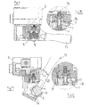
- FIGS. 1 to 3 show one example of the invention in a side view in three successive positions, respectively closed, intermediate and open.
- FIGS. 4 to 6 show the invention device according to the lines of Section AA on FIGS. 1 to 3 respectively.
- FIG. 7 is a sectional view of the invention in the intermediate position in the vertical translation phase.
- FIG. 8 is a perspective view of the open device.
- FIG. 9 shows the extraction device co-acting with a package of ground coffee in the closed position
- FIG. 10 is a detailed view at the level of the water injection part.
- FIG. 11 shows this co-acting in the open position and FIG. 12 is a detailed view of it.
- the invention device is incorporated in a machine particularly suited to the preparation of coffee beverages obtained from the infusion of a substance of the type ground coffee.
- the device is mounted on chassis 3 of the machine by any usual means so as to receive hot water under pressure obtained conventionally from a boiler and a pump.
- This extraction device comprises an infusion chamber which is defined here as being of sufficient volume to receive the ground coffee, packaged or not, and at the level of which hot water injection takes place through the ground coffee.
- the infusion chamber is formed by a fixed part 1 and a moving part 2 .
- the moving part 2 executes the successive operating phases.
- the example shown consists of two infusion chambers ready to operate simultaneously or separately with two packages 6 .
- this example is not restrictive and the invention device may apply to a system using only one package 6 .
- moving part 2 is operated through a lever 20 equipped with a handle 13 by the operator, together with a stirrup type system enclosing moving part 2 .
- Lever 20 is itself being mounted to rotate around axle A relative to frame 3 of the machine.
- the system operating moving part 2 can be more clearly seen on FIGS. 4 to 6 .
- a sliding pivot linkage is formed between lever 20 and moving part 2 so as to generate drive.
- linkage of the sliding pivot is meant a kinematic linkage allowing rotation of the moving part around an axle, itself capable of translation relative to lever 20 .
- the sliding pivot linkage takes the form of a pair of oblong holes 21 formed on two lateral sections of lever 20 so as to co-act with axle C on which moving part 2 is rotatably mounted.
- FIG. 7 shows three rotational mobilities of the invention, that of lever 20 relative to axle A, of moving part 2 relative to axle B and of moving part 2 relative to axle C.
- axle B is formed on a translational element 9 assembled to translate relative to fixed part 1 .
- This translational mobility allows moving part 2 to move towards or away from moving part 1 .
- the fit-up of the two parts, fixed part 1 and moving part 2 only occurs in translation, which creates a better seal and eliminates friction between the two parts.
- the possibility is offered of the moving part moving further away from the fixed part and ensuring greater accessibility of moving part 2 , in particular in the loading and unloading of packages 6 .
- FIGS. 4 to 7 in particular show a translational element 9 in the form of a rod equipped with a vertical section and fitted to translate in a housing 10 until meeting spring 11 with default recall of rod 9 in the remote position relative to fixed part 1 .
- Element 9 also advantageously comprises a longitudinal part 22 extending from the rear part of fixed part 1 towards the front part, appreciably at the level of the underside of moving part 2 .
- Axle of rotation B is positioned advantageously close to longitudinal part 22 .
- Axle B is very slightly offset towards the rear relative to axle C so that in the final phase the rotation of lever 20 generates rotation of moving part 2 .
- the position close to axles B and C ensures great angular displacement between 0 and 90°, especially if manual unloading is required, that is to say more than 90° if it is required to eject by force of gravity.
- element 9 and guiding-housing 10 are formed at the level of the rear face of fixed part 1 .
- a surface on stop 23 is able to co-act with moving part 2 so as to limit its rotational movement, especially during upward movement of moving part 2 towards fixed part 1 .
- Moving part 2 comprises at least one receptacle 5 defining an internal volume accommodating a package 6 .
- Receptacle 5 has an opening in its lower part to create a zone 8 for beverage discharge.
- the shape and the dimensions of receptacle 5 are adapted to the shapes and the dimensions of packages 6 .
- the device is equipped with a pusher 14 capable of being inserted inside the inner volume of receptacle 5 at the end of moving part 2 rotation so as to apply close to the lower part of package 6 and slightly or completely raise it outside the volume of receptacle 5 .
- FIG. 11 An example of a pusher 4 is shown in FIG. 11 during package 6 discharge.
- pusher 14 is created on lever 20 , appreciably towards the rear of the device, the angular displacement of moving part 2 being selected so that pusher 14 is introduced inside the volume of receptacle 5 at the end of rotation.
- FIGS. 9 to 12 also show an example of package 6 and the hot water part of the device acting together.
- package 6 has an end-piece 4 through which hot water is introduced into package 6 , with or without preliminary piercing of end-piece 4 .
- An injection body 17 is also shown in which a central hole allows translational mobility of an injection head capable of bearing on the upper face of end-piece 4 , injection body 17 itself bearing on the upper face of package 6 positioned around end-piece 4 .
- package 6 is particularly well immobilised and sealing can take place, for example, in the form of an o-ring formed between body 17 and the cylindrical part of the lateral surface of end-piece 4 .
- body 17 is surrounded by a crown 18 that can be applied on the upper surface of receptacle 5 .
- Crown 18 is mobile in vertical translation until meeting return means of the type spring 19 .
- end-piece 4 executes vertical translation of injection head 7 leading to the opening of the hot water injection circuit passing into injection head 7 .
- body 17 applies around end-piece 4 so as to maintain and ensure its sealing function.
- crown 18 this is in the retracted position due to the application of the perimeter of receptacle 5 .
- FIG. 11 shows the device in the open position and FIG. 12 more precisely illustrates the rest position of the hot water injection part of the device.
- injection head 7 is deployed in body 17 and is applied against it on meeting spring 16 . Hot water can no longer flow through in this configuration.
- Crown 18 is also in the deployed position at this time.
- lever 20 is positioned using handle 13 in a configuration similar to the one shown, for example, on FIG. 8 for receiving one or more packages 6 in moving part 2 .
- the angular displacement of moving part 2 combined with vertical adjustment ensures excellent opening accessibility of receptacle 5 for introducing packages 6 .
- the sliding pivot linkage causes moving part 2 to pivot on axle B until reaching the straight position by application to the surface of stop 23 .
- moving part 2 then starts a vertical translatory movement until fit up with fixed part 1 through element 9 .
- the position on FIG. 4 is reached via the position on FIG. 5 .
- the hot water injection circuit has been opened by the movement of head 7 acting as a valve in body 17 as shown on FIG. 10 .
- Actuating the machine then causes the hot water to enter package 6 .
- End-piece 4 may have been previously pierced by an appropriate device formed on injection head 7 .
- the beverage is discharged via zone 8 .
- the operator can then apply opposite rotation on lever 20 so as to bring moving part 2 to the open position.
- lever 20 generates firstly downward movement of element 9 corresponding to the position shown on FIGS. 2 , 5 and 7 .
- spring 11 also allows translation in the downward phase so as to produce the rotation of moving part 2 only at the end of travel.
- element 9 reaches a stop formed by a shoulder 12 at the end of guiding-housing 10 .
- the translational movement stops and rotation of moving part 2 around axle B occurs until reaching the maximum angular displacement orientating moving part 2 towards the front of the machine to allow the operator access to package 6 .
- Pusher 14 starts the unloading of package 6 so as to facilitate handling by the operator,
- angular displacement of moving part 2 is such that package 6 is ejected by simple force of gravity.
Abstract
Description
-
- an infusion chamber consisting of a fixed part and a moving part which opens and closes the infusion chamber.
- A lever mounted rotatably relative to an axle (A), able to rotate the moving part relative to axle (B) by a pivot-type linkage sliding between the lever and the moving part,
characterised in that rotational axle (B) of the moving part is situated in an element that is fitted to translate relative to the fixed part in order to bring together or move away the moving part from the fixed part.
-
- device comprising elastic means pushing the element assembled to translate towards a position in which the moving part has been moved away from the fixed part.
- device in which the element assembled in translation includes a rod assembled in a guiding-housing,
- device in which the guiding-housing is formed in the rear face of the fixed part,
- device in which the element assembled to translate consists of a longitudinal part oriented according to the direction of translation and a transversal part on which is situated rotational axle (B) of the moving part,
- device in which the sliding pivot-type linkage is situated between rotation axle (B) of the moving part and rotational axle (A) of the lever,
- device in which the sliding pivot-type linkage consists of an oblong hole formed in the lever which co-acts with drive axle (C) on which the moving part is rotatably fitted,
- device in which the rear face of the fixed part consists of a stop to limit the rotation of the moving part,
- device in which the moving part consists of at least one receptacle for a substance to be infused, the bottom of the receptacle comprising an opening to allow the passage of a pusher into the receptacle volume in order to initiate extraction of the package after use,
- device in which the pusher is formed on the lever in order to pass into the volume of the receptacle at the end of rotation of the moving part,
- device which comprises a body equipped with a head injecting hot water into a packaging of the substance to be infused, the head being mobile and capable of applying or piercing an end-piece formed on the package and the lower surface of the body capable of bearing on the upper face of the package around the end-piece,
- device in which the body is surrounded by a crown bearing elastically on the upper face of a receptacle receiving the package in the moving part, device in which the rotational movement of the moving part is between 45° and 90°.
- device in which the rotational movement of the moving part is greater than 90°.
- 1. Fixed part
- 2. Moving part
- 3. Frame
- 4. End-piece
- 5. Receptacle
- 6. Package
- 7. Injection head
- 8. Beverage ejection zone
- 9. Element assembled in translation
- 10. Guiding-housing
- 11. Spring
- 12. Shoulder
- 13. Handle
- 14. Pusher
- 15. Opening
- 16. Spring
- 17. Injection body
- 18. Crown
- 19. Spring
- 20. Lever
- 21. Oblong hole
- 22. Longitudinal part
- 23. Stop
Claims (15)
Applications Claiming Priority (3)
| Application Number | Priority Date | Filing Date | Title |
|---|---|---|---|
| FR0651981 | 2006-05-31 | ||
| FR0651981A FR2901681B1 (en) | 2006-05-31 | 2006-05-31 | MACHINE FOR MANUFACTURING ESPRESSO COFFEE |
| PCT/EP2007/054644 WO2007137937A1 (en) | 2006-05-31 | 2007-05-14 | Machine for producing espresso-type coffee |
Publications (2)
| Publication Number | Publication Date |
|---|---|
| US20090199720A1 US20090199720A1 (en) | 2009-08-13 |
| US8074560B2 true US8074560B2 (en) | 2011-12-13 |
Family
ID=37680757
Family Applications (1)
| Application Number | Title | Priority Date | Filing Date |
|---|---|---|---|
| US12/302,980 Expired - Fee Related US8074560B2 (en) | 2006-05-31 | 2007-05-14 | Machine for producing espresso-type coffee |
Country Status (7)
| Country | Link |
|---|---|
| US (1) | US8074560B2 (en) |
| EP (1) | EP2020891B1 (en) |
| CN (1) | CN101500457B (en) |
| AT (1) | ATE440528T1 (en) |
| DE (1) | DE602007002194D1 (en) |
| FR (1) | FR2901681B1 (en) |
| WO (1) | WO2007137937A1 (en) |
Cited By (11)
| Publication number | Priority date | Publication date | Assignee | Title |
|---|---|---|---|---|
| US20130224347A1 (en) * | 2010-08-13 | 2013-08-29 | Koninklijke Philips Electronics N.V. | Device, system and method for preparing a beverage from a capsule |
| US20150173560A1 (en) * | 2012-07-30 | 2015-06-25 | Luigi Lavazza S.P.A. | Brewing assembly for a machine for the preparation of beverages using capsules |
| US20150257586A1 (en) * | 2014-03-11 | 2015-09-17 | Starbucks Corporation Dba Starbucks Coffee Company | Single-serve beverage production machine |
| USD760008S1 (en) | 2014-07-08 | 2016-06-28 | Clover Co., Ltd. | Beverage machine |
| US9439532B2 (en) | 2014-03-11 | 2016-09-13 | Starbucks Corporation | Beverage production machines with multi-chambered basket units |
| US9504348B2 (en) | 2014-03-11 | 2016-11-29 | Starbucks Corporation | Cartridge ejection systems and methods for single-serve beverage production machines |
| US20170020328A1 (en) * | 2010-11-11 | 2017-01-26 | Nestec S.A. | Capsule, beverage production machine and system for the preparation of a nutritional product |
| US9968217B2 (en) | 2015-06-16 | 2018-05-15 | Starbucks Corporation | Beverage preparation systems with brew chamber securing mechanisms |
| US10039414B2 (en) | 2014-05-21 | 2018-08-07 | Clover Co., Ltd. | Beverage machine with rotatable brew chamber |
| US10342377B2 (en) | 2015-06-16 | 2019-07-09 | Starbucks Corporation | Beverage preparation systems with adaptable brew chambers |
| US10602874B2 (en) | 2015-06-16 | 2020-03-31 | Starbucks Corporation Dba Starbucks Coffee Company | Beverage preparation systems with brew chamber access mechanisms |
Families Citing this family (8)
| Publication number | Priority date | Publication date | Assignee | Title |
|---|---|---|---|---|
| CN201341791Y (en) * | 2009-01-19 | 2009-11-11 | 广东新宝电器股份有限公司 | Coffee capsule machine |
| IT1398202B1 (en) * | 2010-02-02 | 2013-02-14 | Lavazza Luigi Spa | MACHINE FOR THE PREPARATION OF A BEVERAGE |
| DE102012108653A1 (en) * | 2012-08-20 | 2014-02-20 | Eugster/Frismag Ag Elektrohaushaltgeräte | Brewing device and method for operating a brewing device |
| FR3007959B1 (en) * | 2013-07-05 | 2015-07-31 | Mario Levi | BEVERAGE PREPARATION MACHINE WITH REMOVABLE FILTER HOLDER DEVICE AND SELECTING MEMBER FOR A MODE OF OPERATION OF THE MACHINE |
| PT107334B (en) * | 2013-12-02 | 2020-05-12 | Novadelta - Comércio E Indústria De Cafés, Lda. | SIMPLIFIED PERFORMANCE EXTRACTION DEVICE AND OPERATION PROCESS FOR THIS |
| FR3019980B1 (en) | 2014-04-22 | 2016-05-06 | Unic | DEVICE FOR EXTRACTING AN INFUSER SUBSTANCE |
| ITUB20160433A1 (en) | 2016-02-03 | 2017-08-03 | La Marzocco Srl | Dispensing group for a machine for preparing espresso coffee with front insertion of the filter holder |
| IT201900001623A1 (en) | 2019-02-05 | 2020-08-05 | La Marzocco Srl | Coffee grinder machine with improved dosing system and relative method |
Citations (7)
| Publication number | Priority date | Publication date | Assignee | Title |
|---|---|---|---|---|
| US3384004A (en) * | 1965-11-26 | 1968-05-21 | Hill Shaw Company | Coffeemaker |
| US5638741A (en) * | 1996-05-06 | 1997-06-17 | Cisaria; Salvatore | Group module for coffee machine |
| US20030056655A1 (en) * | 2000-05-04 | 2003-03-27 | Alexandre Kollep | Device for the extraction of a substance having a moveable component |
| FR2849760A1 (en) | 2003-01-15 | 2004-07-16 | Unic | Substance extracting device for producing beverage e.g. espresso-coffee, has connection interface at input of hot water supply and hot water division unit present between infusion chambers where substance to infuse is present |
| US7444927B1 (en) * | 2006-03-01 | 2008-11-04 | Seb S.A. | Brewing machine comprising a device for rejection of the infused product |
| US20090029021A1 (en) * | 2006-02-01 | 2009-01-29 | Handpresso | Appliance for Brewing an Infusion of Coffee or Tea |
| US7531198B2 (en) * | 2003-11-07 | 2009-05-12 | Sgl Italia S.R.L. | Infusion method and device for making a coffee beverage |
Family Cites Families (5)
| Publication number | Priority date | Publication date | Assignee | Title |
|---|---|---|---|---|
| FR547071A (en) * | 1921-02-19 | 1922-11-30 | Improvements to machines for instant coffee making in cups | |
| IT1060679B (en) * | 1976-08-06 | 1982-08-20 | Girolamo Silvestro Di | APPARATUS FOR THE IMPLEMENTATION OF THE COMPLETE CYCLE OF PREPARATION OF MIXED HOT DRINK, OBTAINED FROM SOLUBLE COFFEE POWDER OR OTHER SOLUBLE PRODUCTS |
| DE3843568C1 (en) * | 1988-12-23 | 1989-12-21 | Hgz - Maschinenbau Ag, Daellikon, Zuerich, Ch | |
| CH681685A5 (en) * | 1990-11-02 | 1993-05-14 | Eldom Rothrist Ag | |
| EP1000574A1 (en) * | 1998-11-16 | 2000-05-17 | Societe Des Produits Nestle S.A. | Method and device for extracting a closed cartridge |
-
2006
- 2006-05-31 FR FR0651981A patent/FR2901681B1/en not_active Expired - Fee Related
-
2007
- 2007-05-14 US US12/302,980 patent/US8074560B2/en not_active Expired - Fee Related
- 2007-05-14 EP EP07729096A patent/EP2020891B1/en active Active
- 2007-05-14 CN CN2007800199367A patent/CN101500457B/en active Active
- 2007-05-14 DE DE602007002194T patent/DE602007002194D1/en not_active Expired - Fee Related
- 2007-05-14 AT AT07729096T patent/ATE440528T1/en not_active IP Right Cessation
- 2007-05-14 WO PCT/EP2007/054644 patent/WO2007137937A1/en active Application Filing
Patent Citations (8)
| Publication number | Priority date | Publication date | Assignee | Title |
|---|---|---|---|---|
| US3384004A (en) * | 1965-11-26 | 1968-05-21 | Hill Shaw Company | Coffeemaker |
| US5638741A (en) * | 1996-05-06 | 1997-06-17 | Cisaria; Salvatore | Group module for coffee machine |
| US20030056655A1 (en) * | 2000-05-04 | 2003-03-27 | Alexandre Kollep | Device for the extraction of a substance having a moveable component |
| FR2849760A1 (en) | 2003-01-15 | 2004-07-16 | Unic | Substance extracting device for producing beverage e.g. espresso-coffee, has connection interface at input of hot water supply and hot water division unit present between infusion chambers where substance to infuse is present |
| US20060144243A1 (en) | 2003-01-15 | 2006-07-06 | Jean-Pierre Levi | Substance-extraction device and machine for producing drinks |
| US7531198B2 (en) * | 2003-11-07 | 2009-05-12 | Sgl Italia S.R.L. | Infusion method and device for making a coffee beverage |
| US20090029021A1 (en) * | 2006-02-01 | 2009-01-29 | Handpresso | Appliance for Brewing an Infusion of Coffee or Tea |
| US7444927B1 (en) * | 2006-03-01 | 2008-11-04 | Seb S.A. | Brewing machine comprising a device for rejection of the infused product |
Non-Patent Citations (1)
| Title |
|---|
| International Search Report dated Oct. 26, 2007, from corresponding PCT application. |
Cited By (16)
| Publication number | Priority date | Publication date | Assignee | Title |
|---|---|---|---|---|
| US20130224347A1 (en) * | 2010-08-13 | 2013-08-29 | Koninklijke Philips Electronics N.V. | Device, system and method for preparing a beverage from a capsule |
| US9808112B2 (en) * | 2010-08-13 | 2017-11-07 | Koninklijke Douwe Egberts B.V. | Device, system and method for preparing a beverage from a capsule |
| US20170020328A1 (en) * | 2010-11-11 | 2017-01-26 | Nestec S.A. | Capsule, beverage production machine and system for the preparation of a nutritional product |
| US10070751B2 (en) * | 2010-11-11 | 2018-09-11 | Nestec S.A. | Capsule, beverage production machine and system for the preparation of a nutritional product |
| US20150173560A1 (en) * | 2012-07-30 | 2015-06-25 | Luigi Lavazza S.P.A. | Brewing assembly for a machine for the preparation of beverages using capsules |
| US9888805B2 (en) * | 2012-07-30 | 2018-02-13 | Luigi Lavazza S.P.A. | Brewing assembly for a machine for the preparation of beverages using capsules |
| US9439532B2 (en) | 2014-03-11 | 2016-09-13 | Starbucks Corporation | Beverage production machines with multi-chambered basket units |
| US9504348B2 (en) | 2014-03-11 | 2016-11-29 | Starbucks Corporation | Cartridge ejection systems and methods for single-serve beverage production machines |
| US9999315B2 (en) | 2014-03-11 | 2018-06-19 | Starbucks Corporation | Beverage production methods with multi chambered basket units |
| US20150257586A1 (en) * | 2014-03-11 | 2015-09-17 | Starbucks Corporation Dba Starbucks Coffee Company | Single-serve beverage production machine |
| US10039414B2 (en) | 2014-05-21 | 2018-08-07 | Clover Co., Ltd. | Beverage machine with rotatable brew chamber |
| USD760008S1 (en) | 2014-07-08 | 2016-06-28 | Clover Co., Ltd. | Beverage machine |
| USD812971S1 (en) | 2014-07-08 | 2018-03-20 | Clover Co., Ltd. | Portion of a beverage machine |
| US9968217B2 (en) | 2015-06-16 | 2018-05-15 | Starbucks Corporation | Beverage preparation systems with brew chamber securing mechanisms |
| US10342377B2 (en) | 2015-06-16 | 2019-07-09 | Starbucks Corporation | Beverage preparation systems with adaptable brew chambers |
| US10602874B2 (en) | 2015-06-16 | 2020-03-31 | Starbucks Corporation Dba Starbucks Coffee Company | Beverage preparation systems with brew chamber access mechanisms |
Also Published As
| Publication number | Publication date |
|---|---|
| EP2020891A1 (en) | 2009-02-11 |
| ATE440528T1 (en) | 2009-09-15 |
| CN101500457B (en) | 2011-02-02 |
| FR2901681A1 (en) | 2007-12-07 |
| EP2020891B1 (en) | 2009-08-26 |
| CN101500457A (en) | 2009-08-05 |
| DE602007002194D1 (en) | 2009-10-08 |
| FR2901681B1 (en) | 2008-07-25 |
| US20090199720A1 (en) | 2009-08-13 |
| WO2007137937A1 (en) | 2007-12-06 |
Similar Documents
| Publication | Publication Date | Title |
|---|---|---|
| US8074560B2 (en) | Machine for producing espresso-type coffee | |
| KR101691683B1 (en) | Beverage preparation device having a closing mechanism with force demultiplying means | |
| CN103169378B (en) | Beverage brewing unit | |
| EP1480540B1 (en) | Device for producing beverage by infusion | |
| US20100189859A1 (en) | Device and process for brewing a drink | |
| EP2679120B1 (en) | Appliance and capsule for preparing a beverage | |
| RU2533111C2 (en) | Beverage brewing module with hydraulic closure system | |
| JP2015533564A (en) | Multi-size cartridge extraction unit with slide | |
| CN106132254A (en) | Beverage brewing unit especially for the machine preparing beverage from capsule | |
| MX2015001933A (en) | Brewing apparatus and method for operating a brewing apparatus. | |
| JP2012515007A (en) | Transportable and compact device for preparing beverages | |
| EP3030117B1 (en) | Horizontal unit for making beverages using capsules containing powdered food substances | |
| US10750897B2 (en) | Device for extracting a substance to be brewed |
Legal Events
| Date | Code | Title | Description |
|---|---|---|---|
| AS | Assignment |
Owner name: UNIC (SAS), FRANCE Free format text: ASSIGNMENT OF ASSIGNORS INTEREST;ASSIGNORS:LEVI, MARIO;LEVI, JEAN-PIERRE;REEL/FRAME:021906/0199 Effective date: 20081107 |
|
| ZAAA | Notice of allowance and fees due |
Free format text: ORIGINAL CODE: NOA |
|
| ZAAB | Notice of allowance mailed |
Free format text: ORIGINAL CODE: MN/=. |
|
| STCF | Information on status: patent grant |
Free format text: PATENTED CASE |
|
| FPAY | Fee payment |
Year of fee payment: 4 |
|
| MAFP | Maintenance fee payment |
Free format text: PAYMENT OF MAINTENANCE FEE, 8TH YR, SMALL ENTITY (ORIGINAL EVENT CODE: M2552); ENTITY STATUS OF PATENT OWNER: SMALL ENTITY Year of fee payment: 8 |
|
| FEPP | Fee payment procedure |
Free format text: MAINTENANCE FEE REMINDER MAILED (ORIGINAL EVENT CODE: REM.); ENTITY STATUS OF PATENT OWNER: SMALL ENTITY |
|
| LAPS | Lapse for failure to pay maintenance fees |
Free format text: PATENT EXPIRED FOR FAILURE TO PAY MAINTENANCE FEES (ORIGINAL EVENT CODE: EXP.); ENTITY STATUS OF PATENT OWNER: SMALL ENTITY |
|
| STCH | Information on status: patent discontinuation |
Free format text: PATENT EXPIRED DUE TO NONPAYMENT OF MAINTENANCE FEES UNDER 37 CFR 1.362 |
|
| FP | Lapsed due to failure to pay maintenance fee |
Effective date: 20231213 |