US9765772B2 - Liquid gear pump - Google Patents

Liquid gear pump Download PDF

Info

Publication number
US9765772B2
US9765772B2 US13/486,506 US201213486506A US9765772B2 US 9765772 B2 US9765772 B2 US 9765772B2 US 201213486506 A US201213486506 A US 201213486506A US 9765772 B2 US9765772 B2 US 9765772B2
Authority
US
United States
Prior art keywords
pump
ring wall
gear
cover plate
pump chamber
Prior art date
Legal status (The legal status is an assumption and is not a legal conclusion. Google has not performed a legal analysis and makes no representation as to the accuracy of the status listed.)
Active
Application number
US13/486,506
Other versions
US20120305603A1 (en
Inventor
Lo Ching KWOK
Chun Fa Wu
Current Assignee (The listed assignees may be inaccurate. Google has not performed a legal analysis and makes no representation or warranty as to the accuracy of the list.)
Johnson Electric International AG
Original Assignee
Johnson Electric SA
Priority date (The priority date is an assumption and is not a legal conclusion. Google has not performed a legal analysis and makes no representation as to the accuracy of the date listed.)
Filing date
Publication date
Application filed by Johnson Electric SA filed Critical Johnson Electric SA
Assigned to JOHNSON ELECTRIC S.A. reassignment JOHNSON ELECTRIC S.A. ASSIGNMENT OF ASSIGNORS INTEREST (SEE DOCUMENT FOR DETAILS). Assignors: KWOK, LO CHING, WU, CHUN FA
Publication of US20120305603A1 publication Critical patent/US20120305603A1/en
Application granted granted Critical
Publication of US9765772B2 publication Critical patent/US9765772B2/en
Assigned to Johnson Electric International AG reassignment Johnson Electric International AG MERGER (SEE DOCUMENT FOR DETAILS). Assignors: JOHNSON ELECTRIC S.A.
Active legal-status Critical Current
Anticipated expiration legal-status Critical

Links

Images

Classifications

    • FMECHANICAL ENGINEERING; LIGHTING; HEATING; WEAPONS; BLASTING
    • F04POSITIVE - DISPLACEMENT MACHINES FOR LIQUIDS; PUMPS FOR LIQUIDS OR ELASTIC FLUIDS
    • F04CROTARY-PISTON, OR OSCILLATING-PISTON, POSITIVE-DISPLACEMENT MACHINES FOR LIQUIDS; ROTARY-PISTON, OR OSCILLATING-PISTON, POSITIVE-DISPLACEMENT PUMPS
    • F04C2/00Rotary-piston machines or pumps
    • F04C2/08Rotary-piston machines or pumps of intermeshing-engagement type, i.e. with engagement of co-operating members similar to that of toothed gearing
    • F04C2/082Details specially related to intermeshing engagement type machines or pumps
    • F04C2/084Toothed wheels
    • FMECHANICAL ENGINEERING; LIGHTING; HEATING; WEAPONS; BLASTING
    • F04POSITIVE - DISPLACEMENT MACHINES FOR LIQUIDS; PUMPS FOR LIQUIDS OR ELASTIC FLUIDS
    • F04CROTARY-PISTON, OR OSCILLATING-PISTON, POSITIVE-DISPLACEMENT MACHINES FOR LIQUIDS; ROTARY-PISTON, OR OSCILLATING-PISTON, POSITIVE-DISPLACEMENT PUMPS
    • F04C2/00Rotary-piston machines or pumps
    • F04C2/08Rotary-piston machines or pumps of intermeshing-engagement type, i.e. with engagement of co-operating members similar to that of toothed gearing
    • F04C2/12Rotary-piston machines or pumps of intermeshing-engagement type, i.e. with engagement of co-operating members similar to that of toothed gearing of other than internal-axis type
    • F04C2/14Rotary-piston machines or pumps of intermeshing-engagement type, i.e. with engagement of co-operating members similar to that of toothed gearing of other than internal-axis type with toothed rotary pistons
    • F04C2/18Rotary-piston machines or pumps of intermeshing-engagement type, i.e. with engagement of co-operating members similar to that of toothed gearing of other than internal-axis type with toothed rotary pistons with similar tooth forms
    • FMECHANICAL ENGINEERING; LIGHTING; HEATING; WEAPONS; BLASTING
    • F04POSITIVE - DISPLACEMENT MACHINES FOR LIQUIDS; PUMPS FOR LIQUIDS OR ELASTIC FLUIDS
    • F04CROTARY-PISTON, OR OSCILLATING-PISTON, POSITIVE-DISPLACEMENT MACHINES FOR LIQUIDS; ROTARY-PISTON, OR OSCILLATING-PISTON, POSITIVE-DISPLACEMENT PUMPS
    • F04C2/00Rotary-piston machines or pumps
    • F04C2/08Rotary-piston machines or pumps of intermeshing-engagement type, i.e. with engagement of co-operating members similar to that of toothed gearing
    • F04C2/082Details specially related to intermeshing engagement type machines or pumps
    • F04C2/086Carter
    • FMECHANICAL ENGINEERING; LIGHTING; HEATING; WEAPONS; BLASTING
    • F04POSITIVE - DISPLACEMENT MACHINES FOR LIQUIDS; PUMPS FOR LIQUIDS OR ELASTIC FLUIDS
    • F04CROTARY-PISTON, OR OSCILLATING-PISTON, POSITIVE-DISPLACEMENT MACHINES FOR LIQUIDS; ROTARY-PISTON, OR OSCILLATING-PISTON, POSITIVE-DISPLACEMENT PUMPS
    • F04C2220/00Application
    • F04C2220/24Application for metering throughflow
    • FMECHANICAL ENGINEERING; LIGHTING; HEATING; WEAPONS; BLASTING
    • F05INDEXING SCHEMES RELATING TO ENGINES OR PUMPS IN VARIOUS SUBCLASSES OF CLASSES F01-F04
    • F05CINDEXING SCHEME RELATING TO MATERIALS, MATERIAL PROPERTIES OR MATERIAL CHARACTERISTICS FOR MACHINES, ENGINES OR PUMPS OTHER THAN NON-POSITIVE-DISPLACEMENT MACHINES OR ENGINES
    • F05C2225/00Synthetic polymers, e.g. plastics; Rubber

Definitions

  • This invention relates to a liquid pump and in particular, to a liquid gear pump which is especially suitable for automatic beverage dispensers.
  • Gear pumps are popular for precise transfer and metering applications such as automatic beverage dispensers.
  • a typical gear pump includes a pump housing defining a chamber, two gears received in the chamber, and a liquid inlet and a liquid outlet which are in fluid communication with the chamber.
  • One of the two gears is a driving gear driven by a motor and the other one is an idle gear driven by the driving gear.
  • the two gears rotate against each other so as to create the pump action. Liquid entering the pump inlet is drawn into the space between the inner surface of the chamber and teeth of the rotating gears and then is forced through the pump outlet under pressure.
  • the flow rate of the liquid can be accurately controlled by the rotational speed of the gears, which can be regulated by varying the speed of the motor.
  • the pumping of hot liquid is required.
  • the gears of the gear pump are immersed in the hot liquid, the gears expand creating excessive engagement between the two gears leading to excessive wear or jamming of the gears, neither of which is desired. This can be avoided by appropriate sizing of the gears to allow for the expansion, however this means that the pump does not operate efficiently with cold or warm liquids.
  • the gear pump is in direct contact with a liquid for human consumption, the pump must satisfy the requirements of certain food safety standards.
  • the present invention provides a liquid gear pump, comprising: a gear pump assembly; and an electric motor having a motor shaft, the gear pump assembly comprising a pump housing which defines a pump chamber, an inlet and an outlet in fluid communication with the pump chamber, and a driving gear and an idle gear disposed within the pump chamber, the driving gear being driven by the motor shaft, the idle gear being supported on an idle shaft and engaged with the driving gear; wherein the driving gear and the idle gear are made of a material with a main component of polyphenylene sulfide.
  • the material contains 40 to 80 percent by weight of polyphenylene sulfide.
  • the driving gear and the idle gear are made of a material with main components of polyphenylene sulfide and glass fiber.
  • the material contains 40 to 80 percent by weight of polyphenylene sulfide and 20 to 60 percent by weight of glass fiber.
  • the pump housing is made of a material with a main component of polyphthalamide, polyphenylene sulfide, or polyetherimide.
  • the idle shaft is made of ceramic.
  • the gear pump assembly further comprises an outer cover plate fixed to the pump housing at one side away from the motor, an intermediate plate fixed to the pump housing at one side near the motor, and a mounting plate mounting the gear pump assembly to the motor.
  • a shaft seal is sealingly sleeved on the motor shaft to prevent the liquid from leaking out of the pump chamber along the motor shaft.
  • the gear pump assembly further comprises an inner cover plate closing the pump chamber and a sealing gasket sealing the pump chamber to the inner cover plate.
  • the present invention provides a beverage dispenser comprising: an user interface for triggering dispensing of a beverage; a controller for controlling the dispensing of the beverage; a liquid source; a liquid supply line fluidly connected to the liquid source; and a liquid gear pump connected to the liquid supply line, for pumping the liquid from the liquid source to a dispenser point for dispensing the beverage, comprising a gear pump assembly and an electric motor having a motor shaft, the gear pump assembly comprising a pump housing which defines a pump chamber, an inlet and an outlet in fluid communication with the pump chamber, and a driving gear and an idle gear disposed within the pump chamber, the driving gear being driven by the motor shaft, the idle gear being supported on an idle shaft and engaged with the driving gear, wherein the driving gear and the idle gear are made of a material with a main component of polyphenylene sulfide.
  • the material contains 40 to 80 percent by weight of polyphenylene sulfide.
  • the driving gear and the idle gear are made of a material with main components of polyphenylene sulfide and glass fiber.
  • the material contains 40 to 80 percent by weight of polyphenylene sulfide and 20 to 60 percent by weight of glass fiber.
  • the pump housing is made of a material with a main component of polyphthalamide, polyphenylene sulfide, or polyetherimide.
  • the idle shaft is made of ceramic.
  • the gear pump assembly further comprises an outer cover plate fixed to the pump housing at one side away from the motor, an intermediate plate fixed to the pump housing at one side near the motor, and a mounting plate mounting the gear pump assembly to the motor.
  • a shaft seal is sealingly sleeved on the motor shaft to prevent the liquid from leaking out of the pump chamber along the motor shaft.
  • the gear pump assembly further comprises an inner cover plate closing the pump chamber and a sealing gasket sealing the pump chamber to the inner cover plate.
  • the driving gear and the idle gear are not only able to fulfill requirements for food safety standards, but have a good high temperature resistance, wearing resistance and acid resistance as well. PPS is also approved for use with food.
  • FIG. 1 is a schematic diagram of an automatic beverage dispenser incorporating a liquid gear pump in accordance with a preferred embodiment of the present invention
  • FIG. 2 is an assembled view of the liquid gear pump of FIG. 1 ;
  • FIG. 3 is an exploded view of the liquid gear pump of FIG. 2 ;
  • FIG. 4 is a sectional view of a gear pump assembly being a part of the liquid gear pump of FIG. 2 ;
  • FIG. 5 is an assembled view of the gear pump assembly of FIG. 4 , with inner and outer cover plates and a sealing gasket omitted to show the inner structure of the gear pump assembly.
  • FIG. 1 is a schematic diagram of an automatic beverage dispenser 10 incorporating a liquid gear pump in accordance with a preferred embodiment of the present invention.
  • the beverage dispenser 10 comprises an user interface 12 , which may be a press button, for triggering the dispensing of a beverage, a controller 14 for controlling the dispensing of the beverage, a liquid supply line 16 connecting a liquid source 18 to a liquid gear pump 20 for pumping the liquid from the liquid source 18 to a dispenser point 22 for dispensing the beverage, which may be the liquid itself or a mixture of the liquid and some other beverage material such as coffee powder.
  • the gear pump 20 comprises a gear pump assembly 30 driven by an electric motor 32 .
  • the motor has a motor shaft 34 .
  • the gear pump assembly 30 comprises a molded pump housing 36 , a driving gear 38 coupled to the motor shaft 34 of the motor 32 , an idle gear 40 rotatable mounted to an idle shaft 70 and in mesh with the driving gear 38 , an outer cover plate 42 fixed to the pump housing 36 on a side remote from the motor 32 , an intermediate plate 44 fixed to the pump housing 36 on the side adjacent the motor 32 , and a mounting plate 46 mounting the gear pump assembly 30 to the motor 32 .
  • the electric motor 32 has two electrical terminals 48 for electrically connecting to an external power supply.
  • the motor shaft 34 of the motor is rotatably supported by bearings 50 at both ends of the motor 32 and passes through the mounting plate 46 , the intermediate plate 44 , and the pump housing 36 to drive the driving gear 38 .
  • the motor 32 is a direct current motor.
  • the motor shaft 34 may also extend from the motor at the end remote from the pump assembly to drive, for example, a rotation or position sensor (not shown) for monitoring operation of the pump.
  • the pump housing 36 , the outer cover plate 42 , the intermediate plate 44 and the mounting plate 46 have the same peripheral configuration in roughly rectangular shape with the longer edges parallel and the shorter edges convex and are all held together by four screws 52 engaging mounting holes 54 at the four corners thereof.
  • the mounting plate 46 is fixed to the motor 32 via screws 56 .
  • the pump housing 36 defines a pump chamber 58 that is open on one side remote from the motor 32 .
  • the pump chamber 58 is oval shaped and located nearer one of the convex sides of the pump housing 36 .
  • An inlet 60 and an outlet 62 oppositely and outwardly extend from the side wall 64 of the pump chamber 58 and are in fluid communication with the pump chamber 58 .
  • a reinforcing rib 66 is integrally molded as part of the pump housing 36 at a position near the other convex edge of the pump housing 36 to improve the mechanical strength of the pump housing.
  • the driving gear 38 and the idle gear 40 are received in the pump chamber 58 with a gap 39 left between radial tips 43 of teeth of the gears 38 , 40 and the inner surface of the pump chamber 58 .
  • the gap 39 must be closely controlled as this directly affects the efficiency of the pump. If the gap 39 is too small there will be too much friction between the gears and the wall of the pump chamber. If the gap 39 is too big there will be poor sealing between the gears and the wall of the pump chamber allowing too much recirculation or cross flow of the liquid resulting in low pressure and low flow rate.
  • the operating principle of a gear pump is well known.
  • the driving gear 38 is coupled to an end of the motor shaft 34 that passes through a bottom wall 68 of the pump chamber 58 , so as to rotate with the motor shaft 34 .
  • the idle gear 40 is rotatably supported by the idle shaft 70 , which is supported in a boss 72 projecting away from the bottom wall 68 .
  • a first shoulder 74 is provided at an inner side of a first ring wall 76 .
  • An inner cover plate 78 closing the opening of the pump chamber 58 is seated on the first shoulder 74 and matches the inner peripheral surface of the first ring wall 76 .
  • the inner cover plate forms the upper surface of the pump chamber against which the gears 38 , 40 , rub.
  • the peripheral edge of the inner cover plate 78 is axially aligned with the inner peripheral surface of the first ring wall 76 .
  • the upper surface of the first ring wall 76 forms a second shoulder 80 .
  • a sealing gasket 82 is seated on the second shoulder 80 and matches the inner peripheral surface of a second ring wall 84 surrounding the first ring wall 76 .
  • the sealing gasket 82 covers the join between the inner cover plate 78 and the second shoulder 80 so as to prevent the liquid from leaking out of the pump chamber 58 from the join.
  • the outer cover plate 42 compresses the sealing gasket 82 against the inner cover plate 78 and the first ring wall 76 . It should be noted that in FIG.
  • the mounting plate 46 has a circular opening 90 and the intermediate plate 44 has a keyhole shaped opening with a larger area 92 and a smaller area 94 .
  • a bearing holder 96 for supporting one of the bearings 50 is received in the circular opening 90 and the larger area 92 .
  • the boss 72 is received in the smaller area 94 .
  • the driving gear 38 and the idle gear 40 are made of a material with main components of polyphenylene sulfide (PPS) and glass fiber.
  • the material may contain 40 to 80 percent by weight of PPS and 20 to 60 percent by weight of glass fiber.
  • PPS polyphenylene sulfide
  • the driving gear 38 and the idle gear 40 are immersed in the liquid.
  • PPS has excellent low water absorption characteristics, no expansion deformation will occur in the driving gear 38 and the idle gear 40 even if they are immersed in the hot liquid for a long period of time. Therefore, the excessive engagement between the driving gear 38 and the idle gear 40 can be avoided.
  • the introduction of the glass fiber gives the driving gear 38 and the idle gear 40 better mechanical strength.
  • the two gears 38 , 40 are not only able to fulfill requirements for food safety standards, but have a good high temperature resistance, water ingress resistance, wear resistance and acid resistance as well.
  • the pump housing 36 is made of a material with a main component of polyphthalamide (PPA). Besides its low-cost advantage, PPA has a desired low water absorption characteristics. Thus no significant expansion deformation will occur in the pump housing 36 and a stable fluid flow rate can be assured.
  • PPA polyphthalamide
  • the sealing gasket 82 is made of silicon rubber.
  • the shaft seal 86 may be made of a mixture of fluoroelastomer (FKM) and polytetrafluoroethylene (PTFE).
  • the inner cover plate 78 , the outer cover plate 42 and the intermediate plate 44 are made of stainless steel.
  • the mounting plate 46 may be made of plastics material.
  • the motor shaft 34 may be made of stainless steel and the idle shaft 70 may be a ceramic material.
  • the pump housing 36 may be made of a material with a main component of PPS or polyetherimide (PEI).
  • PPS polyetherimide

Abstract

A liquid gear pump includes a gear pump assembly and an electric motor with an motor shaft. The gear pump assembly includes a pump housing which defines a pump chamber, an inlet and an outlet which are in fluid communication with the pump chamber, and a driving gear and an idle gear which are received in the pump chamber. The driving gear is driven by the motor shaft. The idle gear is supported on an idle shaft and engaged with the driving gear. The driving gear and the idle gear are made of a material with a main component of PPS.

Description

CROSS REFERENCE TO RELATED APPLICATIONS
This non-provisional patent application claims priority under 35 U.S.C. §119(a) from Patent Application No. 201110146710.1 filed in The People's Republic of China on Jun. 1, 2011.
FIELD OF THE INVENTION
This invention relates to a liquid pump and in particular, to a liquid gear pump which is especially suitable for automatic beverage dispensers.
BACKGROUND OF THE INVENTION
Gear pumps are popular for precise transfer and metering applications such as automatic beverage dispensers. A typical gear pump includes a pump housing defining a chamber, two gears received in the chamber, and a liquid inlet and a liquid outlet which are in fluid communication with the chamber. One of the two gears is a driving gear driven by a motor and the other one is an idle gear driven by the driving gear. The two gears rotate against each other so as to create the pump action. Liquid entering the pump inlet is drawn into the space between the inner surface of the chamber and teeth of the rotating gears and then is forced through the pump outlet under pressure. The flow rate of the liquid can be accurately controlled by the rotational speed of the gears, which can be regulated by varying the speed of the motor.
In some beverage dispensers the pumping of hot liquid is required. As the gears of the gear pump are immersed in the hot liquid, the gears expand creating excessive engagement between the two gears leading to excessive wear or jamming of the gears, neither of which is desired. This can be avoided by appropriate sizing of the gears to allow for the expansion, however this means that the pump does not operate efficiently with cold or warm liquids. Also, as the gear pump is in direct contact with a liquid for human consumption, the pump must satisfy the requirements of certain food safety standards.
SUMMARY OF THE INVENTION
Accordingly, in one aspect thereof, the present invention provides a liquid gear pump, comprising: a gear pump assembly; and an electric motor having a motor shaft, the gear pump assembly comprising a pump housing which defines a pump chamber, an inlet and an outlet in fluid communication with the pump chamber, and a driving gear and an idle gear disposed within the pump chamber, the driving gear being driven by the motor shaft, the idle gear being supported on an idle shaft and engaged with the driving gear; wherein the driving gear and the idle gear are made of a material with a main component of polyphenylene sulfide.
Preferably, the material contains 40 to 80 percent by weight of polyphenylene sulfide.
Preferably, the driving gear and the idle gear are made of a material with main components of polyphenylene sulfide and glass fiber.
Preferably, the material contains 40 to 80 percent by weight of polyphenylene sulfide and 20 to 60 percent by weight of glass fiber.
Preferably, the pump housing is made of a material with a main component of polyphthalamide, polyphenylene sulfide, or polyetherimide.
Preferably, the idle shaft is made of ceramic.
Preferably, the gear pump assembly further comprises an outer cover plate fixed to the pump housing at one side away from the motor, an intermediate plate fixed to the pump housing at one side near the motor, and a mounting plate mounting the gear pump assembly to the motor.
Preferably, a shaft seal is sealingly sleeved on the motor shaft to prevent the liquid from leaking out of the pump chamber along the motor shaft.
Preferably, the gear pump assembly further comprises an inner cover plate closing the pump chamber and a sealing gasket sealing the pump chamber to the inner cover plate.
According to a second aspect, the present invention provides a beverage dispenser comprising: an user interface for triggering dispensing of a beverage; a controller for controlling the dispensing of the beverage; a liquid source; a liquid supply line fluidly connected to the liquid source; and a liquid gear pump connected to the liquid supply line, for pumping the liquid from the liquid source to a dispenser point for dispensing the beverage, comprising a gear pump assembly and an electric motor having a motor shaft, the gear pump assembly comprising a pump housing which defines a pump chamber, an inlet and an outlet in fluid communication with the pump chamber, and a driving gear and an idle gear disposed within the pump chamber, the driving gear being driven by the motor shaft, the idle gear being supported on an idle shaft and engaged with the driving gear, wherein the driving gear and the idle gear are made of a material with a main component of polyphenylene sulfide.
Preferably, the material contains 40 to 80 percent by weight of polyphenylene sulfide.
Preferably, the driving gear and the idle gear are made of a material with main components of polyphenylene sulfide and glass fiber.
Preferably, the material contains 40 to 80 percent by weight of polyphenylene sulfide and 20 to 60 percent by weight of glass fiber.
Preferably, the pump housing is made of a material with a main component of polyphthalamide, polyphenylene sulfide, or polyetherimide.
Preferably, the idle shaft is made of ceramic.
Preferably, the gear pump assembly further comprises an outer cover plate fixed to the pump housing at one side away from the motor, an intermediate plate fixed to the pump housing at one side near the motor, and a mounting plate mounting the gear pump assembly to the motor.
Preferably, a shaft seal is sealingly sleeved on the motor shaft to prevent the liquid from leaking out of the pump chamber along the motor shaft.
Preferably, the gear pump assembly further comprises an inner cover plate closing the pump chamber and a sealing gasket sealing the pump chamber to the inner cover plate.
As PPS has excellent low water absorption capacity, no expansion deformation will happen to the driving gear and the idle gear even if they are immersed in the hot liquid for a long time. Therefore, the excessive engagement between the driving gear and the idle gear can be avoided. On the other hand, the introduction of the glass fiber brings the driving gear and the idle gear a better mechanical strength. Summarily, the driving gear and the idle gear are not only able to fulfill requirements for food safety standards, but have a good high temperature resistance, wearing resistance and acid resistance as well. PPS is also approved for use with food.
BRIEF DESCRIPTION OF THE DRAWINGS
A preferred embodiment of the invention will now be described, by way of example only, with reference to figures of the accompanying drawings. In the figures, identical structures, elements or parts that appear in more than one figure are generally labeled with a same reference numeral in all the figures in which they appear. Dimensions of components and features shown in the figures are generally chosen for convenience and clarity of presentation and are not necessarily shown to scale. The figures are listed below.
FIG. 1 is a schematic diagram of an automatic beverage dispenser incorporating a liquid gear pump in accordance with a preferred embodiment of the present invention;
FIG. 2 is an assembled view of the liquid gear pump of FIG. 1;
FIG. 3 is an exploded view of the liquid gear pump of FIG. 2;
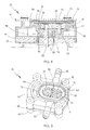
FIG. 4 is a sectional view of a gear pump assembly being a part of the liquid gear pump of FIG. 2; and
FIG. 5 is an assembled view of the gear pump assembly of FIG. 4, with inner and outer cover plates and a sealing gasket omitted to show the inner structure of the gear pump assembly.
DETAILED DESCRIPTION OF THE PREFERRED EMBODIMENTS
FIG. 1 is a schematic diagram of an automatic beverage dispenser 10 incorporating a liquid gear pump in accordance with a preferred embodiment of the present invention. The beverage dispenser 10 comprises an user interface 12, which may be a press button, for triggering the dispensing of a beverage, a controller 14 for controlling the dispensing of the beverage, a liquid supply line 16 connecting a liquid source 18 to a liquid gear pump 20 for pumping the liquid from the liquid source 18 to a dispenser point 22 for dispensing the beverage, which may be the liquid itself or a mixture of the liquid and some other beverage material such as coffee powder.
The gear pump, or parts thereof, is shown in detail in FIGS. 2 to 5. The gear pump 20 comprises a gear pump assembly 30 driven by an electric motor 32. The motor has a motor shaft 34. The gear pump assembly 30 comprises a molded pump housing 36, a driving gear 38 coupled to the motor shaft 34 of the motor 32, an idle gear 40 rotatable mounted to an idle shaft 70 and in mesh with the driving gear 38, an outer cover plate 42 fixed to the pump housing 36 on a side remote from the motor 32, an intermediate plate 44 fixed to the pump housing 36 on the side adjacent the motor 32, and a mounting plate 46 mounting the gear pump assembly 30 to the motor 32.
The electric motor 32 has two electrical terminals 48 for electrically connecting to an external power supply. The motor shaft 34 of the motor is rotatably supported by bearings 50 at both ends of the motor 32 and passes through the mounting plate 46, the intermediate plate 44, and the pump housing 36 to drive the driving gear 38. Preferably, the motor 32 is a direct current motor. The motor shaft 34 may also extend from the motor at the end remote from the pump assembly to drive, for example, a rotation or position sensor (not shown) for monitoring operation of the pump.
The pump housing 36, the outer cover plate 42, the intermediate plate 44 and the mounting plate 46 have the same peripheral configuration in roughly rectangular shape with the longer edges parallel and the shorter edges convex and are all held together by four screws 52 engaging mounting holes 54 at the four corners thereof. The mounting plate 46 is fixed to the motor 32 via screws 56.
As more clearly shown in FIG. 5, the pump housing 36 defines a pump chamber 58 that is open on one side remote from the motor 32. The pump chamber 58 is oval shaped and located nearer one of the convex sides of the pump housing 36. An inlet 60 and an outlet 62 oppositely and outwardly extend from the side wall 64 of the pump chamber 58 and are in fluid communication with the pump chamber 58. A reinforcing rib 66 is integrally molded as part of the pump housing 36 at a position near the other convex edge of the pump housing 36 to improve the mechanical strength of the pump housing.
The driving gear 38 and the idle gear 40 are received in the pump chamber 58 with a gap 39 left between radial tips 43 of teeth of the gears 38, 40 and the inner surface of the pump chamber 58. The gap 39 must be closely controlled as this directly affects the efficiency of the pump. If the gap 39 is too small there will be too much friction between the gears and the wall of the pump chamber. If the gap 39 is too big there will be poor sealing between the gears and the wall of the pump chamber allowing too much recirculation or cross flow of the liquid resulting in low pressure and low flow rate. The operating principle of a gear pump is well known. The driving gear 38 is coupled to an end of the motor shaft 34 that passes through a bottom wall 68 of the pump chamber 58, so as to rotate with the motor shaft 34. The idle gear 40 is rotatably supported by the idle shaft 70, which is supported in a boss 72 projecting away from the bottom wall 68. When the motor 32 is operating, the driving gear 38 and the idle gear 40 rotate against each other to create the pumping action so that the liquid is drawn into the pump chamber 58 from the inlet 60 and then is forced through the outlet 62 under pressure.
At the top or open side of the pump chamber 58, a first shoulder 74 is provided at an inner side of a first ring wall 76. An inner cover plate 78 closing the opening of the pump chamber 58 is seated on the first shoulder 74 and matches the inner peripheral surface of the first ring wall 76. The inner cover plate forms the upper surface of the pump chamber against which the gears 38, 40, rub. The peripheral edge of the inner cover plate 78 is axially aligned with the inner peripheral surface of the first ring wall 76. The upper surface of the first ring wall 76 forms a second shoulder 80. A sealing gasket 82 is seated on the second shoulder 80 and matches the inner peripheral surface of a second ring wall 84 surrounding the first ring wall 76. The sealing gasket 82 covers the join between the inner cover plate 78 and the second shoulder 80 so as to prevent the liquid from leaking out of the pump chamber 58 from the join. The outer cover plate 42 compresses the sealing gasket 82 against the inner cover plate 78 and the first ring wall 76. It should be noted that in FIG. 5, the outer cover plate, the sealing gasket and the inner cover plate have been omitted to show the driving gear 38 and the idle gear 40 located within the pump chamber 58 A shaft seal 86 sealingly sleeved on the motor shaft 34 is received in a recess 88 formed in the bottom wall 68 of the pump chamber 58 to seal the entry of the motor shaft into the pump chamber to prevent the liquid from leaking out between the pump chamber 58 and the motor shaft 34.
The mounting plate 46 has a circular opening 90 and the intermediate plate 44 has a keyhole shaped opening with a larger area 92 and a smaller area 94. A bearing holder 96 for supporting one of the bearings 50 is received in the circular opening 90 and the larger area 92. The boss 72 is received in the smaller area 94.
Preferably, the driving gear 38 and the idle gear 40 are made of a material with main components of polyphenylene sulfide (PPS) and glass fiber. The material may contain 40 to 80 percent by weight of PPS and 20 to 60 percent by weight of glass fiber. During operation of the gear pump, the driving gear 38 and the idle gear 40 are immersed in the liquid. As PPS has excellent low water absorption characteristics, no expansion deformation will occur in the driving gear 38 and the idle gear 40 even if they are immersed in the hot liquid for a long period of time. Therefore, the excessive engagement between the driving gear 38 and the idle gear 40 can be avoided. The introduction of the glass fiber gives the driving gear 38 and the idle gear 40 better mechanical strength. Summarily, the two gears 38, 40 are not only able to fulfill requirements for food safety standards, but have a good high temperature resistance, water ingress resistance, wear resistance and acid resistance as well.
Preferably, the pump housing 36 is made of a material with a main component of polyphthalamide (PPA). Besides its low-cost advantage, PPA has a desired low water absorption characteristics. Thus no significant expansion deformation will occur in the pump housing 36 and a stable fluid flow rate can be assured.
Preferably, the sealing gasket 82 is made of silicon rubber. The shaft seal 86 may be made of a mixture of fluoroelastomer (FKM) and polytetrafluoroethylene (PTFE).
Preferably, the inner cover plate 78, the outer cover plate 42 and the intermediate plate 44 are made of stainless steel. The mounting plate 46 may be made of plastics material. The motor shaft 34 may be made of stainless steel and the idle shaft 70 may be a ceramic material. Making the outer cover plate 42 and the intermediate plate 44 out of a rigid material such as metal, helps to maintain the flatness of the pump housing needed for the efficient operation of the gear pump. Using stainless steel extents the product life by resisting rust as well as being suitable for contact with food.
In the description and claims of the present application, each of the verbs “comprise”, “include”, “contain” and “have”, and variations thereof, are used in an inclusive sense, to specify the presence of the stated item but not to exclude the presence of additional items.
Although the invention is described with reference to one or more preferred embodiments, it should be appreciated by those skilled in the art that various modifications are possible. Therefore, the scope of the invention is to be determined by reference to the claims that follow.
For example, as an alternative, the pump housing 36 may be made of a material with a main component of PPS or polyetherimide (PEI).

Claims (19)

The invention claimed is:
1. A liquid gear pump, comprising:
an electric motor having a motor shaft;
a pump housing having a pump chamber with an inner surface and an open side, an inlet and an outlet in fluid communication with the pump chamber;
a driving gear and an idle gear disposed within the pump chamber with a gap left between radial tips of teeth of both the driving and idle gears and the inner surface of the pump chamber, the driving gear being driven by the motor shaft, the idle gear being supported on an idle shaft and engaged with the driving gear;
an inner cover plate closing the open side of the pump chamber;
an inner ring wall radially spaced outward from an edge of the pump chamber to form a first shoulder between the edge and the inner ring wall to support the inner cover plate, the inner ring wall having a top surface forming a second shoulder;
an outer ring wall having a higher height than the inner ring wall and surrounding the inner ring wall and having an outer ring wall top surface;
an outer cover plate fixed to the pump housing on the outer ring wall top surface and over the inner cover plate;
an elastic sealing gasket, seated on the second shoulder and matched an inner peripheral surface of the outer ring wall, between the inner and outer cover plates and compressed by the outer cover plate against the inner cover plate, the elastic sealing gasket allowing the inner cover plate to move between the pump chamber and the outer cover plate; and
wherein the driving gear and the idle gear are made of a material with a main component of polyphenylene sulfide, and
wherein the material contains 40 to 80 percent by weight of polyphenylene sulfide.
2. The liquid gear pump of claim 1, wherein the driving gear and the idle gear are made of a material with main components of polyphenylene sulfide and glass fiber.
3. The liquid gear pump of claim 2, wherein the material contains 20 to 60 percent by weight of glass fiber.
4. The liquid gear pump of claim 1, wherein the idle shaft is made of ceramic.
5. The liquid gear pump of claim 1, further comprising:
an intermediate plate fixed to the pump housing at one side near the motor; and
a mounting plate between the pump housing and the motor and mounting the pump housing to the motor.
6. The liquid gear pump of claim 1, wherein a shaft seal is sealingly sleeved on the motor shaft to prevent the liquid from leaking out of the pump chamber along the motor shaft.
7. A beverage dispenser comprising:
a beverage supply line; and
a gear pump connected to the beverage supply line, comprising:
an electric motor having a motor shaft;
a bearing disposed on the motor shaft;
a solid bearing holder sleeved around the bearing;
a pump housing having a pump chamber with an inner surface and an open side, an inlet and an outlet in fluid communication with the pump chamber;
a driving gear disposed within the pump chamber and driven by the motor shaft;
an idle gear disposed within the pump chamber, being supported on an idle shaft and engaged with the driving gear, a gap being left between radial tips of teeth of both the driving and idle gears and the inner surface of the pump chamber;
a boss projecting away from the pump housing and supporting the idle shaft;
a plate assembled between the pump housing and the motor and having an opening with a first area receiving the bearing holder and a second area receiving the boss, the first area of the opening communicated with the second area of the opening;
an inner cover plate closing the open side of the pump chamber;
an inner ring wall radially spaced outward from an edge of the pump chamber to form a first shoulder between the edge and the inner ring wall to support the inner cover plate, the inner ring wall having a top surface forming a second shoulder;
an outer ring wall having a higher height than the inner ring wall to surround the inner ring wall and having an outer ring wall top surface;
an outer cover plate fixed to the pump housing on the outer ring wall top surface and over the inner cover plate;
an elastic sealing gasket, seated on the second shoulder, between the inner and outer cover plates and compressed by the outer cover plate against the inner cover plate, the elastic sealing gasket allowing the inner cover plate to move between the pump chamber and the outer cover plate; and
wherein the driving gear and the idle gear are made of a material with a main component of polyphenylene sulfide and the material contains 40 to 80 percent by weight of polyphenylene sulfide.
8. The beverage dispenser of claim 7, wherein the driving gear and the idle gear are made of a material with main components of polyphenylene sulfide and glass fiber.
9. The beverage dispenser of claim 8, wherein the material contains 20 to 60 percent by weight of glass fiber.
10. The beverage dispenser of claim 7, wherein the idle shaft is made of ceramic.
11. The beverage dispenser of claim 7, wherein the gear pump further comprises an outer cover plate fixed to the pump housing at one side away from the motor, and a mounting plate arranged between said plate and the motor and mounting the pump housing to the motor.
12. The beverage dispenser of claim 7, wherein a shaft seal is sealingly sleeved on the motor shaft to prevent the liquid from leaking out of the pump chamber along the motor shaft.
13. An automatic beverage dispenser incorporating the liquid gear pump of claim 1.
14. The liquid gear pump of claim 1, wherein:
the inner ring wall is positioned at the open side of the pump chamber with the first shoulder provided at an inner side of the ring wall;
the inner cover plate matches an inner peripheral surface of the inner ring wall, and is axially aligned with an upper surface of the inner ring wall; and
the sealing gasket covers the join between the inner cover plate and the upper surface of the inner ring wall.
15. The liquid gear pump of claim 14, wherein an outer surface of the sealing gasket contacts an inner peripheral surface of the outer ring wall surrounding the inner ring wall.
16. The liquid gear pump of claim 5, wherein:
the liquid gear pump further comprises:
a bearing disposed on the motor shaft;
a bearing holder sleeved around the bearing; and
a boss projecting away from the pump housing and supporting the idle shaft; and
the intermediate plate is arranged between the pump housing and the motor and has an opening with a first area receiving the bearing holder and a second area receiving the boss.
17. The beverage dispenser of claim 7, wherein:
the inner ring wall is positioned at the open side of the pump chamber with the first shoulder provided at an inner side of the ring wall;
the inner cover plate matches an inner peripheral surface of the inner ring wall, and is axially aligned with an upper surface of the inner ring wall; and
the sealing gasket covers the join between the inner cover plate and the upper surface of the inner ring wall.
18. The liquid gear pump of claim 1, wherein the inlet and outlet directly and outwardly extend from two opposite side walls of the pump chamber.
19. The liquid gear pump of claim 16, wherein the boss has a bottom wall to support the idle shaft.
US13/486,506 2011-06-01 2012-06-01 Liquid gear pump Active US9765772B2 (en)

Applications Claiming Priority (3)

Application Number Priority Date Filing Date Title
CN201110146710.1 2011-06-01
CN201110146710 2011-06-01
CN201110146710.1A CN102808765B (en) 2011-06-01 2011-06-01 Fluid pumping apparatus

Publications (2)

Publication Number Publication Date
US20120305603A1 US20120305603A1 (en) 2012-12-06
US9765772B2 true US9765772B2 (en) 2017-09-19

Family

ID=47173522

Family Applications (1)

Application Number Title Priority Date Filing Date
US13/486,506 Active US9765772B2 (en) 2011-06-01 2012-06-01 Liquid gear pump

Country Status (3)

Country Link
US (1) US9765772B2 (en)
CN (1) CN102808765B (en)
DE (1) DE102012104718B4 (en)

Families Citing this family (22)

* Cited by examiner, † Cited by third party
Publication number Priority date Publication date Assignee Title
AU2002952691A0 (en) 2002-11-15 2002-11-28 Sunshine Heart Company Pty Ltd Heart assist device utilising aortic deformation
AU2004284842B2 (en) 2003-10-31 2010-03-04 Nuwellis, Inc. Synchronisation control system
CN102939117B (en) 2010-04-02 2015-12-02 阳光心脏有限公司 Combination heart assist system, method and apparatus
JP2016508841A (en) * 2013-03-05 2016-03-24 サンシャイン・ハート・カンパニー・ピーティーワイ・リミテッド Method, system and device for safety device pumps for medical devices
CN104074741B (en) * 2013-03-26 2017-09-29 德昌电机(深圳)有限公司 Fluid pump
CN104295422A (en) * 2013-07-16 2015-01-21 宁波贝斯特泵业有限公司 Methanol fuel pump
CN106068087B (en) * 2014-01-03 2020-03-03 皇家戴维艾格伯茨有限公司 Exchangeable supply pack for a beverage dispensing machine, dispenser, pump assembly and method of manufacturing
EP3879107A1 (en) 2014-02-28 2021-09-15 Project Phoenix LLC Pump integrated with two independently driven prime movers
US10465721B2 (en) 2014-03-25 2019-11-05 Project Phoenix, LLC System to pump fluid and control thereof
US10294936B2 (en) 2014-04-22 2019-05-21 Project Phoenix, Llc. Fluid delivery system with a shaft having a through-passage
EP3730793B1 (en) * 2014-06-02 2022-04-27 Project Phoenix LLC Linear actuator assembly and system
US10544861B2 (en) * 2014-06-02 2020-01-28 Project Phoenix, LLC Hydrostatic transmission assembly and system
RU2683005C2 (en) * 2014-07-22 2019-03-25 Проджект Феникс, Ллк External gear pump integrated with two independently driven prime movers
US10072676B2 (en) * 2014-09-23 2018-09-11 Project Phoenix, LLC System to pump fluid and control thereof
US10539134B2 (en) 2014-10-06 2020-01-21 Project Phoenix, LLC Linear actuator assembly and system
EP3209885A1 (en) * 2014-10-20 2017-08-30 Project Phoenix LLC Hydrostatic transmission assembly and system
WO2017040792A1 (en) 2015-09-02 2017-03-09 Project Phoenix, LLC System to pump fluid and control thereof
TWI777234B (en) 2015-09-02 2022-09-11 美商鳳凰計劃股份有限公司 System to pump fluid and control thereof
US11259666B2 (en) 2016-04-12 2022-03-01 Societe Des Produits Nestle S.A. Liquid pumping device comprising a gear pump for beverage dispenser
CN106015167A (en) * 2016-07-13 2016-10-12 哈威油液压技术(上海)有限公司 Hydraulic pump station of gear pump
CN106090867B (en) * 2016-07-29 2018-07-17 苏州范王式机电科技有限公司 Steam mechanism and steaming plant
CN110100098A (en) * 2016-12-22 2019-08-06 泵业有限公司 Beverage dispenser and gear pump for it

Citations (26)

* Cited by examiner, † Cited by third party
Publication number Priority date Publication date Assignee Title
US2759426A (en) * 1955-11-17 1956-08-21 Tuxco Corp Rotary pump
US2824524A (en) * 1955-01-18 1958-02-25 New Prod Corp Gear pump with externally adjustable shroud
US2996998A (en) * 1957-09-24 1961-08-22 Gold Harol Pump
US3128710A (en) * 1960-09-19 1964-04-14 Oscar C Blomgren Gear pump
US3294028A (en) * 1964-12-23 1966-12-27 Borg Warner Pressure loaded gear pump
US3499390A (en) * 1968-04-11 1970-03-10 Parker Hannifin Corp Rotary pump
US3778200A (en) * 1972-02-02 1973-12-11 Weatherhead Co Rotary fluid pump or motor
US3833319A (en) * 1973-03-21 1974-09-03 Dowty Hydraulic Units Ltd Positive-displacement liquid-pressure machines and pressure-balanced journal/thrust bushes therefor
US5244367A (en) * 1990-11-30 1993-09-14 Aeroquip Corporation Gear pump with a resilient means for biasing a side wear plate
JPH06179227A (en) 1992-12-14 1994-06-28 Matsushita Electric Ind Co Ltd Gear pump
US5725362A (en) * 1995-05-09 1998-03-10 Xolox Corporation Pump assembly
US5788473A (en) * 1996-12-10 1998-08-04 Ingersoll-Dresser Pump Company Integral close coupling for a rotary gear pump
US6158983A (en) * 1997-04-24 2000-12-12 Trw Inc. Pump having muffler for attenuating noise
US20050238505A1 (en) * 2003-12-04 2005-10-27 Seiko Epson Corporation Gear pump and liquid injection apparatus
US20060024188A1 (en) * 2004-07-30 2006-02-02 Muscarella Stephen B Gear pump
CN1742160A (en) 2003-12-04 2006-03-01 精工爱普生株式会社 Gear pump and liquid injection apparatus
US20060165544A1 (en) * 2002-10-30 2006-07-27 Thomas Lettner Apparatus having a housing and having at least one rotating component disposed in the housing
US20070071616A1 (en) * 2005-09-27 2007-03-29 Micropump, Inc., A Unit Of Idex Corporation Segmented driven-magnet assemblies for pumps, and pumps comprising same
CN101137845A (en) 2005-06-30 2008-03-05 株式会社日立制作所 Internal gear type pump with built-in motor and electronic device
US20080185399A1 (en) * 2007-02-01 2008-08-07 Simplehuman, Llc Electric soap dispenser
US20080304981A1 (en) * 2007-06-08 2008-12-11 Jaguar Precision Industry Co., Ltd. Motor direct drive air pump and related applications thereof
US20090297384A1 (en) * 2008-05-28 2009-12-03 Roper Pump Company Dual displacement external gear pump
US7811072B2 (en) * 2007-07-10 2010-10-12 Private Brand Tool (Australia) Pty Ltd. Gear pump
US8100676B2 (en) * 2005-05-06 2012-01-24 Inter-Ice Pump Aps Rotor, a method for producing such rotor and a pump comprising such rotor
US20130004356A1 (en) * 2009-12-23 2013-01-03 Interpump Engineering S.R.L. Geared hydraulic machine
JP6179227B2 (en) 2013-07-08 2017-08-16 沖電気工業株式会社 Information processing device, portable terminal, and information input device

Family Cites Families (2)

* Cited by examiner, † Cited by third party
Publication number Priority date Publication date Assignee Title
US7267532B2 (en) * 2004-12-28 2007-09-11 Micropump, Inc., A Unit Of Idex Corporation Offset-drive magnetically driven gear-pump heads and gear pumps comprising same
CN202170867U (en) * 2011-06-01 2012-03-21 德昌电机(深圳)有限公司 Fluid pumping device

Patent Citations (26)

* Cited by examiner, † Cited by third party
Publication number Priority date Publication date Assignee Title
US2824524A (en) * 1955-01-18 1958-02-25 New Prod Corp Gear pump with externally adjustable shroud
US2759426A (en) * 1955-11-17 1956-08-21 Tuxco Corp Rotary pump
US2996998A (en) * 1957-09-24 1961-08-22 Gold Harol Pump
US3128710A (en) * 1960-09-19 1964-04-14 Oscar C Blomgren Gear pump
US3294028A (en) * 1964-12-23 1966-12-27 Borg Warner Pressure loaded gear pump
US3499390A (en) * 1968-04-11 1970-03-10 Parker Hannifin Corp Rotary pump
US3778200A (en) * 1972-02-02 1973-12-11 Weatherhead Co Rotary fluid pump or motor
US3833319A (en) * 1973-03-21 1974-09-03 Dowty Hydraulic Units Ltd Positive-displacement liquid-pressure machines and pressure-balanced journal/thrust bushes therefor
US5244367A (en) * 1990-11-30 1993-09-14 Aeroquip Corporation Gear pump with a resilient means for biasing a side wear plate
JPH06179227A (en) 1992-12-14 1994-06-28 Matsushita Electric Ind Co Ltd Gear pump
US5725362A (en) * 1995-05-09 1998-03-10 Xolox Corporation Pump assembly
US5788473A (en) * 1996-12-10 1998-08-04 Ingersoll-Dresser Pump Company Integral close coupling for a rotary gear pump
US6158983A (en) * 1997-04-24 2000-12-12 Trw Inc. Pump having muffler for attenuating noise
US20060165544A1 (en) * 2002-10-30 2006-07-27 Thomas Lettner Apparatus having a housing and having at least one rotating component disposed in the housing
CN1742160A (en) 2003-12-04 2006-03-01 精工爱普生株式会社 Gear pump and liquid injection apparatus
US20050238505A1 (en) * 2003-12-04 2005-10-27 Seiko Epson Corporation Gear pump and liquid injection apparatus
US20060024188A1 (en) * 2004-07-30 2006-02-02 Muscarella Stephen B Gear pump
US8100676B2 (en) * 2005-05-06 2012-01-24 Inter-Ice Pump Aps Rotor, a method for producing such rotor and a pump comprising such rotor
CN101137845A (en) 2005-06-30 2008-03-05 株式会社日立制作所 Internal gear type pump with built-in motor and electronic device
US20070071616A1 (en) * 2005-09-27 2007-03-29 Micropump, Inc., A Unit Of Idex Corporation Segmented driven-magnet assemblies for pumps, and pumps comprising same
US20080185399A1 (en) * 2007-02-01 2008-08-07 Simplehuman, Llc Electric soap dispenser
US20080304981A1 (en) * 2007-06-08 2008-12-11 Jaguar Precision Industry Co., Ltd. Motor direct drive air pump and related applications thereof
US7811072B2 (en) * 2007-07-10 2010-10-12 Private Brand Tool (Australia) Pty Ltd. Gear pump
US20090297384A1 (en) * 2008-05-28 2009-12-03 Roper Pump Company Dual displacement external gear pump
US20130004356A1 (en) * 2009-12-23 2013-01-03 Interpump Engineering S.R.L. Geared hydraulic machine
JP6179227B2 (en) 2013-07-08 2017-08-16 沖電気工業株式会社 Information processing device, portable terminal, and information input device

Also Published As

Publication number Publication date
DE102012104718B4 (en) 2020-10-08
CN102808765A (en) 2012-12-05
US20120305603A1 (en) 2012-12-06
CN102808765B (en) 2017-04-05
DE102012104718A1 (en) 2012-12-06

Similar Documents

Publication Publication Date Title
US9765772B2 (en) Liquid gear pump
US5088902A (en) Piston type metering pump
GB2427437A (en) Pump incorporating an electric heating element
US20120213657A1 (en) Fluid pump mechanical seal
JP5225967B2 (en) Detergent supply pump
JP6513901B2 (en) Liquid pump
JP2014177866A (en) Siphon tube
CA2522728A1 (en) Screw type liquid ring pump
US20210239107A1 (en) Elastic diaphragm pump
CN109915368A (en) A kind of fuel cell gearless screw rod oil-free air compressor
WO2019044349A1 (en) Compressor
CN112128097B (en) Integrated mechanical seal for industrial cam rotor pump
CN213016722U (en) Anti-drip diaphragm pump stable in operation
CN214464942U (en) Floating water pump
CN202170867U (en) Fluid pumping device
CN211174542U (en) Drip-proof miniature water pump
JP2017066975A (en) Internal gear pump
CN218563853U (en) Small flow water stop diaphragm pump
CN112032098B (en) Axial sealing structure of pump shaft of self-priming pump
CN208364374U (en) A kind of volume varying type pump
CN216518477U (en) Air outlet structure and fan
WO2008105413A1 (en) Pump using diaphragm
CN215409123U (en) High-pressure micropump
CN209943071U (en) Plunger type water pump and handheld high-pressure cleaning machine
CN216343012U (en) Water pump and sterilizing machine with same

Legal Events

Date Code Title Description
AS Assignment

Owner name: JOHNSON ELECTRIC S.A., SWITZERLAND

Free format text: ASSIGNMENT OF ASSIGNORS INTEREST;ASSIGNORS:KWOK, LO CHING;WU, CHUN FA;REEL/FRAME:028305/0502

Effective date: 20120511

STCF Information on status: patent grant

Free format text: PATENTED CASE

AS Assignment

Owner name: JOHNSON ELECTRIC INTERNATIONAL AG, SWITZERLAND

Free format text: MERGER;ASSIGNOR:JOHNSON ELECTRIC S.A.;REEL/FRAME:048865/0045

Effective date: 20180925

MAFP Maintenance fee payment

Free format text: PAYMENT OF MAINTENANCE FEE, 4TH YEAR, LARGE ENTITY (ORIGINAL EVENT CODE: M1551); ENTITY STATUS OF PATENT OWNER: LARGE ENTITY

Year of fee payment: 4