WO2013118955A1 - Apparatus and method for depth map correction, and apparatus and method for stereoscopic image conversion using same - Google Patents
Apparatus and method for depth map correction, and apparatus and method for stereoscopic image conversion using same Download PDFInfo
- Publication number
- WO2013118955A1 WO2013118955A1 PCT/KR2012/008238 KR2012008238W WO2013118955A1 WO 2013118955 A1 WO2013118955 A1 WO 2013118955A1 KR 2012008238 W KR2012008238 W KR 2012008238W WO 2013118955 A1 WO2013118955 A1 WO 2013118955A1
- Authority
- WO
- WIPO (PCT)
- Prior art keywords
- depth map
- correction
- region
- image
- depth
- Prior art date
Links
- 238000012937 correction Methods 0.000 title claims abstract description 180
- 238000000034 method Methods 0.000 title claims abstract description 61
- 238000006243 chemical reaction Methods 0.000 title claims abstract description 29
- 238000001914 filtration Methods 0.000 claims abstract description 63
- 230000006872 improvement Effects 0.000 claims abstract description 8
- 230000008859 change Effects 0.000 claims description 33
- 208000002173 dizziness Diseases 0.000 claims description 5
- 239000000284 extract Substances 0.000 claims description 5
- 230000002093 peripheral effect Effects 0.000 abstract 2
- 238000012545 processing Methods 0.000 description 11
- 230000008569 process Effects 0.000 description 9
- 238000004590 computer program Methods 0.000 description 7
- 238000010586 diagram Methods 0.000 description 6
- 230000000694 effects Effects 0.000 description 6
- 238000004891 communication Methods 0.000 description 4
- 238000013515 script Methods 0.000 description 3
- 238000012986 modification Methods 0.000 description 2
- 230000004048 modification Effects 0.000 description 2
- 238000000926 separation method Methods 0.000 description 2
- 230000009466 transformation Effects 0.000 description 2
- 230000000007 visual effect Effects 0.000 description 2
- 238000004458 analytical method Methods 0.000 description 1
- 238000007796 conventional method Methods 0.000 description 1
- 230000006870 function Effects 0.000 description 1
- 238000010191 image analysis Methods 0.000 description 1
- 238000003384 imaging method Methods 0.000 description 1
- 230000002452 interceptive effect Effects 0.000 description 1
- 238000004519 manufacturing process Methods 0.000 description 1
- 239000000463 material Substances 0.000 description 1
- 239000000203 mixture Substances 0.000 description 1
- 230000003287 optical effect Effects 0.000 description 1
- 230000000644 propagated effect Effects 0.000 description 1
- 238000011160 research Methods 0.000 description 1
- 230000000630 rising effect Effects 0.000 description 1
- 239000004065 semiconductor Substances 0.000 description 1
- 239000000758 substrate Substances 0.000 description 1
Images


Classifications
-
- H—ELECTRICITY
- H04—ELECTRIC COMMUNICATION TECHNIQUE
- H04N—PICTORIAL COMMUNICATION, e.g. TELEVISION
- H04N13/00—Stereoscopic video systems; Multi-view video systems; Details thereof
- H04N13/10—Processing, recording or transmission of stereoscopic or multi-view image signals
- H04N13/106—Processing image signals
- H04N13/128—Adjusting depth or disparity
-
- G—PHYSICS
- G06—COMPUTING; CALCULATING OR COUNTING
- G06T—IMAGE DATA PROCESSING OR GENERATION, IN GENERAL
- G06T5/00—Image enhancement or restoration
Definitions
- the present invention relates to an apparatus and method for correcting a depth map, and to an apparatus and method for converting a stereoscopic image using the same, and more particularly, to perform noise filtering or sharp characteristic enhancement filtering on a two-dimensional input image. Select the boundary surface with the largest degree of characteristic change of pixels in the image, and classify it into the correction region, the neighboring region and the outer region according to the degree of correction based on the boundary surface, and interpolate the filtered image and the depth map with respect to the correction region.
- the present invention relates to a depth map correcting apparatus and method for generating a depth map corrected by performing depth correction and correcting depth values of the neighboring and outer regions, and a stereoscopic image converting apparatus and method using the same.
- 3D imaging can be implemented using these characteristics of humans. For example, by distinguishing a particular subject into a left eye image seen through the viewer's left eye and a right eye image seen through the viewer's right eye, the viewer simultaneously displays the left eye image and the right eye image so that the viewer views the 3D image as a 3D image. I can make it visible.
- the 3D image may be implemented by manufacturing a binocular image divided into a left eye image and a right eye image and displaying the same.
- stereoscopic conversion is divided into manual and automatic methods.
- the manual method literally creates a depth map while watching the image according to the subjective judgment of a person about all the images. This process is based on the subjective judgment of the person who can predict the depth map while watching the video. Therefore, a person directly produces a depth map for each image, and the error of the depth map is very small. However, a lot of time and effort is required because a person directly intervenes in each video to create a depth map of the video.
- Automatic stereoscopic transformation means analyzing the characteristics of an image to extract an appropriate depth map and using it to generate left and right stereoscopic images.
- the depth map is generated by using general image characteristics such as edge characteristics, color, brightness characteristics, and vanishing point characteristics of the image.
- edge characteristics such as edge characteristics, color, brightness characteristics, and vanishing point characteristics of the image.
- these features often do not coincide with the stereoscopic characteristics of the image itself, so there are many errors in the depth map for stereoscopic representation, and in particular, many errors are included in the characteristics of the boundary surface. That is, the boundary of the object in the actual image and the boundary of the depth map created for the stereoscopic representation do not coincide with each other, resulting in visual dizziness or uncomfortable stereoscopic feeling due to incomplete stereoscopic representation of the boundary.
- an object of the present invention is to correct the boundary characteristics of the depth map that does not match the original image to match as much as possible in consideration of the original image to mitigate dizziness due to inconsistency
- An apparatus and method for correcting a depth map and a stereoscopic image conversion apparatus and method using the same are provided.
- Another object of the present invention is to provide a depth map correction apparatus and method for correcting an error of a depth map so as to have a boundary characteristic that is as close as possible to an image through image processing in view of image transformation, and a stereoscopic image conversion apparatus and method using the same. To provide.
- Still another object of the present invention is to correct an error of a depth map, and a depth map correction apparatus and method capable of minimizing an error in image conversion by converting a 2D image into a 3D image using the corrected depth map. And a stereoscopic image conversion apparatus and method using the same.
- a filtering unit that performs noise filtering or sharp characteristic enhancement filtering on a two-dimensional input image, selects an interface having the greatest degree of characteristic change of pixels in the filtered image, A region setting unit that divides the correction region, the neighboring region, and the outer region according to the degree of correction on the basis of the boundary surface, and corrects the depth value by performing interpolation using the filtered image and the generated depth map for the correction region,
- a depth map correcting apparatus including a depth value correcting unit generating a corrected depth map by correcting depth values of the neighboring region and the outer region.
- the filtering unit may be a noise filter that removes a noise component of the input image, or a sharp characteristic improvement filter that makes a deviation of a pixel value with respect to an interface of the input image larger than a predetermined value.
- the area setting unit corresponds to an interface in the filtered image, and a correction area setting unit sets an area having the greatest degree of characteristic change of a pixel according to a position change as a correction area, and an adjacent area within a predetermined distance of the correction area.
- an outer region setting unit configured to set the outer region setting unit to set an area except the correction region and the neighboring region as an outer region.
- the depth map corrector corrects the depth value of the depth map corresponding to the correction area by using the following equation.
- i is a pixel index to the left and right of the correction area
- n is set to be smaller than the correction area in the interpolation section
- SI (n) is a pixel value of the input image (original image)
- Depth (n) is a depth map.
- the pixel value of, New Depth (i) means the corrected depth value at pixel position i.
- the depth map corrector corrects the depth values of the outer region through Gaussian filleting or low pass filtering.
- the depth map correction unit corrects the depth value of the depth map for the neighboring area by using the following equation.
- i is the pixel index from one side of the correction region to one side of the outer region, the pixel position of the neighboring region, A is the pixel value in contact with the neighboring region in the correction region, delta is ((BA) / (kj)), B is a pixel value in contact with an adjacent area in the outer region, j is a position index of a pixel having an A value, and k is a position index of a pixel having a pixel value of B.
- the image analysis unit for extracting at least one characteristic information by analyzing the two-dimensional input image, a depth map generator for generating a depth map for the input image based on the characteristic information, A depth map corrector for filtering an input image and correcting the generated depth map using the filtered image, and a stereoscopic image generator for converting the input image into a 3D stereoscopic image using the corrected depth map
- a stereoscopic image converting apparatus for extracting at least one characteristic information by analyzing the two-dimensional input image
- a depth map generator for generating a depth map for the input image based on the characteristic information
- a depth map corrector for filtering an input image and correcting the generated depth map using the filtered image
- a stereoscopic image generator for converting the input image into a 3D stereoscopic image using the corrected depth map
- a stereoscopic image converting apparatus Provided is a stereoscopic image converting apparatus.
- the image analyzer extracts characteristic information including at least one of edge information, color information, luminance information, motion information, and histogram information.
- the depth map generator generates a depth map by dividing a plurality of pixels constituting the input image into at least one block and setting depth values of the at least one block. .
- the depth map correction unit performs noise filtering or sharp characteristic enhancement filtering on the input image, selects a boundary surface having the greatest degree of characteristic change of pixels in the filtered image, and then corrects the region based on the degree of correction based on the boundary surface.
- the neighboring region and the outer region, the depth value is corrected by performing interpolation using the filtered image and the depth map for the correction region, and the corrected depth map is corrected by the depth value correction of the neighboring region and the outer region.
- a depth map correction apparatus for calibrating a depth map, the method comprising the steps of: (a) performing noise filtering or sharp characteristic enhancement filtering on a two-dimensional input image, (b Selecting an interface having the greatest degree of characteristic change of pixels in the filtered image, and dividing the boundary into a correction region, a neighboring region, and an outer region according to the degree of correction based on the boundary surface; and (c) filtering the correction region.
- a depth map correction method comprising performing interpolation using a corrected image and a depth map, and generating a corrected depth map by correcting depth values of the outer region and the neighboring region.
- step (c) performing the interpolation of the filtered image and the depth map on the correction region to correct the depth map of the correction region, and performing Gaussian filleting or low pass filtering on the outer region.
- Correcting depth values of the outer region through the correction using a pixel value in contact with a neighboring region in the correction region, and a gradient value corresponding to a degree of change of a pixel for connecting the correction region and the outer region to the neighboring region. Compensating for the depth values.
- the step of extracting at least one characteristic information by analyzing the two-dimensional input image, Generating a depth map of the input image based on the characteristic information, filtering the input image, correcting the generated depth map using the filtered image, and using the corrected depth map There is provided a stereoscopic image conversion method comprising converting the input image into a three-dimensional stereoscopic image.
- noise filtering or sharp characteristic enhancement filtering may be performed on the input image, a boundary surface having the greatest degree of characteristic change of pixels in the filtered image is selected, and then the degree of correction is performed based on the boundary surface.
- the correction region, the neighboring region, the outer region, and the correction region by performing the interpolation using the filtered image and the depth map to correct the depth value, the correction by the depth value correction of the neighboring region and the outer region To create a defined depth map.
- an error in the depth map may be corrected to have boundary characteristics that match the image object as much as possible through image processing.
- the error of the depth map may be corrected, and the error of the image conversion may be minimized by converting the 2D image into the 3D image using the corrected depth map.
- FIG. 1 is a block diagram showing the configuration of a stereoscopic image conversion apparatus according to the present invention.
- Figure 2 is a block diagram schematically showing the configuration of a depth map correction device according to the present invention.
- FIG. 3 is a flowchart illustrating a method for converting a two-dimensional input image into a three-dimensional stereoscopic image by the image conversion apparatus according to the present invention.
- FIG. 4 is an exemplary diagram for explaining a depth map before and after correction according to the present invention.
- FIG. 5 is a flowchart illustrating a method of correcting a depth map by a depth map correcting apparatus according to the present invention
- FIG. 6 is a view for explaining a correction process of the depth map according to the present invention.
- the depth map should properly reflect the depth value of the original image, and only contain partial errors in the same area as the boundary.
- the original image should be the image with the least external influence such as noise.
- FIG. 1 is a block diagram showing the configuration of a stereoscopic image conversion apparatus according to the present invention.
- the stereoscopic image converting apparatus 100 includes an image analyzer 110, a depth map generator 120, a depth map corrector 130, and a stereoscopic image generator 140.
- the image analyzer 110 extracts at least one characteristic information by analyzing a two-dimensional input image.
- the characteristic information includes edge information, color information, luminance information, motion information, histogram information, and the like.
- the image analyzer 110 extracts characteristic information in an image through various analysis methods in units of pixels or blocks in order to collect information that is a basis for generating a depth map.
- the depth map generator 120 generates a depth map of the input image based on the characteristic information extracted by the image analyzer 110. That is, the depth map generator 120 divides a plurality of pixels constituting the input image into at least one block and sets a depth value for the at least one block. Create a depth map.
- the depth map generator 220 generates a depth map for each frame of the 2D image based on the extracted characteristic information. That is, the depth map generator 220 extracts depth values for each pixel of each frame from a depth map of the 2D image.
- the depth map is a data structure storing depth values of each pixel per frame for the 2D image.
- the depth map corrector 130 filters the input image and corrects the depth map generated by the depth map generator 220 using the filtered image. That is, the depth map corrector 130 performs noise filtering or sharp characteristic enhancement filtering on the input image, and selects the boundary surface having the largest characteristic variation of the pixel in the filtered image. Here, the largest change in the characteristic of the pixel means the largest change in the pixel value. Then, the depth map corrector 130 divides the correction region, the neighboring region, and the outer region according to the degree of correction on the basis of the selected boundary surface, and performs interpolation of the filtered image and the depth map with respect to the correction region. After correcting the value, a corrected depth map is generated by correcting depth values of the neighboring area and the outer area.
- the stereoscopic image generator 140 converts the two-dimensional input image into a three-dimensional stereoscopic image using the depth map corrected by the depth map corrector 130.
- the stereoscopic image generator 140 may generate parallax information using the corrected depth map and generate a 3D stereoscopic image using the parallax information.
- the 3D stereoscopic image generated in this way looks more stereoscopic as the depth values for each pixel in each frame vary.
- the stereoscopic image generator 140 converts the 2D image into a 3D stereoscopic image using parallax information, but the stereoscopic image generator 140 uses the corrected depth map to input the image.
- the method of converting a to a stereoscopic image follows various conventional methods.
- the stereoscopic image converting apparatus 100 configured as described above may convert a 2D input image into a 3D image by setting a depth value for the input image based on the characteristic information of the input image.
- FIG. 2 is a block diagram schematically showing a configuration of a depth map correction device according to the present invention.
- FIG. 1 the depth map correction unit is described.
- FIG. 2 the depth map correction apparatus 200 will be described.
- the depth map correcting apparatus 200 includes a filtering unit 210, an area setting unit 220, and a depth value correcting unit 230.
- the filtering unit 210 performs noise filtering or sharp characteristic enhancement filtering on the 2D input image. That is, since the boundary of the image is greatly influenced by external influences such as noise, the filtering unit 210 improves the sharpness characteristic to enhance the noise filtering and boundary characteristics in order to minimize the influence of the noise before performing the image processing. Perform filtering.
- the noise filtering refers to minimizing the effects of noise by using a filter, for example, a lowpass filter, for attenuating the noise components and passing the required signal components.
- the sharp characteristic improvement filtering refers to making a large deviation of pixel values with respect to the boundary in order to visually distinguish the boundary of the image more clearly and clearly. Accordingly, the sharp characteristic improvement filtering may mean filtering through a high pass filter that passes a frequency band higher than a given cutoff frequency and attenuates a lower frequency band to attenuate pixel values. have.
- the filtering unit 210 may include a noise filter for removing noise components of the input image, a sharp characteristic improvement filter for increasing a deviation of a pixel value with respect to an interface of the input image to a predetermined value or more. Can be.
- the area setting unit 220 selects an interface having the greatest degree of characteristic change of pixels in the filtered image, and classifies the boundary into a correction area, a neighboring area, and an outer area according to the degree of correction.
- the area setting unit 220 sets an area corresponding to the boundary of the filtered image and has a large degree of change in the characteristic or size of the pixel according to the position change as the correction area, and the adjacent area within a predetermined distance of the correction area.
- An area is set as a neighboring area, and an area except the correction area and a neighboring area is set as an outer area.
- the correction area is an area corresponding to the boundary of the filtered image and is selected as an area having a large change in characteristic or size of the pixel according to a change in position, and is a region for performing depth map correction based on each boundary.
- the neighboring area is an area adjacent to the correction area and refers to an area for setting depth values for left and right areas after depth value correction of the correction area.
- the outer region is a region except for the correction region and the neighboring region, and refers to the region for the overall depth value correction as the outer region of each boundary surface.
- the depth value corrector 230 corrects a depth value of the correction area by performing interpolation between the filtered image and a previously generated depth map with respect to the correction area, and corrects the depth value of the neighboring area and the outer area. Depth value correction creates a corrected depth map.
- the depth value corrector 230 corrects the depth value (correction area New Depth (i)) of the depth map corresponding to the correction area by using Equation 1.
- i is a pixel index to the left / right side of the correction region
- n is an interpolation section, which is usually set slightly smaller than the correction region.
- SI (n) denotes a pixel value of an input image (filtered image)
- Depth (n) denotes a pixel value of a depth map
- New Depth (i) denotes a corrected depth value at pixel position i.
- the depth value corrector 230 performs interpolation of the filtered image and the depth map on the correction region according to the precondition that the boundary characteristics of the filtered image match the boundary characteristics of the depth map. Perform according to.
- the interpolation is corrected to a depth map in which the boundary characteristics of the original image are reflected in the depth map and the boundary characteristics are more clearly distinguished.
- the depth value correction unit 230 corrects the depth values of the outer region.
- the correction of the outer region is a stable region with a very small degree of change in the depth map.
- Gaussian filleting or similar lowpass filtering is performed for the stability of the depth map.
- the filtering for the outer region is additionally performed for the stability of the overall depth map.
- the depth value corrector 230 performs the depth value correction for the neighboring region.
- the neighboring area is an intermediate area between the correction area and the outer area, and is a buffer area for connection to this area because each area is corrected differently.
- the depth value correcting unit 230 performs depth value correction on the neighboring area by using Equation 2.
- i is a pixel index from one side of the correction region to one side of the outer region, and refers to the pixel position of the neighboring region
- A is a pixel value in contact with the neighboring region in the correction region.
- A is a pixel value in contact with a neighboring region in the correction region
- B is a pixel value in contact with a neighboring region in the outer region
- j is a position index of a pixel having a value A
- k is a position index of a pixel having a pixel value of B.
- the depth value of the neighboring region according to Equation 2 is to guarantee the continuity of the depth map by linearly connecting the pixel value corresponding to the start position of the outer region from the last pixel value of the correction region.
- the depth value correcting unit 230 uses the above method to generate a depth map in which depth values corresponding to each region are corrected.
- FIG. 3 is a flowchart illustrating a method of converting a 2D input image into a 3D stereoscopic image by the stereoscopic image converting apparatus according to the present invention
- FIG. 4 is an exemplary diagram for describing a depth map before and after correction according to the present invention. .
- the 3D image conversion apparatus analyzes a two-dimensional input image to extract at least one characteristic information (S302).
- the characteristic information includes edge information, color information, luminance information, motion information, histogram information, and the like.
- the stereoscopic image conversion apparatus After performing the step S302, the stereoscopic image conversion apparatus generates a depth map of the input image based on the characteristic information (S304).
- the stereoscopic image converting device filters the input image and corrects the generated depth map using the filtered image (S306).
- the method of correcting the depth map by the stereoscopic image conversion apparatus will be described with reference to FIG. 5.
- FIG. 4A is an example of an original image (which is an input image) for stereoscopic conversion.
- the depth map is generated using the original image 400 as shown in (a)
- the depth map 410 as shown in FIG. 4 (b) is generated. That is, when the depth map is generated based on the boundary characteristic of the original image 400, the depth map 410 as shown in FIG. 4B is generated.
- the characteristics of the overall depth map 410 properly represents the depth value of the original image 400, but when looking at the interface between the objects, the depth map 410 is very roughly expressed. For example, if the original image 400 and the depth map 410 are compared with respect to the boundary between person A and person B, in the depth map 410, the boundary between person A and person B is not clear and visually matches naturally. There is a partial error that does not. That is, the depth map 410 is represented in a form having a lot of curvature, and has a very low resolution compared to the original image 400.
- the boundary surface is used to express a natural three-dimensional effect using the original image 400.
- the depth map 420 with the boundary surface corrected is generated as shown in FIG.
- the original image 400 is filtered, and the depth value corresponding to the interface between person A and person B, which is the boundary with the greatest degree of characteristic change of pixels in the filtered image, is corrected using Equation 1,
- the corrected depth map 420 as shown in FIG. 4C is generated.
- the boundary between person A and person B is clear so that person A and person B can be clearly distinguished and have a resolution similar to that of the original image 400.
- the stereoscopic image converting apparatus converts the input image into a 3D stereoscopic image using the corrected depth map (S308).
- the boundary characteristics of the depth map that do not match the original image are corrected as much as possible in consideration of the original image, and the 2D image is converted into a 3D stereoscopic image using the corrected depth map. It can alleviate dizziness caused.
- FIG. 5 is a flowchart illustrating a method of correcting a depth map by a depth map correcting apparatus according to the present invention
- FIG. 6 is a view for explaining a process of correcting a depth map according to the present invention.
- the depth map correction apparatus performs noise filtering and sharp characteristic enhancement filtering on a two-dimensional input image (hereinafter referred to as an original image) (S502). That is, since the boundary of the image is greatly influenced by external influences such as noise, the original image can enhance the correction effect as much as there is no noise. Therefore, the depth map correction apparatus performs noise filtering to minimize effects such as noise before performing image processing, and performs sharp characteristic enhancement filtering to enhance the characteristics of the boundary surface.
- the boundary between the human and the mountain in the image, the boundary between the mountain and the sky, and the like are the distinct boundary and the three-dimensional boundary of each object.
- the sharp characteristic enhancement filtering may be to make the deviation of the pixel value between the interfaces more distinctive.
- the depth map correction apparatus selects a boundary surface having a large degree of characteristic change of pixels in the filtered image (S504), and moves to a correction region, a neighboring region, and an outer region according to the degree of correction based on the boundary surface. (S506).
- the correction area is an area corresponding to the boundary of the filtered image and is selected as a region having a large change in characteristic or size of a pixel according to a position change, and is a region for performing depth map correction based on each boundary.
- the neighboring area is an area adjacent to the correction area and refers to an area for setting depth values for left and right areas after depth value correction of the correction area.
- the outer region is a region except for the correction region and the neighboring region, and refers to the region for the overall depth value correction as the outer region of each boundary surface.
- Each area divided as described above is first set a correction range of the correction region according to the degree of correction, and set a neighboring region having a more stable depth value out of the correction range, and then define the other region as the outer region. .
- the depth map correction device corrects the depth value of the correction area by performing interpolation between the filtered image and the previously generated depth map with respect to the correction area (S508).
- the depth map correction apparatus corrects the depth value of the depth map corresponding to the correction region by using Equation 1.
- the depth map correction apparatus performs interpolation of the filtered image and the depth map with respect to the correction region according to the precondition that the boundary characteristics of the filtered image match the boundary characteristics of the depth map, according to Equation 1. .
- the interpolation is corrected to a depth map in which the boundary characteristics of the original image are reflected in the depth map and the boundary characteristics are more clearly distinguished.
- the depth map correction apparatus corrects the depth values of the outer region (S510).
- the correction of the outer area is a stable area having a very small degree of change in the depth map. Since the correction of the outer area is already included in the area of the object for representing a stereoscopic image, the correction is usually not performed or the depth map is not. To ensure the stability of the Gaussian filleting or similar low-pass filtering is performed. The filtering for the outer region is additionally performed for the stability of the overall depth map.
- the depth map correcting apparatus performs depth value correction on the neighboring region (S512). That is, the depth value correction of the neighboring region is a buffer region for connection to this region because each region has been differently corrected to the middle region of the correction region and the outer region. Therefore, the depth map correcting apparatus performs depth value correction on the neighboring region by using Equation 2.
- the depth map correcting apparatus When the S512 is performed, the depth map correcting apparatus generates a depth map in which depth values corresponding to each region are corrected (S514).
- the image for correcting the depth map by the depth map correction apparatus is a two-dimensional image in x and y spaces, but for convenience of description, the image will be described by expressing one-dimensionally from the horizontal axis as a starting point.
- (1) shows the characteristics (or sizes, values, etc.) of pixels according to the positional change of the original image.
- (2) Is converted into an image having a characteristic of a pixel such as That is, when noise and sharp characteristic filtering are performed on the original image, noise components of the image are removed as shown in (2), and distinction of the boundary surface becomes clear.
- V1 and V2 of the rising part and the falling part are selected.
- V1 and V2 of the rising part and the falling part are selected.
- On the basis of the boundary of the selected V1, V2 based on the degree of correction is divided into a correction region (a), a neighboring region (b), the outer region (c).
- Each region first sets a correction region of the correction region a according to the degree of correction, and sets a neighboring region b having a more stable depth value out of the correction range.
- the other area is set as the outer area (c).
- the correction area (a) is an area corresponding to the boundary of the filtered image, and an area having a large change in pixel value is selected according to a change in position, and the neighboring area (b) is an adjacent area of the correction area (a). A region at a certain distance from a) is selected, and an outer region c is selected except for the correction region a and the neighboring region b.
- the depth map correction apparatus performs interpolation of the filtered image 2 and the depth map 3 on the correction region a according to the precondition that the boundary characteristics of the filtered image match the boundary characteristics of the depth map.
- the depth map 3 is a depth map generated using the characteristic information extracted from the original image 1.
- the depth map corrector performs correction on the neighboring area and the outer area to obtain the corrected depth map as shown in (4).
- the depth map 4 corrected through the above process is compared with the previously generated depth map 3, the depth map 3 of which the depth value of the correction region a is previously generated is corrected in the corrected depth map 4. It can be seen that the original image 1 coincides with the depth value of the corresponding area of the.
- the boundary surface is corrected to move as close as possible to the original image, and the variability of the depth map is expressed in the most suppressed form.
- the partial fluctuations of the original depth map cannot be completely removed within the correction region, but since the visual characteristics of the person are more sensitive to the boundary agreement, the actual three-dimensional effect can make a lot of improvements.
- the stereoscopic image conversion device or the depth map correction device according to the present invention can be implemented in the form of a personal computer, a tablet PC, a notebook computer, a mobile phone, a smartphone, and the like. It may be executable by a processor consisting of one or more cores included in the device.
- performing noise filtering or sharp characteristic enhancement filtering on a two-dimensional input image selecting an interface having the largest characteristic variation of a pixel in the filtered image, Dividing the image into a correction region, a neighboring region, and an outer region according to the degree of correction based on the boundary surface, and correcting the depth value by performing interpolation of the filtered image and the depth map with respect to the correction region, and the outer region and the neighboring region.
- a depth map correction method comprising generating a corrected depth map by correcting a depth value of is provided by a program, and a recording medium readable by the electronic device is provided.
- a recording medium recorded in the form and readable by the electronic device.
- the depth map correction method and the stereoscopic image conversion method can be written in a program, and codes and code segments constituting the program can be easily inferred by a programmer in the art.
- a depth map correction device and a stereoscopic image conversion device using the same may include a processor, a memory, a storage device, and an input / output device as components, and these components may be interconnected using, for example, a system bus.
- the processor may process instructions for execution within the device.
- the processor may be a single-threaded processor, and in other implementations, the processor may be a multi-threaded processor.
- the processor processes instructions stored on memory or storage devices. It is possible to do
- the memory stores information in the apparatus.
- the memory is a computer readable medium.
- the memory may be a volatile memory unit, and for other implementations, the memory may be a nonvolatile memory unit.
- the storage device described above can provide a mass storage for the device.
- the storage device is a computer readable medium.
- the storage device may include, for example, a hard disk device, an optical disk device, or some other mass storage device.
- the input / output device provides an input / output operation for the device according to the present invention.
- the input / output device may include one or more network interface devices such as, for example, an Ethernet card, such as a serial communication device such as an RS-232 port and / or a wireless interface device such as, for example, an 802.11 card.
- the input / output device can include driver devices, such as keyboards, printers, and display devices, configured to send output data to and receive input data from other input / output devices.
- the apparatus according to the invention may be driven by instructions that cause one or more processors to perform the functions and processes described above.
- such instructions may include instructions that are interpreted, for example, script instructions such as JavaScript or ECMAScript instructions, or executable code or other instructions stored on a computer readable medium.
- the device according to the present invention may be implemented in a distributed manner over a network, such as a server farm, or may be implemented in a single computer device.
- the specification and drawings describe exemplary device configurations, the functional operations and subject matter implementations described herein may be embodied in other types of digital electronic circuitry, or modified from the structures and structural equivalents disclosed herein. It may be implemented in computer software, firmware or hardware, including, or a combination of one or more of them. Implementations of the subject matter described herein relate to one or more computer program products, ie computer program instructions encoded on a program storage medium of tangible type for controlling or by the operation of an apparatus according to the invention. It may be implemented as the above module.
- the computer readable medium may be a machine readable storage device, a machine readable storage substrate, a memory device, a composition of materials affecting a machine readable propagated signal, or a combination of one or more thereof.
- processing system encompass all the instruments, devices and machines for processing data, including, for example, programmable processors, computers or multiple processors or computers.
- the processing system may include, in addition to hardware, code that forms an execution environment for a computer program on demand, such as code constituting processor firmware, a protocol stack, a database management system, an operating system, or a combination of one or more thereof. .
- a computer program (also known as a program, software, software application, script or code) mounted on an apparatus according to the invention and executing a method according to the invention is a programming comprising a compiled or interpreted language or a priori or procedural language. It can be written in any form of language, and can be deployed in any form, including stand-alone programs or modules, components, subroutines, or other units suitable for use in a computer environment.
- a computer program does not necessarily correspond to a file in a file system.
- a program may be in a single file provided to the requested program, in multiple interactive files (eg, a file that stores one or more modules, subprograms, or parts of code), or part of a file that holds other programs or data. (Eg, one or more scripts stored in a markup language document).
- the computer program may be deployed to run on a single computer or on multiple computers located at one site or distributed across multiple sites and interconnected by a communication network.
- Computer-readable media suitable for storing computer program instructions and data include, for example, semiconductor memory devices such as EPROM, EEPROM, and flash memory devices, such as magnetic disks such as internal hard disks or external disks, magneto-optical disks, and CD-ROMs. And all forms of nonvolatile memory, media and memory devices, including DVD-ROM discs.
- semiconductor memory devices such as EPROM, EEPROM, and flash memory devices, such as magnetic disks such as internal hard disks or external disks, magneto-optical disks, and CD-ROMs. And all forms of nonvolatile memory, media and memory devices, including DVD-ROM discs.
- the processor and memory can be supplemented by or integrated with special purpose logic circuitry.
- Implementations of the subject matter described herein may include, for example, a backend component such as a data server, or include a middleware component such as, for example, an application server, or a web browser or graphical user, for example, where a user may interact with the implementation of the subject matter described herein. It can be implemented in a computing system that includes a front end component such as a client computer having an interface or any combination of one or more of such back end, middleware or front end components. The components of the system may be interconnected by any form or medium of digital data communication such as, for example, a communication network.
- the present invention can correct an error of the overall depth map of an image through image processing during automatic stereoscopic image conversion, and convert the 2D image into a 3D image by using the corrected depth map to correct the error of image conversion.
- Apparatus and method for minimizing depth map correction and stereoscopic image conversion apparatus and method using the same are applicable.
Abstract
The present invention relates to an apparatus and method for depth map correction, and to an apparatus and method for stereoscopic image conversion using same. The depth map correction apparatus comprises: a filtering unit for performing noise-filtering or sharp characteristic improvement filtering on an inputted two-dimensional image; a region setup unit for selecting the boundary surface having the largest variation in the characteristics of a pixel from the filtered image and dividing the filtered image into a correction region, a neighboring region and a peripheral region according to the degree of correction in accordance with the selected boundary surface; and a depth value correction unit for performing, on the correction region, interpolation using the filtered image and a pre-generated depth map so as to correct a depth value and generate a corrected depth map by performing depth value correction on the neighboring region and peripheral region.
Description
본 발명은 깊이 맵 보정 장치 및 방법과 이를 이용한 입체 영상 변환 장치 및 방법에 관한 것으로서, 보다 상세하게는 2차원의 입력 영상에 대해 노이즈 필터링 또는 샤프(sharp) 특성 개선 필터링을 수행하고, 상기 필터링된 영상에서 화소의 특성 변화도가 가장 큰 경계면을 선택하여, 상기 경계면을 기준으로 보정 정도에 따라 보정영역, 인근영역, 외곽영역으로 구분하고, 상기 보정영역에 대해서 필터링된 영상과 깊이맵의 보간을 수행하여 깊이값을 보정하고, 상기 인근영역 및 외곽영역의 깊이값 보정을 통해 보정된 깊이맵을 생성하는 깊이 맵 보정 장치 및 방법과 이를 이용한 입체 영상 변환 장치 및 방법에 관한 것이다.The present invention relates to an apparatus and method for correcting a depth map, and to an apparatus and method for converting a stereoscopic image using the same, and more particularly, to perform noise filtering or sharp characteristic enhancement filtering on a two-dimensional input image. Select the boundary surface with the largest degree of characteristic change of pixels in the image, and classify it into the correction region, the neighboring region and the outer region according to the degree of correction based on the boundary surface, and interpolate the filtered image and the depth map with respect to the correction region. The present invention relates to a depth map correcting apparatus and method for generating a depth map corrected by performing depth correction and correcting depth values of the neighboring and outer regions, and a stereoscopic image converting apparatus and method using the same.
최근 3D 영상(Stereoscopic image)에 대한 관심이 증폭되면서, 3D 영상에 대한 연구가 활발히 진행되고 있다.Recently, as interest in 3D images is amplified, research on 3D images is being actively conducted.
일반적으로 인간은 양안 사이의 시차에 의해 입체감을 가장 크게 느끼는 것으로 알려져 있다. 따라서, 3D 영상은 인간의 이러한 특성을 이용하여 구현될 수 있다. 예컨대, 특정 피사체를 시청자의 좌측 눈을 통해 보여지는 좌안 영상과 시청자의 우측 눈을 통해 보여지는 우안 영상으로 구별하여, 상기 좌안 영상과 상기 우안 영상을 동시에 디스플레이 함으로써 시청자가 상기 특정 피사체를 3D 영상으로 볼 수 있도록 할 수 있다. 결국, 3D 영상은 좌안 영상과 우안 영상으로 구분된 양안(binocular) 영상을 제작하여 이를 디스플레이 함으로써 구현될 수 있다.In general, it is known that humans feel the most three-dimensional effect by the parallax between both eyes. Thus, 3D imaging can be implemented using these characteristics of humans. For example, by distinguishing a particular subject into a left eye image seen through the viewer's left eye and a right eye image seen through the viewer's right eye, the viewer simultaneously displays the left eye image and the right eye image so that the viewer views the 3D image as a 3D image. I can make it visible. As a result, the 3D image may be implemented by manufacturing a binocular image divided into a left eye image and a right eye image and displaying the same.
깊이 정보가 없는 단안(monocular) 2D 영상을 3D 영상으로 변환하기 위해서는 2D 영상에 깊이 정보를 부가하여 렌더링(rendering)하는 작업이 필요하다.In order to convert a monocular 2D image without depth information into a 3D image, it is necessary to add depth information to the 2D image to render.
일반적으로 입체변환은 수동방식과 자동방식으로 구분된다. 수동방식은 글자 그대로 모든 영상물에 대해 사람의 주관적인 판단에 따라서 영상을 보면서 깊이맵을 만드는 것이다. 이 과정은 영상물을 보면서 영상물의 세세한 부분까지도 깊이맵을 예상할 수 있는 사람의 주관적인 판단에 근거한다. 따라서 각각의 영상물에 대해 사람이 직접 깊이맵을 제작하게 되어, 실제로 깊이맵의 오류는 매우 작다. 그러나, 매 영상물마다 직접 사람이 개입하여 영상물의 깊이맵을 작성하기 때문에 많은 시간과 노력이 필요하다. In general, stereoscopic conversion is divided into manual and automatic methods. The manual method literally creates a depth map while watching the image according to the subjective judgment of a person about all the images. This process is based on the subjective judgment of the person who can predict the depth map while watching the video. Therefore, a person directly produces a depth map for each image, and the error of the depth map is very small. However, a lot of time and effort is required because a person directly intervenes in each video to create a depth map of the video.
자동 입체 변환은 영상의 특징을 분석하여 적절한 깊이맵을 추출하고 이를 이용하여 좌, 우의 입체 영상을 생성하는 것을 의미한다. 이 과정에서 영상물 자체는 깊이 맵에 대한 정보가 없기 때문에 영상의 외곽(Edge) 특성, 색상, 밝기 특성, 소실점 특성과 같은 통상적인 영상 특징 등을 활용하여 깊이맵을 생성하게 된다. 그러나, 이런 특징들은 영상물 자체가 가지는 영상의 입체 특성과 일치하지 않는 경우가 많기 때문에 경우에 따라서는 입체표현을 위한 깊이맵에 많은 오류가 존재하며 특히 경계면의 특성에 오류가 많이 포함되어있다. 즉, 실제 영상물내 객체의 경계면과 입체표현을 위해서 만들어진 깊이맵의 경계면이 일치하지 않아서 경계면의 불완전한 입체표현으로 시각적으로 어지러움증을 발생시키거나 보기에 불편한 입체감을 느끼게 된다.Automatic stereoscopic transformation means analyzing the characteristics of an image to extract an appropriate depth map and using it to generate left and right stereoscopic images. In this process, since the image itself does not have information about the depth map, the depth map is generated by using general image characteristics such as edge characteristics, color, brightness characteristics, and vanishing point characteristics of the image. However, these features often do not coincide with the stereoscopic characteristics of the image itself, so there are many errors in the depth map for stereoscopic representation, and in particular, many errors are included in the characteristics of the boundary surface. That is, the boundary of the object in the actual image and the boundary of the depth map created for the stereoscopic representation do not coincide with each other, resulting in visual dizziness or uncomfortable stereoscopic feeling due to incomplete stereoscopic representation of the boundary.
본 발명은 상술한 문제점을 해결하기 위하여 안출된 것으로서, 본 발명의 목적은 원영상과 일치하지 않는 깊이맵의 경계특성을 원영상을 고려하여 최대한 일치하도록 보정하여 불일치로 인한 어지러움을 완화시킬 수 있는 깊이 맵 보정 장치 및 방법과 이를 이용한 입체 영상 변환 장치 및 방법을 제공하는데 있다.The present invention has been made to solve the above problems, an object of the present invention is to correct the boundary characteristics of the depth map that does not match the original image to match as much as possible in consideration of the original image to mitigate dizziness due to inconsistency An apparatus and method for correcting a depth map and a stereoscopic image conversion apparatus and method using the same are provided.
본 발명의 다른 목적은 영상변환의 관점에서 영상 처리를 통해 영상물과 최대한 일치하는 경계특성을 가지도록 깊이 맵의 오류를 보정할 수 있는 깊이 맵 보정 장치 및 방법과 이를 이용한 입체 영상 변환 장치 및 방법을 제공하는데 있다.Another object of the present invention is to provide a depth map correction apparatus and method for correcting an error of a depth map so as to have a boundary characteristic that is as close as possible to an image through image processing in view of image transformation, and a stereoscopic image conversion apparatus and method using the same. To provide.
본 발명의 또 다른 목적은 깊이 맵의 오류를 보정하고, 그 보정된 깊이 맵을 이용하여 2차원의 영상을 3차원의 영상으로 변환하여 영상 변환의 오류를 최소화할 수 있는 깊이 맵 보정 장치 및 방법과 이를 이용한 입체 영상 변환 장치 및 방법을 제공하는데 있다. Still another object of the present invention is to correct an error of a depth map, and a depth map correction apparatus and method capable of minimizing an error in image conversion by converting a 2D image into a 3D image using the corrected depth map. And a stereoscopic image conversion apparatus and method using the same.
본 발명의 일 측면에 따르면, 2차원의 입력 영상에 대해 노이즈 필터링 또는 샤프(sharp) 특성 개선 필터링을 수행하는 필터링부, 상기 필터링된 영상에서 화소의 특성 변화도가 가장 큰 경계면을 선택하고, 상기 경계면을 기준으로 보정 정도에 따라 보정영역, 인근영역, 외곽영역으로 구분하는 영역 설정부, 상기 보정영역에 대해서 상기 필터링된 영상과 기 생성된 깊이맵을 이용한 보간을 수행하여 깊이값을 보정하고, 상기 인근영역 및 외곽영역의 깊이값 보정을 통해 보정된 깊이맵을 생성하는 깊이값 보정부를 포함하는 깊이 맵 보정 장치가 제공된다. According to an aspect of the present invention, a filtering unit that performs noise filtering or sharp characteristic enhancement filtering on a two-dimensional input image, selects an interface having the greatest degree of characteristic change of pixels in the filtered image, A region setting unit that divides the correction region, the neighboring region, and the outer region according to the degree of correction on the basis of the boundary surface, and corrects the depth value by performing interpolation using the filtered image and the generated depth map for the correction region, There is provided a depth map correcting apparatus including a depth value correcting unit generating a corrected depth map by correcting depth values of the neighboring region and the outer region.
상기 필터링부는 상기 입력 영상의 노이즈 성분을 제거하는 노이즈 필터 또는 상기 입력 영상의 경계면에 대한 화소값의 편차를 일정 값 이상으로 크게 만드는 샤프(sharp) 특성 개선 필터일 수 있다. The filtering unit may be a noise filter that removes a noise component of the input image, or a sharp characteristic improvement filter that makes a deviation of a pixel value with respect to an interface of the input image larger than a predetermined value.
상기 영역 설정부는 상기 필터링된 영상에서 경계면에 해당하며, 위치 변화에 따라 화소의 특성 변화도가 가장 큰 영역을 보정영역으로 설정하는 보정영역 설정부, 상기 보정영역의 일정 거리내 인접영역을 인근영역으로 설정하는 인근영역 설정부, 상기 보정영역과 인근영역을 제외한 영역을 외곽영역으로 설정하는 외곽영역 설정부를 포함한다. The area setting unit corresponds to an interface in the filtered image, and a correction area setting unit sets an area having the greatest degree of characteristic change of a pixel according to a position change as a correction area, and an adjacent area within a predetermined distance of the correction area. And an outer region setting unit configured to set the outer region setting unit to set an area except the correction region and the neighboring region as an outer region.
상기 깊이맵 보정부는 하기의 수학식을 이용하여 보정영역에 해당하는 깊이 맵의 깊이값을 보정한다. The depth map corrector corrects the depth value of the depth map corresponding to the correction area by using the following equation.
[수학식][Equation]
보정영역 New Depth(i) = ?? (SI(n) * Depth(n))Correction area New Depth (i) = ?? (SI (n) * Depth (n))
여기서, i는 보정영역의 좌, 우측까지의 pixel index, n은 interpolation 구간으로 보정영역보다 작게 설정함, 상기 SI(n) 는 입력영상(원영상)의 화소값, Depth(n)은 깊이맵의 화소값, New Depth(i)는 화소 위치 i에서의 보정된 깊이값을 의미함.Here, i is a pixel index to the left and right of the correction area, n is set to be smaller than the correction area in the interpolation section, wherein SI (n) is a pixel value of the input image (original image), and Depth (n) is a depth map. The pixel value of, New Depth (i) means the corrected depth value at pixel position i.
또한, 상기 깊이맵 보정부는 상기 외곽영역에 대해 가우시안 필티링 또는 저역통과 필터링을 통해 상기 외곽영역에 대한 깊이값들을 보정한다. In addition, the depth map corrector corrects the depth values of the outer region through Gaussian filleting or low pass filtering.
또한, 상기 깊이맵 보정부는 하기의 수학식을 이용하여 인근영역에 대한 깊이 맵의 깊이값을 보정한다. In addition, the depth map correction unit corrects the depth value of the depth map for the neighboring area by using the following equation.
[수학식][Equation]
인근영역 New Depth(i) = A + delta*iNeighborhood Depth (i) = A + delta * i
여기서, i는 보정영역의 한쪽면에서 외곽영역의 한쪽면까지의 화소 index로 인근영역의 화소 위치, A는 보정영역에서 인근영역에 접한 화소값, delta는 ((B-A) / (k-j)), B는 외곽영역에서 인접영역에 접한 화소값, j는 A값을 가지는 화소의 위치 index, k는 B의 화소값을 가지는 화소의 위치 index임.Where i is the pixel index from one side of the correction region to one side of the outer region, the pixel position of the neighboring region, A is the pixel value in contact with the neighboring region in the correction region, delta is ((BA) / (kj)), B is a pixel value in contact with an adjacent area in the outer region, j is a position index of a pixel having an A value, and k is a position index of a pixel having a pixel value of B.
본 발명의 다른 측면에 따르면, 2차원의 입력영상을 분석하여 적어도 하나의 특성 정보를 추출하는 영상 분석부, 상기 특성 정보를 기초로 상기 입력 영상에 대한 깊이 맵을 생성하는 깊이 맵 생성부, 상기 입력 영상을 필터링하고, 그 필터링된 영상을 이용하여 상기 생성된 깊이맵을 보정하는 깊이맵 보정부, 상기 보정된 깊이맵을 이용하여 상기 입력 영상을 3차원의 입체영상으로 변환하는 입체 영상 생성부를 포함하는 입체 영상 변환 장치가 제공된다. According to another aspect of the invention, the image analysis unit for extracting at least one characteristic information by analyzing the two-dimensional input image, a depth map generator for generating a depth map for the input image based on the characteristic information, A depth map corrector for filtering an input image and correcting the generated depth map using the filtered image, and a stereoscopic image generator for converting the input image into a 3D stereoscopic image using the corrected depth map Provided is a stereoscopic image converting apparatus.
상기 영상 분석부는 경계(edge) 정보, 컬러(color) 정보, 휘도(luminance) 정보, 모션(motion) 정보, 히스토그램(histogram) 정보 중 적어도 하나를 포함하는 특성정보를 추출한다. The image analyzer extracts characteristic information including at least one of edge information, color information, luminance information, motion information, and histogram information.
상기 깊이 맵 생성부는 상기 입력 영상을 구성하는 복수의 화소(pixel)들을 적어도 하나의 블록(block)으로 구분한 후 상기 적어도 하나의 블록에 대한 깊이 값을 설정하여 깊이 맵(depth map)을 생성한다. The depth map generator generates a depth map by dividing a plurality of pixels constituting the input image into at least one block and setting depth values of the at least one block. .
상기 깊이 맵 보정부는 상기 입력 영상에 대해 노이즈 필터링 또는 sharp 특성 개선 필터링을 수행하고, 상기 필터링된 영상에서 화소의 특성 변화도가 가장 큰 경계면을 선택한 후, 상기 경계면을 기준으로 보정 정도에 따라 보정영역, 인근영역, 외곽영역으로 구분하고, 상기 보정영역에 대해서 필터링된 영상과 깊이맵을 이용한 보간을 수행하여 깊이값을 보정하고, 상기 인근영역 및 외곽영역의 깊이값 보정을 통해 보정된 깊이맵을 생성한다. The depth map correction unit performs noise filtering or sharp characteristic enhancement filtering on the input image, selects a boundary surface having the greatest degree of characteristic change of pixels in the filtered image, and then corrects the region based on the degree of correction based on the boundary surface. , The neighboring region and the outer region, the depth value is corrected by performing interpolation using the filtered image and the depth map for the correction region, and the corrected depth map is corrected by the depth value correction of the neighboring region and the outer region. Create
본 발명의 또 다른 측면에 따르면, 깊이 맵 보정 장치가 깊이 맵을 보정하는 방법에 있어서, (a)2차원의 입력 영상에 대해 노이즈 필터링 또는 샤프(sharp) 특성 개선 필터링을 수행하는 단계, (b)상기 필터링된 영상에서 화소의 특성 변화도가 가장 큰 경계면을 선택하고, 상기 경계면을 기준으로 보정 정도에 따라 보정영역, 인근영역, 외곽영역으로 구분하는 단계, (c )상기 보정영역에 대해서 필터링된 영상과 깊이맵을 이용한 보간을 수행하여 깊이값을 보정하고, 상기 외곽영역 및 상기 인근영역의 깊이값 보정을 통해 보정된 깊이맵을 생성하는 단계를 포함하는 깊이 맵 보정 방법이 제공된다. According to another aspect of the present invention, a depth map correction apparatus for calibrating a depth map, the method comprising the steps of: (a) performing noise filtering or sharp characteristic enhancement filtering on a two-dimensional input image, (b Selecting an interface having the greatest degree of characteristic change of pixels in the filtered image, and dividing the boundary into a correction region, a neighboring region, and an outer region according to the degree of correction based on the boundary surface; and (c) filtering the correction region. A depth map correction method is provided, comprising performing interpolation using a corrected image and a depth map, and generating a corrected depth map by correcting depth values of the outer region and the neighboring region.
상기 (c) 단계는, 상기 보정영역에 대해 상기 필터링된 영상과 상기 깊이 맵의 보간을 수행하여 상기 보정영역에 대한 깊이 맵을 보정하는 단계, 상기 외곽영역에 대해 가우시안 필티링 또는 저역통과 필터링을 통해 상기 외곽영역에 대한 깊이값들을 보정하는 단계, 상기 보정영역에서 인근영역에 접한 화소값, 상기 보정영역과 외곽영역을 연결하기 위한 화소의 변화도에 해당하는 기울기 값을 이용하여 상기 인근영역에 대한 깊이값들을 보정하는 단계를 포함한다. In the step (c), performing the interpolation of the filtered image and the depth map on the correction region to correct the depth map of the correction region, and performing Gaussian filleting or low pass filtering on the outer region. Correcting depth values of the outer region through the correction, using a pixel value in contact with a neighboring region in the correction region, and a gradient value corresponding to a degree of change of a pixel for connecting the correction region and the outer region to the neighboring region. Compensating for the depth values.
본 발명의 또 다른 측면에 따르면, 입체 영상 변환 장치가 2차원의 입력영상을 3차원의 입체영상으로 변환하는 방법에 있어서, 2차원의 입력영상을 분석하여 적어도 하나의 특성 정보를 추출하는 단계, 상기 특성 정보를 기초로 상기 입력 영상에 대한 깊이 맵을 생성하는 단계, 상기 입력 영상을 필터링하고, 그 필터링된 영상을 이용하여 상기 생성된 깊이맵을 보정하는 단계, 상기 보정된 깊이맵을 이용하여 상기 입력 영상을 3차원의 입체영상으로 변환하는 단계를 포함하는 입체 영상 변환 방법이 제공된다. According to another aspect of the present invention, in the method for converting a two-dimensional input image to a three-dimensional stereoscopic image in the stereoscopic image conversion apparatus, the step of extracting at least one characteristic information by analyzing the two-dimensional input image, Generating a depth map of the input image based on the characteristic information, filtering the input image, correcting the generated depth map using the filtered image, and using the corrected depth map There is provided a stereoscopic image conversion method comprising converting the input image into a three-dimensional stereoscopic image.
상기 깊이맵을 보정하는 단계는, 상기 입력 영상에 대해 노이즈 필터링 또는 sharp 특성 개선 필터링을 수행하고, 상기 필터링된 영상에서 화소의 특성 변화도가 가장 큰 경계면을 선택한 후, 상기 경계면을 기준으로 보정 정도에 따라 보정영역, 인근영역, 외곽영역으로 구분하고, 상기 보정영역에 대해서 필터링된 영상과 깊이맵을 이용한 보간을 수행하여 깊이값을 보정하고, 상기 인근영역 및 외곽영역의 깊이값 보정을 통해 보정된 깊이맵을 생성하는 것을 말한다.In the correcting of the depth map, noise filtering or sharp characteristic enhancement filtering may be performed on the input image, a boundary surface having the greatest degree of characteristic change of pixels in the filtered image is selected, and then the degree of correction is performed based on the boundary surface. According to the correction region, the neighboring region, the outer region, and the correction region by performing the interpolation using the filtered image and the depth map to correct the depth value, the correction by the depth value correction of the neighboring region and the outer region To create a defined depth map.
따라서 본 발명에 따르면, 원영상과 일치하지 않는 깊이맵의 경계특성을 원영상을 고려하여 최대한 일치하도록 보정하여 불일치로 인한 어지러움을 완화시킬 수 있다. Therefore, according to the present invention, it is possible to mitigate the dizziness caused by the inconsistency by correcting the boundary characteristic of the depth map that does not coincide with the original image as much as possible in consideration of the original image.
또한, 영상변환의 관점에서 영상 처리를 통해 영상물과 최대한 일치하는 경계특성을 가지도록 깊이 맵의 오류를 보정할 수 있다. In addition, in view of image conversion, an error in the depth map may be corrected to have boundary characteristics that match the image object as much as possible through image processing.
또한, 깊이 맵의 오류를 보정하고, 그 보정된 깊이 맵을 이용하여 2차원의 영상을 3차원의 영상으로 변환하여 영상 변환의 오류를 최소화할 수 있다. In addition, the error of the depth map may be corrected, and the error of the image conversion may be minimized by converting the 2D image into the 3D image using the corrected depth map.
도 1은 본 발명에 따른 입체 영상 변환 장치의 구성을 나타낸 블럭도. 1 is a block diagram showing the configuration of a stereoscopic image conversion apparatus according to the present invention.
도 2는 본 발명에 따른 깊이 맵 보정 장치의 구성을 개략적으로 나타낸 블럭도. Figure 2 is a block diagram schematically showing the configuration of a depth map correction device according to the present invention.
도 3은 본 발명에 따른 영상 변환 장치가 2차원의 입력 영상을 3차원의 입체 영상으로 변환하는 방법을 나타낸 흐름도.3 is a flowchart illustrating a method for converting a two-dimensional input image into a three-dimensional stereoscopic image by the image conversion apparatus according to the present invention.
도 4는 본 발명에 따른 보정 전후의 깊이 맵을 설명하기 위한 예시도. 4 is an exemplary diagram for explaining a depth map before and after correction according to the present invention;
도 5는 본 발명에 따른 깊이 맵 보정 장치가 깊이 맵을 보정하는 방법을 나타낸 흐름도.5 is a flowchart illustrating a method of correcting a depth map by a depth map correcting apparatus according to the present invention;
도 6은 본 발명에 따른 깊이 맵의 보정 과정을 설명하기 위한 도면. 6 is a view for explaining a correction process of the depth map according to the present invention.
이하, 첨부된 도면을 참조하여 본 발명의 바람직한 실시예를 보다 상세히 설명하기로 한다. 첨부 도면을 참조하여 설명함에 있어 동일하거나 대응하는 구성 요소는 동일한 도면번호를 부여하고 이에 대한 중복되는 설명은 생략하기로 한다.Hereinafter, exemplary embodiments of the present invention will be described in detail with reference to the accompanying drawings. In the description with reference to the accompanying drawings, the same or corresponding components will be given the same reference numerals and redundant description thereof will be omitted.
이하의 깊이 맵을 보정하기 위해서는 원영상(즉, 입력 영상임)과 깊이맵 사이에 다음과 같은 3가지의 조건이 전제되어야 한다. In order to correct the following depth map, the following three conditions must be assumed between the original image (that is, the input image) and the depth map.
① 전체적으로 깊이맵은 원영상의 깊이값을 적절하게 반영하고 있어야 하고, 단지 경계면과 같은 영역에서 부분적인 오류를 포함하고 있다.① Overall, the depth map should properly reflect the depth value of the original image, and only contain partial errors in the same area as the boundary.
② 원영상의 밝기나 색상 경계특성이 깊이맵의 경계 특성과 일치한다. ② The brightness or color boundary of the original image matches the boundary of the depth map.
③ 원영상은 최대한 노이즈와 같은 외부의 영향이 최소화된 영상이어야 한다.③ The original image should be the image with the least external influence such as noise.
상기와 같은 전제조건을 근거로 깊이맵을 보정하는 방법에 대해 도면을 참조하여 설명하기로 한다. A method of correcting a depth map based on the above preconditions will be described with reference to the drawings.
도 1은 본 발명에 따른 입체 영상 변환 장치의 구성을 나타낸 블럭도이다. 1 is a block diagram showing the configuration of a stereoscopic image conversion apparatus according to the present invention.
도 1을 참조하면, 입체 영상 변환 장치(100)는 영상 분석부(110), 깊이 맵 생성부(120), 깊이 맵 보정부(130), 입체 영상 생성부(140)를 포함한다. Referring to FIG. 1, the stereoscopic image converting apparatus 100 includes an image analyzer 110, a depth map generator 120, a depth map corrector 130, and a stereoscopic image generator 140.
상기 영상 분석부(110)는 2차원의 입력 영상을 분석하여 적어도 하나의 특성 정보를 추출한다. 상기 특성정보는 경계(edge) 정보, 컬러(color) 정보, 휘도(luminance) 정보, 모션(motion) 정보, 히스토그램(histogram) 정보 등을 포함한다.The image analyzer 110 extracts at least one characteristic information by analyzing a two-dimensional input image. The characteristic information includes edge information, color information, luminance information, motion information, histogram information, and the like.
상기 영상 분석부(110)는 깊이 맵 생성의 기초가 되는 정보를 수집하기 위해, 픽셀(pixel)이나 블록(block) 단위의 다양한 분석 방법을 통해 영상 내의 특성 정보를 추출한다. The image analyzer 110 extracts characteristic information in an image through various analysis methods in units of pixels or blocks in order to collect information that is a basis for generating a depth map.
상기 깊이 맵 생성부(120)는 상기 영상 분석부(110)에서 추출된 특성 정보를 기초로 상기 입력 영상에 대한 깊이 맵을 생성한다. 즉, 상기 깊이 맵 생성부(120)는 상기 입력 영상을 구성하는 복수의 화소(pixel)들을 적어도 하나의 블록(block)으로 구분한 후 상기 적어도 하나의 블록에 대한 깊이 값을 설정하여 깊이 맵(depth map)을 생성한다. The depth map generator 120 generates a depth map of the input image based on the characteristic information extracted by the image analyzer 110. That is, the depth map generator 120 divides a plurality of pixels constituting the input image into at least one block and sets a depth value for the at least one block. Create a depth map.
또한, 상기 깊이 맵 생성부(220)는 상기 추출된 특성정보에 기초하여 2차원 영상에 대한 각 프레임당 깊이 맵(depth map)을 생성한다. 즉, 깊이 맵 생성부(220)는 2차원 영상에 대한 깊이 맵(depth map)으로부터 각 프레임당 각 픽셀에 대한 깊이 값들을 추출하는 것이다. 여기서, 깊이 맵은 2차원 영상에 대한 프레임당 각 픽셀의 깊이 값(depth value)들을 저장한 데이터 구조이다. In addition, the depth map generator 220 generates a depth map for each frame of the 2D image based on the extracted characteristic information. That is, the depth map generator 220 extracts depth values for each pixel of each frame from a depth map of the 2D image. Here, the depth map is a data structure storing depth values of each pixel per frame for the 2D image.
상기 깊이 맵 보정부(130)는 상기 입력 영상을 필터링하고, 그 필터링된 영상을 이용하여 상기 깊이 맵 생성부(220)에서 생성된 깊이맵을 보정한다. 즉, 상기 깊이 맵 보정부(130)는 상기 입력 영상에 대해 노이즈 필터링 또는 sharp 특성 개선 필터링을 수행하고, 상기 필터링된 영상에서 화소의 특성 변화도가 가장 큰 경계면을 선택한다. 여기서, 상기 화소의 특성 변화도가 가장 크다는 것은 화소 값의 변화가 가장 크다는 것을 의미한다. 그런 다음 상기 깊이 맵 보정부(130)는 상기 선택된 경계면을 기준으로 보정 정도에 따라 보정영역, 인근영역, 외곽영역으로 구분하고, 상기 보정영역에 대해서 필터링된 영상과 깊이맵의 보간을 수행하여 깊이값을 보정한 후, 상기 인근영역 및 외곽영역의 깊이값 보정을 통해 보정된 깊이맵을 생성한다. The depth map corrector 130 filters the input image and corrects the depth map generated by the depth map generator 220 using the filtered image. That is, the depth map corrector 130 performs noise filtering or sharp characteristic enhancement filtering on the input image, and selects the boundary surface having the largest characteristic variation of the pixel in the filtered image. Here, the largest change in the characteristic of the pixel means the largest change in the pixel value. Then, the depth map corrector 130 divides the correction region, the neighboring region, and the outer region according to the degree of correction on the basis of the selected boundary surface, and performs interpolation of the filtered image and the depth map with respect to the correction region. After correcting the value, a corrected depth map is generated by correcting depth values of the neighboring area and the outer area.
상기 깊이 맵 보정부(130)에 대한 상세한 설명은 도 2를 참조하여 설명하기로 한다. A detailed description of the depth map correction unit 130 will be described with reference to FIG. 2.
상기 입체 영상 생성부(140)는 상기 깊이 맵 보정부(130)에서 보정된 깊이 맵을 이용하여 상기 2차원의 입력 영상을 3차원의 입체 영상으로 변환한다. 예를 들면, 상기 입체 영상 생성부(140)는 상기 보정된 깊이 맵을 이용하여 시차(parallax) 정보를 생성하고, 상기 시차 정보를 이용하여 3차원 입체영상을 생성할 수 있다. 이렇게 생성된 3차원 입체영상은 각 프레임에서 각각의 픽셀에 대한 깊이(depth) 값들이 다양할수록 더욱 입체감 있게 보인다.The stereoscopic image generator 140 converts the two-dimensional input image into a three-dimensional stereoscopic image using the depth map corrected by the depth map corrector 130. For example, the stereoscopic image generator 140 may generate parallax information using the corrected depth map and generate a 3D stereoscopic image using the parallax information. The 3D stereoscopic image generated in this way looks more stereoscopic as the depth values for each pixel in each frame vary.
여기에서는 입체 영상 생성부(140)가 시차 정보를 이용하여 2차원의 영상을 3차원의 입체 영상으로 변환하는 것으로 설명하였으나, 상기 입체 영상 생성부(140)가 보정된 깊이 맵을 이용하여 입력 영상을 입체 영상으로 변환하는 방법은 종래의 다양한 방법을 따른다. Here, the stereoscopic image generator 140 converts the 2D image into a 3D stereoscopic image using parallax information, but the stereoscopic image generator 140 uses the corrected depth map to input the image. The method of converting a to a stereoscopic image follows various conventional methods.
상기와 같이 구성된 입체 영상 변환 장치(100)는 입력 영상의 특성 정보를 바탕으로 입력 영상에 대한 깊이 값을 설정함으로써, 2D의 입력 영상을 3D 영상(Stereoscopic Video)으로 변환할 수 있다.The stereoscopic image converting apparatus 100 configured as described above may convert a 2D input image into a 3D image by setting a depth value for the input image based on the characteristic information of the input image.
도 2는 본 발명에 따른 깊이 맵 보정 장치의 구성을 개략적으로 나타낸 블럭도이다. 2 is a block diagram schematically showing a configuration of a depth map correction device according to the present invention.
도 1에서는 깊이 맵 보정부로 하여 설명하였으나, 도 2에서는 깊이 맵 보정 장치(200)로 하여 설명하기로 한다. In FIG. 1, the depth map correction unit is described. In FIG. 2, the depth map correction apparatus 200 will be described.
도 2를 참조하면, 깊이 맵 보정 장치(200)는 필터링부(210), 영역 설정부(220), 깊이값 보정부(230)를 포함한다. Referring to FIG. 2, the depth map correcting apparatus 200 includes a filtering unit 210, an area setting unit 220, and a depth value correcting unit 230.
상기 필터링부(210)는 2차원의 입력 영상에 대해 노이즈 필터링 또는 sharp 특성 개선 필터링을 수행한다. 즉, 영상의 경계면은 노이즈 등과 같은 외부의 영향을 많이 받기 때문에, 상기 필터링부(210)는 영상처리를 하기 전에 노이즈 등에 의한 영향을 최소화하기 위해서 노이즈 필터링, 경계면의 특성을 강화시키기 위한 Sharp 특성 개선 필터링을 수행한다. 여기서, 상기 노이즈(noise) 필터링은 노이즈 성분을 감쇠하고, 필요로 하는 신호 성분을 통과시키기 위한 필터, 예를 들면 저역 필터(lowpass filter)를 이용하여 노이즈의 영향을 최소화하는 것을 말한다. 상기 Sharp 특성 개선 필터링은 시각적으로 영상의 경계면 구별이 좀더 명확하고 선명해지도록 하기 위해 경계면에 대한 화소값의 편차를 크게 만드는 것을 말한다. 따라서, 상기 Sharp 특성 개선 필터링은 화소값의 편차를 크게 만들기 위해 주어진 차단 주파수보다 높은 주파수 대역은 통과시키고 이보다 낮은 주파수 대역은 감쇄시키는 고주파 대역 통과필터(High Pass Filter)등을 통한 필터링을 의미할 수 있다. The filtering unit 210 performs noise filtering or sharp characteristic enhancement filtering on the 2D input image. That is, since the boundary of the image is greatly influenced by external influences such as noise, the filtering unit 210 improves the sharpness characteristic to enhance the noise filtering and boundary characteristics in order to minimize the influence of the noise before performing the image processing. Perform filtering. Here, the noise filtering refers to minimizing the effects of noise by using a filter, for example, a lowpass filter, for attenuating the noise components and passing the required signal components. The sharp characteristic improvement filtering refers to making a large deviation of pixel values with respect to the boundary in order to visually distinguish the boundary of the image more clearly and clearly. Accordingly, the sharp characteristic improvement filtering may mean filtering through a high pass filter that passes a frequency band higher than a given cutoff frequency and attenuates a lower frequency band to attenuate pixel values. have.
따라서, 상기 필터링부(210)는 상기 입력 영상의 노이즈 성분을 제거하는 노이즈 필터, 상기 입력 영상의 경계면에 대한 화소값의 편차를 일정 값 이상으로 크게 만드는 샤프(sharp) 특성 개선 필터 등을 포함할 수 있다. Accordingly, the filtering unit 210 may include a noise filter for removing noise components of the input image, a sharp characteristic improvement filter for increasing a deviation of a pixel value with respect to an interface of the input image to a predetermined value or more. Can be.
상기 영역 설정부(220)는 상기 필터링된 영상에서 화소의 특성 변화도가 가장 큰 경계면을 선택하고, 상기 경계면을 기준으로 보정 정도에 따라 보정영역, 인근영역, 외곽영역으로 구분한다. The area setting unit 220 selects an interface having the greatest degree of characteristic change of pixels in the filtered image, and classifies the boundary into a correction area, a neighboring area, and an outer area according to the degree of correction.
즉, 상기 영역 설정부(220)는 상기 필터링된 영상의 경계면에 해당하며 위치 변화에 따라 화소의 특성 또는 크기의 변화도가 큰 영역을 보정영역으로 설정하고, 상기 보정영역의 일정 거리내에 있는 인접영역을 인근영역으로 설정하며, 상기 보정영역과 인근영역을 제외한 영역을 외곽영역으로 설정한다. That is, the area setting unit 220 sets an area corresponding to the boundary of the filtered image and has a large degree of change in the characteristic or size of the pixel according to the position change as the correction area, and the adjacent area within a predetermined distance of the correction area. An area is set as a neighboring area, and an area except the correction area and a neighboring area is set as an outer area.
상기 보정영역은 필터링된 영상의 경계면에 해당하는 영역으로 위치 변화에 따라 화소의 특성 또는 크기의 변화도가 큰 영역으로 선택되며, 각 경계면을 기준으로 깊이 맵 보정을 수행하기 위한 영역이다. 상기 인근영역은 상기 보정 영역의 인접영역으로, 상기 보정영역의 깊이값 보정 후 좌/우 영역에 대한 깊이 값의 설정을 위한 영역을 말한다. 상기 외곽영역은 상기 보정영역과 인근영역을 제외한 영역으로, 각 경계면 외곽영역으로 전체적인 깊이 값 보정을 위한 영역을 말한다. The correction area is an area corresponding to the boundary of the filtered image and is selected as an area having a large change in characteristic or size of the pixel according to a change in position, and is a region for performing depth map correction based on each boundary. The neighboring area is an area adjacent to the correction area and refers to an area for setting depth values for left and right areas after depth value correction of the correction area. The outer region is a region except for the correction region and the neighboring region, and refers to the region for the overall depth value correction as the outer region of each boundary surface.
상기 깊이 값 보정부(230)는 상기 보정영역에 대해서, 상기 필터링된 영상과 기 생성된 깊이맵간의 보간(Interpolation)을 수행하여 상기 보정영역의 깊이값을 보정하고, 상기 인근영역 및 외곽영역의 깊이값 보정을 통해 보정된 깊이맵을 생성한다.The depth value corrector 230 corrects a depth value of the correction area by performing interpolation between the filtered image and a previously generated depth map with respect to the correction area, and corrects the depth value of the neighboring area and the outer area. Depth value correction creates a corrected depth map.
즉, 상기 깊이 값 보정부(230)는 수학식 1을 이용하여 보정 영역에 해당하는 깊이 맵의 깊이값(보정영역 New Depth(i))을 보정한다. That is, the depth value corrector 230 corrects the depth value (correction area New Depth (i)) of the depth map corresponding to the correction area by using Equation 1.
수학식 1 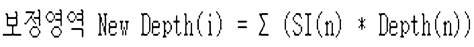
Equation 1
여기서, i는 보정영역의 좌/우측까지의 pixel index, n은 interpolation 구간으로 보정영역보다 통상적으로는 약간 작게 설정한다. 상기 SI(n) 는 입력영상(필터링된 영상)의 화소값, Depth(n)은 깊이맵의 화소값, New Depth(i)는 화소 위치 i에서의 보정된 깊이값을 의미한다.Here, i is a pixel index to the left / right side of the correction region, and n is an interpolation section, which is usually set slightly smaller than the correction region. SI (n) denotes a pixel value of an input image (filtered image), Depth (n) denotes a pixel value of a depth map, and New Depth (i) denotes a corrected depth value at pixel position i.
다시 말하면, 상기 깊이 값 보정부(230)는 상기 필터링된 영상의 경계특성이 깊이 맵의 경계특성과 일치한다는 전제조건에 따라, 상기 보정 영역에 대해서 필터링된 영상과 깊이맵의 보간을 수학식 1에 따라 수행한다. 상기 interpolation은 원영상의 경계특성이 깊이맵에 반영되어 좀더 경계특성이 확연히 구별되는 깊이맵으로 보정된다.In other words, the depth value corrector 230 performs interpolation of the filtered image and the depth map on the correction region according to the precondition that the boundary characteristics of the filtered image match the boundary characteristics of the depth map. Perform according to. The interpolation is corrected to a depth map in which the boundary characteristics of the original image are reflected in the depth map and the boundary characteristics are more clearly distinguished.
상기 수학식 1을 통해 보정 영역의 깊이 값이 정해지면, 상기 깊이 값 보정부(230)는 상기 외곽영역에 대한 깊이값들을 보정한다.When the depth value of the correction region is determined through Equation 1, the depth value correction unit 230 corrects the depth values of the outer region.
상기 외곽영역의 보정은 경계면에 해당하는 보정영역과는 다르게 깊이 맵의 변화도가 매우 작은 안정된 영역으로, 이미 입체를 표현하기 위한 객체의 영역에 포함되어있기 때문에, 통상적으로는 보정을 하지 않거나 또는 깊이맵의 안정성을 위해서 가우시안 필티링 또는 이와 유사한 효과를 내는 저역통과 필터링을 수행한다. 상기 외곽영역을 위한 필터링은 전체적인 깊이맵의 안정성을 위해서 부가적으로 수행한다.Unlike the correction region corresponding to the boundary surface, the correction of the outer region is a stable region with a very small degree of change in the depth map. For the stability of the depth map, Gaussian filleting or similar lowpass filtering is performed. The filtering for the outer region is additionally performed for the stability of the overall depth map.
상기와 같이 외곽영역에 대한 깊이값들이 보정되면, 상기 깊이 값 보정부(230)는 상기 인근영역에 대한 깊이 값 보정을 수행한다. 즉, 상기 인근영역은 보정영역과 외곽영역의 중간영역으로 각 영역이 서로 다르게 보정이 이루어졌기 때문에 이 영역에 대한 연결을 위한 완충영역이다. When the depth values for the outer region are corrected as described above, the depth value corrector 230 performs the depth value correction for the neighboring region. In other words, the neighboring area is an intermediate area between the correction area and the outer area, and is a buffer area for connection to this area because each area is corrected differently.
따라서, 상기 깊이 값 보정부(230)는 수학식 2를 이용하여 인근영역에 대한 깊이값 보정을 수행한다. Therefore, the depth value correcting unit 230 performs depth value correction on the neighboring area by using Equation 2.
수학식 2 
Equation 2
여기서, i는 보정영역의 한쪽면에서 외곽영역의 한쪽면까지의 화소 index로 인근영역의 화소 위치를 말하고, A는 보정영역에서 인근영역에 접한 화소값을 말한다.Here, i is a pixel index from one side of the correction region to one side of the outer region, and refers to the pixel position of the neighboring region, and A is a pixel value in contact with the neighboring region in the correction region.
상기 delta는 수학식 3과 같이 정의된다. The delta is defined as in Equation 3.
수학식 3 
Equation 3
여기서, A는 보정영역에서 인근영역에 접한 화소값, B는 외곽영역에서 인근영역에 접한 화소값, j는 A값을 가지는 화소의 위치 index, k는 B의 화소값을 가지는 화소의 위치 index이다.Where A is a pixel value in contact with a neighboring region in the correction region, B is a pixel value in contact with a neighboring region in the outer region, j is a position index of a pixel having a value A, and k is a position index of a pixel having a pixel value of B. .
결과적으로 delta란 보정영역과 외곽영역을 연결하기 위한 화소의 변화도에 해당하는 기울기 값이다. 따라서 수학식 2에 따른 인근영역의 깊이 값은 보정영역의 마지막 화소값에서 외곽영역의 시작위치에 해당하는 화소값을 선형적으로 연결하여 깊이맵의 연속성을 보장하기 위한 것이다. As a result, delta is a slope value corresponding to the degree of change of the pixel for connecting the correction region and the outer region. Therefore, the depth value of the neighboring region according to Equation 2 is to guarantee the continuity of the depth map by linearly connecting the pixel value corresponding to the start position of the outer region from the last pixel value of the correction region.
상기와 같은 방법을 이용하여 상기 깊이 값 보정부(230)는 각 영역에 해당하는 깊이값들이 보정된 깊이맵을 생성하게 된다.Using the above method, the depth value correcting unit 230 generates a depth map in which depth values corresponding to each region are corrected.
도 3은 본 발명에 따른 입체 영상 변환 장치가 2차원의 입력 영상을 3차원의 입체 영상으로 변환하는 방법을 나타낸 흐름도, 도 4는 본 발명에 따른 보정 전후의 깊이 맵을 설명하기 위한 예시도이다. 3 is a flowchart illustrating a method of converting a 2D input image into a 3D stereoscopic image by the stereoscopic image converting apparatus according to the present invention, and FIG. 4 is an exemplary diagram for describing a depth map before and after correction according to the present invention. .
도 3을 참조하면, 입체 영상 변환 장치는 2차원의 입력 영상을 분석하여 적어도 하나의 특성 정보를 추출한다(S302). 여기서, 상기 특성정보는 경계(edge) 정보, 컬러(color) 정보, 휘도(luminance) 정보, 모션(motion) 정보, 히스토그램(histogram) 정보 등을 포함한다.Referring to FIG. 3, the 3D image conversion apparatus analyzes a two-dimensional input image to extract at least one characteristic information (S302). Here, the characteristic information includes edge information, color information, luminance information, motion information, histogram information, and the like.
상기 S302의 수행 후, 상기 입체 영상 변환 장치는 상기 특성 정보를 기초로 상기 입력 영상에 대한 깊이 맵을 생성한다(S304).After performing the step S302, the stereoscopic image conversion apparatus generates a depth map of the input image based on the characteristic information (S304).
그런 다음 상기 입체 영상 변환 장치는 상기 입력 영상을 필터링하고, 그 필터링된 영상을 이용하여 상기 생성된 깊이맵을 보정한다(S306). 상기 입체 영상 변환 장치가 깊이맵을 보정하는 방법에 대한 상세한 설명은 도 5를 참조하기로 한다.Then, the stereoscopic image converting device filters the input image and corrects the generated depth map using the filtered image (S306). The method of correcting the depth map by the stereoscopic image conversion apparatus will be described with reference to FIG. 5.
상기 S304에서 생성된 깊이맵과 상기 S306에서 보정된 깊이맵을 비교하기 위해 도 4를 참조하기로 한다. Reference will be made to FIG. 4 to compare the depth map generated in S304 with the depth map corrected in S306.
도 4의 (a)는 입체변환을 위한 원영상(입력영상임)의 예이다. (a)와 같은 원 영상(400)을 이용하여 깊이맵을 생성하면 도 4의 (b)와 같은 깊이 맵(410)이 생성된다. 즉, 상기 원영상(400)의 경계 특성을 기초로 깊이맵을 생성하면, 도 4의 (b)와 같은 깊이 맵(410)이 생성된다. 4A is an example of an original image (which is an input image) for stereoscopic conversion. When the depth map is generated using the original image 400 as shown in (a), the depth map 410 as shown in FIG. 4 (b) is generated. That is, when the depth map is generated based on the boundary characteristic of the original image 400, the depth map 410 as shown in FIG. 4B is generated.
상기 생성된 깊이 맵(410)을 원영상(400)과 비교하여 보면, 전체적인 깊이맵(410)의 특성은 원영상(400)의 깊이 값을 적절하게 표현하고 있지만, 객체간의 경계면을 살펴보면 깊이 맵(410)이 매우 거칠게 표현되어 있다. 예를 들면, A사람과 B사람의 경계면에 대해 원영상(400)과 깊이맵(410)을 비교해 보면, 깊이맵(410)에서는 A사람과 B사람의 경계가 명확하지 않고, 시각적으로 자연스럽게 일치하지 않는 부분적인 오류가 존재한다. 즉, 깊이 맵(410)은 많은 굴곡을 가지는 형태로 표현이 되어, 원 영상(400)에 비해 해상도가 매우 낮은 특성을 가지고 있다.Comparing the generated depth map 410 with the original image 400, the characteristics of the overall depth map 410 properly represents the depth value of the original image 400, but when looking at the interface between the objects, the depth map 410 is very roughly expressed. For example, if the original image 400 and the depth map 410 are compared with respect to the boundary between person A and person B, in the depth map 410, the boundary between person A and person B is not clear and visually matches naturally. There is a partial error that does not. That is, the depth map 410 is represented in a form having a lot of curvature, and has a very low resolution compared to the original image 400.
(b)와 같이 원영상(400)에 비해서 경계면에 부분적인 오류가 존재하고 해상도가 낮은 특성을 가지는 깊이맵(410)에 대해서, 원영상(400)을 이용하여 자연스러운 입체감을 표현하기 위해 경계면을 보정함과 동시에 원 영상(400)의 해상도와 같은 수준의 깊이맵으로 보정하면 도 4의 (c)와 같이 경계면이 보정된 깊이 맵(420)이 생성된다.As shown in (b), in the depth map 410 having a partial error at the boundary surface compared to the original image 400 and having a low resolution, the boundary surface is used to express a natural three-dimensional effect using the original image 400. At the same time as the correction of the depth map at the same level as the resolution of the original image 400, the depth map 420 with the boundary surface corrected is generated as shown in FIG.
즉, 상기 원영상(400)을 필터링하고, 그 필터링된 영상에서 화소의 특성 변화도가 가장 큰 경계면인 A사람과 B사람간의 경계면에 해당하는 깊이값을 수학식 1을 이용하여 보정하고, 인근영역 및 외곽영역의 깊이값을 보정하면, 도 4의 (c )와 같은 보정된 깊이맵(420)이 생성된다. 상기 인근영역 및 외곽영역의 깊이값을 보정하는 방법에 대한 상세한 설명은 도 2를 참조하기로 한다.That is, the original image 400 is filtered, and the depth value corresponding to the interface between person A and person B, which is the boundary with the greatest degree of characteristic change of pixels in the filtered image, is corrected using Equation 1, When the depth values of the region and the outer region are corrected, the corrected depth map 420 as shown in FIG. 4C is generated. A detailed description of a method of correcting depth values of the neighboring area and the outer area will be given with reference to FIG. 2.
상기 보정된 깊이맵(420)을 살펴보면, A사람과 B사람간의 경계가 명확하여 A사람과 B사람을 명확하게 구분할 수 있고, 원 영상(400)과 비슷한 해상도를 가지고 있다는 것을 알 수 있다. Looking at the corrected depth map 420, it can be seen that the boundary between person A and person B is clear so that person A and person B can be clearly distinguished and have a resolution similar to that of the original image 400.
다시 도 3을 참조하면, 상기 S306의 수행 후, 상기 입체 영상 변환 장치는 상기 보정된 깊이 맵을 이용하여 상기 입력 영상을 3차원의 입체 영상으로 변환한다(S308).Referring to FIG. 3 again, after performing the S306, the stereoscopic image converting apparatus converts the input image into a 3D stereoscopic image using the corrected depth map (S308).
상기와 같이 원영상과 일치하지 않는 깊이맵의 경계 특성을 원영상을 고려하여 최대한 일치하도록 보정하고, 그 보정된 깊이맵을 이용하여 2차원의 영상을 3차원의 입체 영상으로 변환하면, 불일치로 인한 어지러움을 완화시킬 수 있다.As described above, the boundary characteristics of the depth map that do not match the original image are corrected as much as possible in consideration of the original image, and the 2D image is converted into a 3D stereoscopic image using the corrected depth map. It can alleviate dizziness caused.
도 5는 본 발명에 따른 깊이 맵 보정 장치가 깊이 맵을 보정하는 방법을 나타낸 흐름도, 도 6은 본 발명에 따른 깊이 맵의 보정 과정을 설명하기 위한 도면이다. 5 is a flowchart illustrating a method of correcting a depth map by a depth map correcting apparatus according to the present invention, and FIG. 6 is a view for explaining a process of correcting a depth map according to the present invention.
도 5를 참조하면, 깊이 맵 보정 장치는 2차원의 입력 영상(이하에서는 원영상이라 칭하기로 함)에 대해 노이즈 필터링 및 sharp 특성 개선 필터링을 수행한다(S502). 즉, 영상의 경계면은 노이즈와 같은 외부의 영향을 많이 받기 때문에, 원영상은 최대한 노이즈가 없을수록 보정 효과를 높일 수 있다. 따라서, 깊이 맵 보정 장치는 영상처리를 하기 전에 노이즈와 같은 영향을 최소화하기 위해 노이즈 필터링을 수행하고, 경계면의 특성을 강화시키기 위해 Sharp 특성 개선 필터링을 수행한다. 상기 Sharp 특성 개선 필터링에 대해 도 4의 (a)를 참조하면, 영상내의 사람과 산과의 구별 경계면, 산과 하늘 사이의 구별 경계면 등이 각 객체의 구별 경계선이면서 입체의 경계면이기 때문에 이런 경계면을 시각적으로 좀더 구별되도록 경계면 사이 화소값의 편차를 크게 만드는 것이 Sharp 특성 개선 필터링일 수 있다. Referring to FIG. 5, the depth map correction apparatus performs noise filtering and sharp characteristic enhancement filtering on a two-dimensional input image (hereinafter referred to as an original image) (S502). That is, since the boundary of the image is greatly influenced by external influences such as noise, the original image can enhance the correction effect as much as there is no noise. Therefore, the depth map correction apparatus performs noise filtering to minimize effects such as noise before performing image processing, and performs sharp characteristic enhancement filtering to enhance the characteristics of the boundary surface. Referring to (a) of FIG. 4 for the sharp characteristic improvement filtering, the boundary between the human and the mountain in the image, the boundary between the mountain and the sky, and the like are the distinct boundary and the three-dimensional boundary of each object. The sharp characteristic enhancement filtering may be to make the deviation of the pixel value between the interfaces more distinctive.
상기 S502의 수행 후, 상기 깊이 맵 보정 장치는 상기 필터링된 영상에서 화소의 특성 변화도가 큰 경계면을 선택하고(S504), 상기 경계면을 기준으로 보정 정도에 따라 보정영역, 인근영역, 외곽영역으로 구분한다(S506).After performing S502, the depth map correction apparatus selects a boundary surface having a large degree of characteristic change of pixels in the filtered image (S504), and moves to a correction region, a neighboring region, and an outer region according to the degree of correction based on the boundary surface. (S506).
상기 보정영역은 상기 필터링된 영상의 경계면에 해당하는 영역으로 위치 변화에 따라 화소의 특성 또는 크기의 변화도가 큰 영역으로 선택되며, 각 경계면을 기준으로 깊이 맵 보정을 수행하기 위한 영역이다. 상기 인근영역은 상기 보정 영역의 인접영역으로, 상기 보정영역의 깊이값 보정 후 좌/우 영역에 대한 깊이 값의 설정을 위한 영역을 말한다. 상기 외곽영역은 상기 보정영역과 인근영역을 제외한 영역으로, 각 경계면 외곽영역으로 전체적인 깊이 값 보정을 위한 영역을 말한다. The correction area is an area corresponding to the boundary of the filtered image and is selected as a region having a large change in characteristic or size of a pixel according to a position change, and is a region for performing depth map correction based on each boundary. The neighboring area is an area adjacent to the correction area and refers to an area for setting depth values for left and right areas after depth value correction of the correction area. The outer region is a region except for the correction region and the neighboring region, and refers to the region for the overall depth value correction as the outer region of each boundary surface.
상기와 같이 구분된 각각의 영역은 보정의 정도에 따라서 먼저 보정영역의 보정범위가 설정되고, 보정범위를 벗어난 좀더 안정된 깊이값을 가지는 인근영역을 설정한 후, 그 외의 영역을 외곽 영역으로 정의한다. Each area divided as described above is first set a correction range of the correction region according to the degree of correction, and set a neighboring region having a more stable depth value out of the correction range, and then define the other region as the outer region. .
상기 S506의 수행 후, 상기 깊이 맵 보정 장치는 상기 보정영역에 대해서 상기 필터링된 영상과 기 생성된 깊이맵간의 보간(Interpolation)을 수행하여 상기 보정영역의 깊이값을 보정한다(S508).After the operation S506 is performed, the depth map correction device corrects the depth value of the correction area by performing interpolation between the filtered image and the previously generated depth map with respect to the correction area (S508).
즉, 상기 깊이 맵 보정 장치는 수학식 1을 이용하여 보정 영역에 해당하는 깊이 맵의 깊이 값을 보정한다. That is, the depth map correction apparatus corrects the depth value of the depth map corresponding to the correction region by using Equation 1.
다시 말하면, 상기 깊이 맵 보정 장치는 필터링된 영상의 경계특성이 깊이 맵의 경계특성과 일치한다는 전제조건에 따라, 상기 보정 영역에 대해서 필터링된 영상과 깊이맵의 보간을 수학식 1에 따라 수행한다. 상기 보간(interpolation)은 원영상의 경계특성이 깊이맵에 반영되어 좀더 경계특성이 확연히 구별되는 깊이맵으로 보정된다.In other words, the depth map correction apparatus performs interpolation of the filtered image and the depth map with respect to the correction region according to the precondition that the boundary characteristics of the filtered image match the boundary characteristics of the depth map, according to Equation 1. . The interpolation is corrected to a depth map in which the boundary characteristics of the original image are reflected in the depth map and the boundary characteristics are more clearly distinguished.
상기 S508에 의해 보정 영역에 해당하는 깊이 맵의 깊이값들이 보정되면, 상기 깊이 맵 보정 장치는 상기 외곽영역에 대한 깊이값들을 보정한다(S510).When the depth values of the depth map corresponding to the correction region are corrected by S508, the depth map correction apparatus corrects the depth values of the outer region (S510).
상기 외곽영역의 보정은 경계면에 해당하는 보정영역과는 다르게 깊이 맵의 변화도가 매우 작은 안정된 영역으로 이미 입체를 표현하기 위한 객체의 영역에 포함되어있기 때문에 통상적으로는 보정을 하지 않거나 또는 깊이맵의 안정성을 위해서 가우시안 필티링 또는 이와 유사한 효과를 내는 저역통과 필터링을 수행한다. 상기 외곽영역을 위한 필터링은 전체적인 깊이맵의 안정성을 위해서 부가적으로 수행한다.Unlike the correction area corresponding to the boundary surface, the correction of the outer area is a stable area having a very small degree of change in the depth map. Since the correction of the outer area is already included in the area of the object for representing a stereoscopic image, the correction is usually not performed or the depth map is not. To ensure the stability of the Gaussian filleting or similar low-pass filtering is performed. The filtering for the outer region is additionally performed for the stability of the overall depth map.
상기 S510이 수행되면, 상기 깊이 맵 보정 장치는 인근영역에 대한 깊이값 보정을 수행한다(S512). 즉, 상기 인근영역의 깊이값 보정은 상기 보정영역과 외곽영역의 중간영역으로 각 영역이 서로 다르게 보정이 이루어졌기 때문에 이 영역에 대한 연결을 위한 완충영역이다. 따라서, 상기 깊이 맵 보정 장치는 수학식 2를 이용하여 인근영역에 대한 깊이값 보정을 수행한다. When the S510 is performed, the depth map correcting apparatus performs depth value correction on the neighboring region (S512). That is, the depth value correction of the neighboring region is a buffer region for connection to this region because each region has been differently corrected to the middle region of the correction region and the outer region. Therefore, the depth map correcting apparatus performs depth value correction on the neighboring region by using Equation 2.
상기 S512가 수행되면, 상기 깊이맵 보정 장치는 각 영역에 해당하는 깊이값들이 보정된 깊이맵을 생성하게 된다(S514).When the S512 is performed, the depth map correcting apparatus generates a depth map in which depth values corresponding to each region are corrected (S514).
상기 깊이 맵 보정 장치가 원 영상을 이용하여 깊이 맵을 보정하는 방법에 대해 도 6을 참조하여 설명하기로 한다. A method of correcting the depth map using the original image by the depth map correcting apparatus will be described with reference to FIG. 6.
상기 깊이 맵 보정 장치가 깊이 맵을 보정하기 위한 영상은 x, y 공간의 2차원의 영상이지만, 설명의 편의를 위해 수평방향의 축을 기점으로 1차원적으로 표현하여 설명하기로 한다. The image for correcting the depth map by the depth map correction apparatus is a two-dimensional image in x and y spaces, but for convenience of description, the image will be described by expressing one-dimensionally from the horizontal axis as a starting point.
도 6을 참조하면, (1)은 원영상의 위치 변화에 따른 화소의 특성(또는 크기, 값 등임)을 나타낸 것으로, (1)과 같은 원 영상에 대해 노이즈 및 샤프 특성 필터링을 수행하면 (2)와 같은 화소의 특성을 갖는 영상으로 변환된다. 즉, 원영상에 노이즈 및 샤프 특성 필터링을 수행하면, (2)와 같이 영상의 노이즈 성분이 제거되고 경계면의 구별이 명확하게 된다. Referring to FIG. 6, (1) shows the characteristics (or sizes, values, etc.) of pixels according to the positional change of the original image. When noise and sharp characteristic filtering is performed on the original image as shown in (1), (2) Is converted into an image having a characteristic of a pixel such as That is, when noise and sharp characteristic filtering are performed on the original image, noise components of the image are removed as shown in (2), and distinction of the boundary surface becomes clear.
(2)에서 변화도가 큰 경계면을 선택하면, 상승부분과 하강부분의 V1과 V2가 선정된다. 상기 선정된 V1, V2의 경계면을 기준으로 보정 정도에 따라 보정영역(a), 인근영역(b), 외곽영역(c)으로 구분한다. 각각의 영역은 보정 정도에 따라 먼저 보정영역(a)의 보정범위가 설정되고 보정범위를 벗어난 좀더 안정된 깊이값을 가지는 인근영역(b)를 설정한다. 그리고 그 외의 영역을 외곽영역(c)으로 설정한다. In (2), if the interface with a large degree of change is selected, V1 and V2 of the rising part and the falling part are selected. On the basis of the boundary of the selected V1, V2 based on the degree of correction is divided into a correction region (a), a neighboring region (b), the outer region (c). Each region first sets a correction region of the correction region a according to the degree of correction, and sets a neighboring region b having a more stable depth value out of the correction range. The other area is set as the outer area (c).
상기 보정영역(a)은 필터링된 영상의 경계면에 해당하는 영역으로 위치 변화에 따라 화소값의 변화가 큰 영역이 선택되고, 인근영역(b)은 보정 영역(a)의 인접영역으로 보정영역(a)과 일정 거리에 있는 영역이 선택되고, 외곽 영역(c)은 보정영역(a)과 인근영역(b)을 제외한 영역이 선택된다. The correction area (a) is an area corresponding to the boundary of the filtered image, and an area having a large change in pixel value is selected according to a change in position, and the neighboring area (b) is an adjacent area of the correction area (a). A region at a certain distance from a) is selected, and an outer region c is selected except for the correction region a and the neighboring region b.
상기 깊이 맵 보정 장치는 필터링된 영상의 경계 특성이 깊이 맵의 경계 특성과 일치한다는 전제조건에 따라, 보정영역(a)에 대해서 필터링된 영상(2)와 깊이 맵(3)의 보간을 수행한다. 여기서, 상기 깊이 맵(3)은 상기 원영상(1)으로부터 추출된 특성 정보를 이용하여 생성된 깊이 맵이다. The depth map correction apparatus performs interpolation of the filtered image 2 and the depth map 3 on the correction region a according to the precondition that the boundary characteristics of the filtered image match the boundary characteristics of the depth map. . Here, the depth map 3 is a depth map generated using the characteristic information extracted from the original image 1.
그런 다음 상기 깊이 맵 보정 장치는 인근영역과 외곽영역에 대해서도 보정을 수행하여 (4)와 같이 보정된 깊이 맵을 얻게 된다. Then, the depth map corrector performs correction on the neighboring area and the outer area to obtain the corrected depth map as shown in (4).
상기 보정영역, 인근영역, 외곽영역에 대한 깊이값을 보정하는 방법에 대한 상세한 설명은 도 2를 참조하기로 한다. A detailed description of a method of correcting depth values for the correction region, the neighboring region, and the outer region will be given with reference to FIG. 2.
상기와 같은 과정을 통해 보정된 깊이맵(4)을 기 생성된 깊이맵(3)과 비교하면, 보정된 깊이맵(4)에서 보정영역(a)의 깊이 값이 기 생성된 깊이맵(3)의 해당 영역의 깊이 값보다 원영상(1)과 일치됨을 알 수 있다. When the depth map 4 corrected through the above process is compared with the previously generated depth map 3, the depth map 3 of which the depth value of the correction region a is previously generated is corrected in the corrected depth map 4. It can be seen that the original image 1 coincides with the depth value of the corresponding area of the.
또한, 보정후의 경계값을 살펴보면 경계면은 원영상에 최대한 가깝게 이동하는 형태로 보정이 이루어지며 깊이맵의 변동성을 최대한 억제된 형태로 표현이 된다. 물론 깊이맵 원래의 부분적인 변동 부분이 보정 영역내에서 완전히 제거될 수는 없지만 사람의 시각적인 특성은 경계의 일치 여부에 더욱 민감하기 때문에 실제 입체감은 많은 개선을 이룰 수 있다.In addition, when looking at the boundary value after the correction, the boundary surface is corrected to move as close as possible to the original image, and the variability of the depth map is expressed in the most suppressed form. Of course, the partial fluctuations of the original depth map cannot be completely removed within the correction region, but since the visual characteristics of the person are more sensitive to the boundary agreement, the actual three-dimensional effect can make a lot of improvements.
본 발명에 따른 입체 영상 변환 장치 또는 깊이 맵 보정 장치는 개인용 컴퓨터, 태블릿 PC, 노트북, 휴대폰, 스마트폰 등의 형태로도 구현 가능하고, 본 발명에 따른 입체 영상 변환 방법 또는 깊이 맵 보정 방법은 이들 장치에 구비된 하나 혹은 그 이상의 코어로 이루어진 프로세서에 의하여 실행 가능할 수 있다.The stereoscopic image conversion device or the depth map correction device according to the present invention can be implemented in the form of a personal computer, a tablet PC, a notebook computer, a mobile phone, a smartphone, and the like. It may be executable by a processor consisting of one or more cores included in the device.
본 발명의 또 다른 측면에 따르면, 2차원의 입력 영상에 대해 노이즈 필터링 또는 샤프(sharp) 특성 개선 필터링을 수행하는 단계, 상기 필터링된 영상에서 화소의 특성 변화도가 가장 큰 경계면을 선택하고, 상기 경계면을 기준으로 보정 정도에 따라 보정영역, 인근영역, 외곽영역으로 구분하는 단계, 상기 보정영역에 대해서 필터링된 영상과 깊이맵의 보간을 수행하여 깊이값을 보정하고, 상기 외곽영역 및 상기 인근영역의 깊이값 보정을 통해 보정된 깊이맵을 생성하는 단계를 포함하는 깊이 맵 보정 방법이 프로그램으로 기록되고 전자 장치에서 판독 가능한 기록매체가 제공된다. According to another aspect of the present invention, performing noise filtering or sharp characteristic enhancement filtering on a two-dimensional input image, selecting an interface having the largest characteristic variation of a pixel in the filtered image, Dividing the image into a correction region, a neighboring region, and an outer region according to the degree of correction based on the boundary surface, and correcting the depth value by performing interpolation of the filtered image and the depth map with respect to the correction region, and the outer region and the neighboring region. A depth map correction method comprising generating a corrected depth map by correcting a depth value of is provided by a program, and a recording medium readable by the electronic device is provided.
본 발명의 또 다른 측면에 따르면, 2차원의 입력영상을 분석하여 적어도 하나의 특성 정보를 추출하는 단계, 상기 특성 정보를 기초로 상기 입력 영상에 대한 깊이 맵을 생성하는 단계, 상기 입력 영상을 필터링하고, 그 필터링된 입력영상을 이용하여 상기 생성된 깊이맵을 보정하는 단계, 상기 보정된 깊이맵을 이용하여 상기 입력 영상을 3차원의 입체영상으로 변환하는 단계를 포함하는 입체 영상 변환 방법이 프로그램으로 기록되고 전자 장치에서 판독 가능한 기록매체가 제공된다. According to another aspect of the invention, the step of extracting at least one characteristic information by analyzing a two-dimensional input image, generating a depth map for the input image based on the characteristic information, filtering the input image And correcting the generated depth map by using the filtered input image, and converting the input image into a three-dimensional stereoscopic image using the corrected depth map. There is provided a recording medium recorded in the form and readable by the electronic device.
깊이 맵 보정 방법 및 입체 영상 변환 방법은 프로그램으로 작성 가능하며, 프로그램을 구성하는 코드들 및 코드 세그먼트들은 당해 분야의 프로그래머에 의하여 용이하게 추론될 수 있다. The depth map correction method and the stereoscopic image conversion method can be written in a program, and codes and code segments constituting the program can be easily inferred by a programmer in the art.
본 발명에 따라 깊이 맵 보정 장치 및 이를 이용한 입체 영상 변환 장치는 프로세서, 메모리, 저장 장치 및 입/출력 장치를 컴포넌트로서 포함할 수 있으며, 이들 컴포넌트는 예컨대 시스템 버스를 이용하여 상호 접속될 수 있다. According to the present invention, a depth map correction device and a stereoscopic image conversion device using the same may include a processor, a memory, a storage device, and an input / output device as components, and these components may be interconnected using, for example, a system bus.
상기 프로세서는 본 장치 내에서의 실행을 위한 명령을 처리할 수 있다. 일 구현예에서, 이 프로세서는 싱글 쓰레드(Single-threaded) 프로세서일 수 있으며, 다른 구현예에서 본 프로세서는 멀티 쓰레드(Multi0threaded) 프로세서일 수 있다.본 프로세서는 메모리 또는 저장 장치 상에 저장된 명령을 처리하는 것이 가능한다. The processor may process instructions for execution within the device. In one implementation, the processor may be a single-threaded processor, and in other implementations, the processor may be a multi-threaded processor. The processor processes instructions stored on memory or storage devices. It is possible to do
한편, 메모리는 본 장치 내에서 정보를 저장한다. 일 구현예의 경우, 메모리는 컴퓨터로 판독 가능한 매체이다. 일 구현예에서, 메모리는 휘발성 메모리 유닛일 수 있으며, 다른 구현예의 경우, 메모리는 비휘발성 메모리 유닛일 수도 있다. 상술한 저장 장치는 본 장치에 대한 대용량 저장부를 제공할 수 있다. 일 구현예의 경우, 저장 장치는 컴퓨터로 판독 가능한 매체이다. 다양한 서로 다른 구현예에서, 저장 장치는 예컨대 하드디스크 장치, 광학디스크장치, 혹은 어떤 다른 대용량 저장 장치를 포함할 수도 있다. On the other hand, the memory stores information in the apparatus. In one embodiment, the memory is a computer readable medium. In one implementation, the memory may be a volatile memory unit, and for other implementations, the memory may be a nonvolatile memory unit. The storage device described above can provide a mass storage for the device. In one embodiment, the storage device is a computer readable medium. In various different implementations, the storage device may include, for example, a hard disk device, an optical disk device, or some other mass storage device.
상술한 입/출력 장치는 본 발명에 따른 장치에 대한 입/출력 동작을 제공한다. 일 구현예에서, 입/출력 장치는 예컨대 이더넷 카드와 같은 하나 이상의 네트워크 인터페이스 장치, 예컨대 RS-232 포트와 같은 직렬 통신 장치 및/또는 예컨대 802.11 카드와 같은 무선 인터페이스 장치를 포함할 수 있다. 다른 구현예에서, 입/출력 장치는 다른 입/출력 장치로 출력 데이터를 전송하고 입력 데이터를 수신하도록 구성된 드라이버 장치, 예컨대 키보드, 프린터 및 디스플레이 장치를 포함할 수 있다. The above-described input / output device provides an input / output operation for the device according to the present invention. In one implementation, the input / output device may include one or more network interface devices such as, for example, an Ethernet card, such as a serial communication device such as an RS-232 port and / or a wireless interface device such as, for example, an 802.11 card. In other implementations, the input / output device can include driver devices, such as keyboards, printers, and display devices, configured to send output data to and receive input data from other input / output devices.
본 발명에 따른 장치는 하나 이상의 프로세서로 하여금 앞서 설명한 기능들과 프로세스를 수행하도록 하는 명령에 의하여 구동될 수 있다. 예를 들어 그러한 명령으로는, 예컨대 JavaScript나 ECMAScript 명령 등의 스크립트 명령과 같이 해석되는 명령이나 실행 가능한 코드 혹은 컴퓨터로 판독 가능한 매체에 저장되는 기타의 명령이 포함될 수 있다. 나아가 본 발명에 따른 장치는 서버 팜(Sever Farm)과 같이 네트워크에 걸쳐서 분산형으로 구현될 수 있으며, 혹은 단일의 컴퓨터 장치에서 구현될 수도 있다. The apparatus according to the invention may be driven by instructions that cause one or more processors to perform the functions and processes described above. For example, such instructions may include instructions that are interpreted, for example, script instructions such as JavaScript or ECMAScript instructions, or executable code or other instructions stored on a computer readable medium. Furthermore, the device according to the present invention may be implemented in a distributed manner over a network, such as a server farm, or may be implemented in a single computer device.
비록 본 명세서와 도면에서는 예시적인 장치 구성을 기술하고 있지만, 본 명세서에서 설명하는 기능적인 동작과 주제의 구현물들은 다른 유형의 디지털 전자 회로로 구현되거나, 본 명세서에서 개시하는 구조 및 그 구조적인 등가물들을 포함하는 컴퓨터 소프트웨어, 펌웨어 혹은 하드웨어로 구현되거나, 이들 중 하나 이상의 결합으로 구현 가능하다. 본 명세서에서 설명하는 주제의 구현물들은 하나 이상의 컴퓨터 프로그램 제품, 다시 말해 본 발명에 따른 장치의 동작을 제어하기 위하여 혹은 이것에 의한 실행을 위하여 유형의 프로그램 저장매체 상에 인코딩된 컴퓨터 프로그램 명령에 관한 하나 이상의 모듈로서 구현될 수 있다. 컴퓨터로 판독 가능한 매체는 기계로 판독 가능한 저장 장치, 기계로 판독 가능한 저장 기판, 메모리 장치, 기계로 판독 가능한 전파형 신호에 영향을 미치는 물질의 조성물 혹은 이들 중 하나 이상의 조합일 수 있다.Although the specification and drawings describe exemplary device configurations, the functional operations and subject matter implementations described herein may be embodied in other types of digital electronic circuitry, or modified from the structures and structural equivalents disclosed herein. It may be implemented in computer software, firmware or hardware, including, or a combination of one or more of them. Implementations of the subject matter described herein relate to one or more computer program products, ie computer program instructions encoded on a program storage medium of tangible type for controlling or by the operation of an apparatus according to the invention. It may be implemented as the above module. The computer readable medium may be a machine readable storage device, a machine readable storage substrate, a memory device, a composition of materials affecting a machine readable propagated signal, or a combination of one or more thereof.
"처리 시스템", "처리 장치" 및 "하위 시스템"이라는 용어는 예컨대 프로그래머블 프로세서, 컴퓨터 혹은 다중 프로세서나 컴퓨터를 포함하여 데이터를 처리하기 위한 모든 기구, 장치 및 기계를 포괄한다. 처리 시스템은, 하드웨어에 부가하여, 예컨대 프로세서 펌웨어를 구성하는 코드, 프로토콜 스택, 데이터베이스 관리 시스템, 운영 체제 혹은 이들 중 하나 이상의 조합 등 요청 시 컴퓨터 프로그램에 대한 실행 환경을 형성하는 코드를 포함할 수 있다. The terms "processing system", "processing device" and "subsystem" encompass all the instruments, devices and machines for processing data, including, for example, programmable processors, computers or multiple processors or computers. The processing system may include, in addition to hardware, code that forms an execution environment for a computer program on demand, such as code constituting processor firmware, a protocol stack, a database management system, an operating system, or a combination of one or more thereof. .
본 발명에 따른 장치에 탑재되고 본 발명에 따른 방법을 실행하는 컴퓨터 프로그램(프로그램, 소프트웨어, 소프트웨어 어플리케이션, 스크립트 혹은 코드로도 알려져 있음)은 컴파일되거나 해석된 언어나 선험적 혹은 절차적 언어를 포함하는 프로그래밍 언어의 어떠한 형태로도 작성될 수 있으며, 독립형 프로그램이나 모듈, 컴포넌트, 서브루틴 혹은 컴퓨터 환경에서 사용하기에 적합한 다른 유닛을 포함하여 어떠한 형태로도 전개될 수 있다. 컴퓨터 프로그램이 파일 시스템의 파일에 반드시 대응해야 하는 것은 아니다. 프로그램은 요청된 프로그램에 제공되는 단일 파일 내에, 혹은 다중의 상호 작용하는 파일(예컨대, 하나 이상의 모듈, 하위 프로그램 혹은 코드의 일부를 저장하는 파일) 내에, 혹은 다른 프로그램이나 데이터를 보유하는 파일의 일부(예컨대, 마크업 언어 문서 내에 저장되는 하나 이상의 스크립트) 내에 저장될 수 있다. 컴퓨터 프로그램은 하나의 사이트에 위치하거나 복수의 사이트에 걸쳐서 분산되어 통신 네트워크에 의해 상호 접속된 다중 컴퓨터나 하나의 컴퓨터 상에서 실행되도록 전개될 수 있다. A computer program (also known as a program, software, software application, script or code) mounted on an apparatus according to the invention and executing a method according to the invention is a programming comprising a compiled or interpreted language or a priori or procedural language. It can be written in any form of language, and can be deployed in any form, including stand-alone programs or modules, components, subroutines, or other units suitable for use in a computer environment. A computer program does not necessarily correspond to a file in a file system. A program may be in a single file provided to the requested program, in multiple interactive files (eg, a file that stores one or more modules, subprograms, or parts of code), or part of a file that holds other programs or data. (Eg, one or more scripts stored in a markup language document). The computer program may be deployed to run on a single computer or on multiple computers located at one site or distributed across multiple sites and interconnected by a communication network.
컴퓨터 프로그램 명령어와 데이터를 저장하기에 적합한 컴퓨터로 판독 가능한 매체는, 예컨대 EPROM, EEPROM 및 플래시메모리 장치와 같은 반도체 메모리 장치, 예컨대 내부 하드디스크나 외장형 디스크와 같은 자기 디스크, 자기광학 디스크 및 CD-ROM과 DVD-ROM 디스크를 포함하여 모든 형태의 비휘발성 메모리, 매체 및 메모리 장치를 포함한다. 프로세서와 메모리는 특수 목적의 논리 회로에 의해 보충되거나, 그것에 통합될 수 있다.Computer-readable media suitable for storing computer program instructions and data include, for example, semiconductor memory devices such as EPROM, EEPROM, and flash memory devices, such as magnetic disks such as internal hard disks or external disks, magneto-optical disks, and CD-ROMs. And all forms of nonvolatile memory, media and memory devices, including DVD-ROM discs. The processor and memory can be supplemented by or integrated with special purpose logic circuitry.
본 명세서에서 설명한 주제의 구현물은 예컨대 데이터 서버와 같은 백엔드 컴포넌트를 포함하거나, 예컨대 어플리케이션 서버와 같은 미들웨어 컴포넌트를 포함하거나, 예컨대 사용자가 본 명세서에서 설명한 주제의 구현물과 상호 작용할 수 있는 웹 브라우저나 그래픽 유저 인터페이스를 갖는 클라이언트 컴퓨터와 같은 프론트엔드 컴포넌트 혹은 그러한 백엔드, 미들웨어 혹은 프론트엔드 컴포넌트의 하나 이상의 모든 조합을 포함하는 연산 시스템에서 구현될 수 있다. 시스템의 컴포넌트는 예컨대 통신 네트워크와 같은 디지털 데이터 통신의 어떠한 형태나 매체에 의해서도 상호 접속 가능하다.Implementations of the subject matter described herein may include, for example, a backend component such as a data server, or include a middleware component such as, for example, an application server, or a web browser or graphical user, for example, where a user may interact with the implementation of the subject matter described herein. It can be implemented in a computing system that includes a front end component such as a client computer having an interface or any combination of one or more of such back end, middleware or front end components. The components of the system may be interconnected by any form or medium of digital data communication such as, for example, a communication network.
본 명세서는 다수의 특정한 구현물의 세부사항들을 포함하지만, 이들은 어떠한 발명이나 청구 가능한 것의 범위에 대해서도 제한적인 것으로서 이해되어서는 안되며, 오히려 특정한 발명의 특정한 실시형태에 특유할 수 있는 특징들에 대한 설명으로서 이해되어야 한다. 개별적인 실시형태의 문맥에서 본 명세서에 기술된 특정한 특징들은 단일 실시형태에서 조합하여 구현될 수도 있다. 반대로, 단일 실시형태의 문맥에서 기술한 다양한 특징들 역시 개별적으로 혹은 어떠한 적절한 하위 조합으로도 복수의 실시형태에서 구현 가능하다. 나아가, 특징들이 특정한 조합으로 동작하고 초기에 그와 같이 청구된 바와 같이 묘사될 수 있지만, 청구된 조합으로부터의 하나 이상의 특징들은 일부 경우에 그 조합으로부터 배제될 수 있으며, 그 청구된 조합은 하위 조합이나 하위 조합의 변형물로 변경될 수 있다.Although the specification includes numerous specific implementation details, these should not be construed as limiting to any invention or the scope of the claims, but rather as a description of features that may be specific to a particular embodiment of a particular invention. It must be understood. Certain features that are described in this specification in the context of separate embodiments may be implemented in combination in a single embodiment. Conversely, various features that are described in the context of a single embodiment can also be implemented in multiple embodiments individually or in any suitable subcombination. Furthermore, while the features may operate in a particular combination and may be initially depicted as so claimed, one or more features from the claimed combination may in some cases be excluded from the combination, the claimed combination being a subcombination Or a combination of subcombinations.
마찬가지로, 특정한 순서로 도면에서 동작들을 묘사하고 있지만, 이는 바람직한 결과를 얻기 위하여 도시된 그 특정한 순서나 순차적인 순서대로 그러한 동작들을 수행하여야 한다거나 모든 도시된 동작들이 수행되어야 하는 것으로 이해되어서는 안된다. 특정한 경우, 멀티태스킹과 병렬 프로세싱이 유리할 수 있다. 또한, 상술한 실시형태의 다양한 시스템 컴포넌트의 분리는 그러한 분리를 모든 실시형태에서 요구하는 것으로 이해되어서는 안되며, 설명한 프로그램 컴포넌트와 시스템들은 일반적으로 단일의 소프트웨어 제품으로 함께 통합되거나 다중 소프트웨어 제품에 패키징될 수 있다는 점을 이해하여야 한다.Likewise, although the operations are depicted in the drawings in a specific order, it should not be understood that such operations must be performed in the specific order or sequential order shown in order to obtain desirable results or that all illustrated operations must be performed. In certain cases, multitasking and parallel processing may be advantageous. Moreover, the separation of the various system components of the above-described embodiments should not be understood as requiring such separation in all embodiments, and the described program components and systems will generally be integrated together into a single software product or packaged into multiple software products. It should be understood that it can.
본 명세서에서 설명한 주제의 특정한 실시형태를 설명하였다. 기타의 실시형태들은 이하의 청구항의 범위 내에 속한다. 예컨대, 청구항에서 인용된 동작들은 상이한 순서로 수행되면서도 여전히 바람직한 결과를 성취할 수 있다. 일 예로서, 첨부도면에 도시한 프로세스는 바람직한 결과를 얻기 위하여 반드시 그 특정한 도시된 순서나 순차적인 순서를 요구하지 않는다. 특정한 구현예에서, 멀티태스킹과 병렬 프로세싱이 유리할 수 있다. Specific embodiments of the subject matter described in this specification have been described. Other embodiments are within the scope of the following claims. For example, the actions recited in the claims can be performed in a different order but still achieve desirable results. As an example, the process depicted in the accompanying drawings does not necessarily require that particular illustrated or sequential order to obtain desirable results. In certain implementations, multitasking and parallel processing may be advantageous.
본 기술한 설명은 본 발명의 최상의 모드를 제시하고 있으며, 본 발명을 설명하기 위하여, 그리고 당업자가 본 발명을 제작 및 이용할 수 있도록 하기 위한 예를 제공하고 있다. 이렇게 작성된 명세서는 그 제시된 구체적인 용어에 본 발명을 제한하는 것이 아니다. 따라서, 상술한 예를 참조하여 본 발명을 상세하게 설명하였지만, 당업자라면 본 발명의 범위를 벗어나지 않으면서도 본 예들에 대한 개조, 변경 및 변형을 가할 수 있다.The foregoing description presents the best mode of the invention, and provides examples to illustrate the invention and to enable those skilled in the art to make and use the invention. The specification thus produced is not intended to limit the invention to the specific terms presented. Thus, while the present invention has been described in detail with reference to the examples described above, those skilled in the art can make modifications, changes and variations to the examples without departing from the scope of the invention.
이와 같이, 본 발명이 속하는 기술분야의 당업자는 본 발명이 그 기술적 사상이나 필수적 특징을 변경하지 않고서 다른 구체적인 형태로 실시될 수 있다는 것을 이해할 수 있을 것이다. 그러므로 이상에서 기술한 실시예들은 모든 면에서 예시적인 것이며 한정적인 것이 아닌 것으로서 이해해야만 한다. 본 발명의 범위는 상기 상세한 설명보다는 후술하는 특허청구범위에 의하여 나타내어지며, 특허청구범위의 의미 및 범위 그리고 그 등가 개념으로부터 도출되는 모든 변경 또는 변형된 형태가 본 발명의 범위에 포함되는 것으로 해석되어야 한다.As such, those skilled in the art will appreciate that the present invention can be implemented in other specific forms without changing the technical spirit or essential features thereof. Therefore, the above-described embodiments are to be understood as illustrative in all respects and not as restrictive. The scope of the present invention is shown by the following claims rather than the detailed description, and all changes or modifications derived from the meaning and scope of the claims and their equivalent concepts should be construed as being included in the scope of the present invention. do.
본 발명은 자동 입체 영상 변환 시 영상처리를 통해 영상의 전체적인 깊이 맵의 오류를 보정할 수 있고, 그 보정된 깊이 맵을 이용하여 2차원의 영상을 3차원의 영상으로 변환하여 영상 변환의 오류를 최소화할 수 있는 깊이 맵 보정 장치 및 방법과 이를 이용한 입체 영상 변환 장치 및 방법에 적용될 수 있다.The present invention can correct an error of the overall depth map of an image through image processing during automatic stereoscopic image conversion, and convert the 2D image into a 3D image by using the corrected depth map to correct the error of image conversion. Apparatus and method for minimizing depth map correction and stereoscopic image conversion apparatus and method using the same are applicable.
Claims (14)
- 2차원의 입력 영상에 대해 노이즈 필터링 또는 샤프(sharp) 특성 개선 필터링을 수행하는 필터링부;A filtering unit configured to perform noise filtering or sharp characteristic enhancement filtering on the 2D input image;상기 필터링된 영상에서 화소의 특성 변화도가 가장 큰 경계면을 선택하고, 상기 선택된 경계면을 기준으로 보정 정도에 따라 보정영역, 인근영역, 외곽영역으로 구분하는 영역 설정부; 및A region setting unit which selects an interface having the greatest degree of characteristic change of pixels in the filtered image and divides the image into a correction region, a neighboring region, and an outer region according to the degree of correction based on the selected boundary surface; And상기 보정영역에 대해서 상기 필터링된 영상과 기 생성된 깊이맵을 이용한 보간을 수행하여 깊이값을 보정하고, 상기 인근영역 및 외곽영역의 깊이값 보정을 통해 보정된 깊이맵을 생성하는 깊이값 보정부;A depth value correction unit for correcting a depth value by performing interpolation using the filtered image and a previously generated depth map with respect to the correction area, and generating a corrected depth map by correcting depth values of the neighboring area and the outer area. ;를 포함하는 깊이 맵 보정 장치.Depth map correction device comprising a.
- 제1항에 있어서, The method of claim 1,상기 필터링부는 상기 입력 영상의 노이즈 성분을 제거하는 노이즈 필터 또는 상기 입력 영상의 경계면에 대한 화소값의 편차를 일정 값 이상으로 크게 만드는 샤프(sharp) 특성 개선 필터인 것을 특징으로 하는 깊이 맵 보정 장치.And the filtering unit is a noise filter for removing a noise component of the input image, or a sharp characteristic improvement filter for making a deviation of a pixel value with respect to an interface of the input image larger than a predetermined value.
- 제1항에 있어서, The method of claim 1,상기 영역 설정부는 The area setting unit상기 필터링된 영상에서 경계면에 해당하며, 위치 변화에 따라 화소의 특성 변화도가 가장 큰 영역을 보정영역으로 설정하는 보정영역 설정부;A correction area setting unit that sets an area corresponding to an interface in the filtered image and has the greatest characteristic change degree of a pixel according to a position change as a correction area;상기 보정영역의 일정 거리내에 있는 인접영역을 인근영역으로 설정하는 인근영역 설정부; 및A neighboring area setting unit that sets an adjacent area within a predetermined distance of the correction area as a neighboring area; And상기 보정영역과 인근영역을 제외한 영역을 외곽영역으로 설정하는 외곽영역 설정부를 포함하는 것을 특징으로 하는 깊이맵 보정장치.And an outer area setting unit configured to set an area excluding the correction area and a neighboring area as an outer area.
- 제1항에 있어서, The method of claim 1,상기 깊이맵 보정부는 하기의 수학식을 이용하여 보정영역에 해당하는 깊이 맵의 깊이값을 보정하는 것을 특징으로 하는 깊이맵 보정 장치.And the depth map corrector corrects a depth value of a depth map corresponding to a correction region by using the following equation.[수학식][Equation]보정영역 New Depth(i) = ?? (SI(n) * Depth(n))Correction area New Depth (i) = ?? (SI (n) * Depth (n))여기서, i는 보정영역의 좌, 우측까지의 pixel index, n은 interpolation 구간으로 보정영역보다 작게 설정함, 상기 SI(n) 는 입력영상(원영상)의 화소값, Depth(n)은 깊이맵의 화소값, New Depth(i)는 화소 위치 i에서의 보정된 깊이값을 의미함.Here, i is a pixel index to the left and right of the correction area, n is set to be smaller than the correction area in the interpolation section, wherein SI (n) is a pixel value of the input image (original image), and Depth (n) is a depth map. The pixel value of, New Depth (i) means the corrected depth value at pixel position i.
- 제1항에 있어서, The method of claim 1,상기 깊이맵 보정부는 상기 외곽영역에 대해 가우시안 필티링 또는 저역통과 필터링을 통해 상기 외곽영역에 대한 깊이값들을 보정하는 것을 특징으로 하는 깊이맵 보정 장치.And the depth map corrector corrects the depth values of the outer region through Gaussian filleting or low pass filtering of the outer region.
- 제1항에 있어서, The method of claim 1,상기 깊이맵 보정부는 하기의 수학식을 이용하여 인근영역에 대한 깊이 값을 보정하는 것을 특징으로 하는 깊이 맵 보정 장치.And the depth map corrector corrects a depth value of a neighboring area by using the following equation.[수학식][Equation]인근영역 New Depth(i) = A + delta*iNeighborhood Depth (i) = A + delta * i여기서, i는 보정영역의 한쪽면에서 외곽영역의 한쪽면까지의 화소 index로 인근영역의 화소 위치, A는 보정영역에서 인근영역에 접한 화소값, delta는 ((B-A) / (k-j)), B는 외곽영역에서 인접영역에 접한 화소값, j는 A값을 가지는 화소의 위치 index, k는 B의 화소값을 가지는 화소의 위치 index임.Where i is the pixel index from one side of the correction region to one side of the outer region, the pixel position of the neighboring region, A is the pixel value in contact with the neighboring region in the correction region, delta is ((BA) / (kj)), B is a pixel value in contact with an adjacent area in the outer region, j is a position index of a pixel having an A value, and k is a position index of a pixel having a pixel value of B.
- 2차원의 입력영상을 분석하여 적어도 하나의 특성 정보를 추출하는 영상 분석부;An image analyzer extracting at least one feature information by analyzing a two-dimensional input image;상기 특성 정보를 기초로 상기 입력 영상에 대한 깊이 맵을 생성하는 깊이 맵 생성부;A depth map generator configured to generate a depth map of the input image based on the characteristic information;상기 입력 영상을 필터링하고, 그 필터링된 영상을 이용하여 상기 생성된 깊이맵을 보정하는 깊이맵 보정부; 및A depth map corrector for filtering the input image and correcting the generated depth map using the filtered image; And상기 보정된 깊이맵을 이용하여 상기 입력 영상을 3차원의 입체영상으로 변환하는 입체 영상 생성부;A stereoscopic image generator for converting the input image into a three-dimensional stereoscopic image using the corrected depth map;를 포함하는 입체 영상 변환 장치.Stereoscopic image conversion device comprising a.
- 제7항에 있어서, The method of claim 7, wherein상기 영상 분석부는 경계(edge) 정보, 컬러(color) 정보, 휘도(luminance) 정보, 모션(motion) 정보, 히스토그램(histogram) 정보 중 적어도 하나를 포함하는 특성정보를 추출하는 것을 특징으로 하는 입체 영상 변환 장치.The image analyzer extracts characteristic information including at least one of edge information, color information, luminance information, motion information, and histogram information. Converter.
- 제7항에 있어서, The method of claim 7, wherein상기 깊이 맵 생성부는 상기 입력 영상을 구성하는 복수의 화소(pixel)들을 적어도 하나의 블록(block)으로 구분한 후 상기 적어도 하나의 블록에 대한 깊이 값을 설정하여 깊이 맵(depth map)을 생성하는 것을 특징으로 하는 입체 영상 변환 장치.The depth map generator divides a plurality of pixels constituting the input image into at least one block, and then sets a depth value for the at least one block to generate a depth map. Stereoscopic image conversion device, characterized in that.
- 제7항에 있어서, The method of claim 7, wherein상기 깊이 맵 보정부는 상기 입력 영상에 대해 노이즈 필터링 또는 sharp 특성 개선 필터링을 수행하고, 상기 필터링된 영상에서 화소의 특성 변화도가 가장 큰 경계면을 선택한 후, 상기 경계면을 기준으로 보정 정도에 따라 보정영역, 인근영역, 외곽영역으로 구분하고, 상기 보정영역에 대해서 상기 필터링된 영상과 상기 생성된 깊이맵을 이용한 보간을 수행하여 깊이값을 보정하고, 상기 인근영역 및 외곽영역의 깊이값 보정을 통해 보정된 깊이맵을 생성하는 것을 특징으로 하는 입체 영상 변환 장치.The depth map correction unit performs noise filtering or sharp characteristic enhancement filtering on the input image, selects an interface having the greatest degree of characteristic change of pixels in the filtered image, and then corrects an area according to a degree of correction based on the boundary surface. And a neighboring area and an outer area, and correcting the depth value by performing interpolation using the filtered image and the generated depth map with respect to the correction area, and correcting the depth value by correcting the depth value of the neighboring area and the outer area. And a depth map generated.
- 깊이 맵 보정 장치가 깊이 맵을 보정하는 방법에 있어서, In the method that the depth map correction device corrects the depth map,(a)2차원의 입력 영상에 대해 노이즈 필터링 또는 샤프(sharp) 특성 개선 필터링을 수행하는 단계;(a) performing noise filtering or sharp characteristic enhancement filtering on the two-dimensional input image;(b)상기 필터링된 영상에서 화소의 특성 변화도가 가장 큰 경계면을 선택하고, 상기 경계면을 기준으로 보정 정도에 따라 보정영역, 인근영역, 외곽영역으로 구분하는 단계; 및selecting a boundary surface having the greatest degree of characteristic change of pixels in the filtered image, and dividing the boundary into a correction region, a neighboring region, and an outer region according to the degree of correction based on the boundary surface; And(c )상기 보정영역에 대해서 상기 필터링된 영상과 기 생성된 깊이맵을 이용한 보간을 수행하여 깊이값을 보정하고, 상기 외곽영역 및 상기 인근영역의 깊이값 보정을 통해 보정된 깊이맵을 생성하는 단계;(c) correcting a depth value by performing interpolation using the filtered image and a previously generated depth map with respect to the correction region, and generating a corrected depth map by correcting depth values of the outer region and the neighboring region. step;를 포함하는 깊이 맵 보정 방법.Depth map correction method comprising a.
- 제11항에 있어서, The method of claim 11,상기 (c) 단계는, In step (c),상기 보정영역에 대해 상기 필터링된 영상과 상기 깊이 맵을 이용한 보간을 수행하여 상기 보정영역에 대한 깊이 맵을 보정하는 단계;Correcting the depth map of the correction region by performing interpolation using the filtered image and the depth map with respect to the correction region;상기 외곽영역에 대해 가우시안 필티링 또는 저역통과 필터링을 통해 상기 외곽영역에 대한 깊이값들을 보정하는 단계; 및Correcting depth values of the outer region through Gaussian filleting or low pass filtering of the outer region; And상기 보정영역에서 인근영역에 접한 화소값, 상기 보정영역과 외곽영역을 연결하기 위한 화소의 변화도에 해당하는 기울기 값을 이용하여 상기 인근영역에 대한 깊이값들을 보정하는 단계를 포함하는 것을 특징으로 하는 깊이 맵 보정 방법.And correcting depth values of the neighboring region using a gradient value corresponding to a pixel value in contact with the neighboring region in the correction region and a degree of change of the pixel for connecting the correction region and the outer region. Depth map correction method.
- 입체 영상 변환 장치가 2차원의 입력영상을 3차원의 입체영상으로 변환하는 방법에 있어서, In the stereoscopic image conversion apparatus converts a two-dimensional input image into a three-dimensional stereoscopic image,2차원의 입력영상을 분석하여 적어도 하나의 특성 정보를 추출하는 단계;Extracting at least one characteristic information by analyzing a two-dimensional input image;상기 특성 정보를 기초로 상기 입력 영상에 대한 깊이 맵을 생성하는 단계;Generating a depth map of the input image based on the characteristic information;상기 입력 영상을 필터링하고, 그 필터링된 영상을 이용하여 상기 생성된 깊이맵을 보정하는 단계; 및Filtering the input image and correcting the generated depth map using the filtered image; And상기 보정된 깊이맵을 이용하여 상기 입력 영상을 3차원의 입체영상으로 변환하는 단계;Converting the input image into a 3D stereoscopic image using the corrected depth map;를 포함하는 입체 영상 변환 방법.Stereoscopic image conversion method comprising a.
- 제13항에 있어서, The method of claim 13,상기 깊이맵을 보정하는 단계는, Correcting the depth map,상기 입력 영상에 대해 노이즈 필터링 또는 sharp 특성 개선 필터링을 수행하고, 상기 필터링된 영상에서 화소의 특성 변화도가 가장 큰 경계면을 선택한 후, 상기 경계면을 기준으로 보정 정도에 따라 보정영역, 인근영역, 외곽영역으로 구분하고, 상기 보정영역에 대해서 필터링된 영상과 깊이맵을 이용한 보간을 수행하여 깊이값을 보정하고, 상기 인근영역 및 외곽영역의 깊이값 보정을 통해 보정된 깊이맵을 생성하는 것을 특징으로 하는 입체 영상 변환 방법.After performing noise filtering or sharp characteristic enhancement filtering on the input image, selecting an interface having the greatest degree of characteristic change of pixels in the filtered image, and then correcting region, neighboring region, and outer area according to the degree of correction based on the boundary surface. Classify the area, and correct the depth value by performing interpolation using the filtered image and the depth map for the correction area, and generate a corrected depth map by correcting the depth value of the neighboring area and the outer area. Stereoscopic image conversion method.본 발명에 따르면, 원영상과 일치하지 않는 깊이맵의 경계특성을 원영상을 고려하여 최대한 일치하도록 보정하여 불일치로 인한 어지러움을 완화시킬 수 있다. According to the present invention, it is possible to mitigate the dizziness caused by the inconsistency by correcting the boundary characteristic of the depth map that does not coincide with the original image as much as possible in consideration of the original image.
Applications Claiming Priority (2)
| Application Number | Priority Date | Filing Date | Title |
|---|---|---|---|
| KR10-2012-0013708 | 2012-02-10 | ||
| KR1020120013708A KR101332638B1 (en) | 2012-02-10 | 2012-02-10 | Apparatus and method for correcting depth map and apparatus and method for generating 3d conversion image using the same |
Publications (1)
| Publication Number | Publication Date |
|---|---|
| WO2013118955A1 true WO2013118955A1 (en) | 2013-08-15 |
Family
ID=48947693
Family Applications (1)
| Application Number | Title | Priority Date | Filing Date |
|---|---|---|---|
| PCT/KR2012/008238 WO2013118955A1 (en) | 2012-02-10 | 2012-10-11 | Apparatus and method for depth map correction, and apparatus and method for stereoscopic image conversion using same |
Country Status (2)
| Country | Link |
|---|---|
| KR (1) | KR101332638B1 (en) |
| WO (1) | WO2013118955A1 (en) |
Cited By (2)
| Publication number | Priority date | Publication date | Assignee | Title |
|---|---|---|---|---|
| EP3158732A1 (en) * | 2014-06-19 | 2017-04-26 | Qualcomm Incorporated | Structured light three-dimensional (3d) depth map based on content filtering |
| GB2561525A (en) * | 2016-12-22 | 2018-10-24 | Canon Kk | Method and corresponding device for digital 3D reconstruction |
Families Citing this family (7)
| Publication number | Priority date | Publication date | Assignee | Title |
|---|---|---|---|---|
| KR101966152B1 (en) | 2014-08-07 | 2019-04-05 | 삼성전자주식회사 | Multi view image display apparatus and contorl method thereof |
| KR101664868B1 (en) | 2015-03-25 | 2016-10-12 | (주)이더블유비엠 | Compensation method and apparatus for depth image based on outline |
| WO2017007047A1 (en) * | 2015-07-08 | 2017-01-12 | 재단법인 다차원 스마트 아이티 융합시스템 연구단 | Spatial depth non-uniformity compensation method and device using jittered comparison |
| KR20190086320A (en) * | 2018-01-12 | 2019-07-22 | 삼성전자주식회사 | The apparatus for proccesing image and method therefor |
| KR102351152B1 (en) | 2020-09-17 | 2022-01-14 | (주)미래컴퍼니 | Method and apparatus for correcting depth information error due to multiple reflective path of three dimensional camera using time of flight sensor |
| US11823402B2 (en) | 2021-05-03 | 2023-11-21 | Electronics And Telecommunications Research Institute | Method and apparatus for correcting error in depth information estimated from 2D image |
| WO2023195911A1 (en) * | 2022-04-05 | 2023-10-12 | Ams-Osram Asia Pacific Pte. Ltd. | Calibration of depth map generating system |
Citations (4)
| Publication number | Priority date | Publication date | Assignee | Title |
|---|---|---|---|---|
| US20100046837A1 (en) * | 2006-11-21 | 2010-02-25 | Koninklijke Philips Electronics N.V. | Generation of depth map for an image |
| KR20100064196A (en) * | 2008-12-04 | 2010-06-14 | 삼성전자주식회사 | Method and appratus for estimating depth, and method and apparatus for converting 2d video to 3d video |
| US20100315488A1 (en) * | 2009-06-16 | 2010-12-16 | Samsung Electronics Co., Ltd. | Conversion device and method converting a two dimensional image to a three dimensional image |
| KR20110099526A (en) * | 2010-03-02 | 2011-09-08 | (주) 스튜디오라온 | Method for converting two dimensional images into three dimensional images |
-
2012
- 2012-02-10 KR KR1020120013708A patent/KR101332638B1/en active IP Right Grant
- 2012-10-11 WO PCT/KR2012/008238 patent/WO2013118955A1/en active Application Filing
Patent Citations (4)
| Publication number | Priority date | Publication date | Assignee | Title |
|---|---|---|---|---|
| US20100046837A1 (en) * | 2006-11-21 | 2010-02-25 | Koninklijke Philips Electronics N.V. | Generation of depth map for an image |
| KR20100064196A (en) * | 2008-12-04 | 2010-06-14 | 삼성전자주식회사 | Method and appratus for estimating depth, and method and apparatus for converting 2d video to 3d video |
| US20100315488A1 (en) * | 2009-06-16 | 2010-12-16 | Samsung Electronics Co., Ltd. | Conversion device and method converting a two dimensional image to a three dimensional image |
| KR20110099526A (en) * | 2010-03-02 | 2011-09-08 | (주) 스튜디오라온 | Method for converting two dimensional images into three dimensional images |
Cited By (4)
| Publication number | Priority date | Publication date | Assignee | Title |
|---|---|---|---|---|
| EP3158732A1 (en) * | 2014-06-19 | 2017-04-26 | Qualcomm Incorporated | Structured light three-dimensional (3d) depth map based on content filtering |
| EP3158732B1 (en) * | 2014-06-19 | 2023-08-09 | QUALCOMM Incorporated | Structured light three-dimensional (3d) depth map based on content filtering |
| GB2561525A (en) * | 2016-12-22 | 2018-10-24 | Canon Kk | Method and corresponding device for digital 3D reconstruction |
| GB2561525B (en) * | 2016-12-22 | 2020-06-10 | Canon Kk | Generation of depth maps for 3D image reconstruction |
Also Published As
| Publication number | Publication date |
|---|---|
| KR101332638B1 (en) | 2013-11-25 |
| KR20130092157A (en) | 2013-08-20 |
Similar Documents
| Publication | Publication Date | Title |
|---|---|---|
| WO2013118955A1 (en) | Apparatus and method for depth map correction, and apparatus and method for stereoscopic image conversion using same | |
| WO2020171373A1 (en) | Techniques for convolutional neural network-based multi-exposure fusion of multiple image frames and for deblurring multiple image frames | |
| WO2017010695A1 (en) | Three dimensional content generating apparatus and three dimensional content generating method thereof | |
| WO2014003237A1 (en) | Image extraction and synthesis apparatus, and method for same | |
| US10699473B2 (en) | System and method for generating a virtual viewpoint apparatus | |
| WO2019050360A1 (en) | Electronic device and method for automatic human segmentation in image | |
| AU2017244245B2 (en) | Electronic device and operating method thereof | |
| WO2015102317A1 (en) | Image processing apparatus and method | |
| WO2014189193A1 (en) | Image display method, image display apparatus, and recording medium | |
| WO2009151292A2 (en) | Image conversion method and apparatus | |
| WO2016163755A1 (en) | Quality measurement-based face recognition method and apparatus | |
| KR102207856B1 (en) | Device for detecting the user's hand and method thereof | |
| WO2013039347A9 (en) | Image processing apparatus and image processing method thereof | |
| BR112013013113B1 (en) | Method for determining a suitable setting for a filter to pre-process captured video images before running OCR and test system to analyze a captured video frame from a device under test | |
| WO2019164288A1 (en) | Method for providing text translation managing data related to application, and electronic device thereof | |
| WO2018093100A1 (en) | Electronic apparatus and method for processing image thereof | |
| WO2021045599A1 (en) | Method for applying bokeh effect to video image and recording medium | |
| WO2021066565A1 (en) | Image processing method and electronic device supporting the same | |
| CN111105392B (en) | Display performance testing method and device and storage medium | |
| JP7218786B2 (en) | Image processing device, image processing method and program | |
| WO2012157887A2 (en) | Apparatus and method for providing 3d content | |
| WO2020050550A1 (en) | Methods and systems for performing editing operations on media | |
| WO2013077508A1 (en) | Device and method for depth map generation and device and method using same for 3d image conversion | |
| WO2022080680A1 (en) | Artificial-intelligence-based image inpainting method and device | |
| JP2021005798A (en) | Imaging apparatus, control method of imaging apparatus, and program |
Legal Events
| Date | Code | Title | Description |
|---|---|---|---|
| 121 | Ep: the epo has been informed by wipo that ep was designated in this application |
Ref document number: 12868290 Country of ref document: EP Kind code of ref document: A1 |
|
| NENP | Non-entry into the national phase |
Ref country code: DE |
|
| 122 | Ep: pct application non-entry in european phase |
Ref document number: 12868290 Country of ref document: EP Kind code of ref document: A1 |